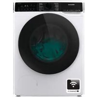
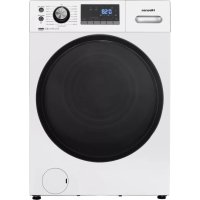
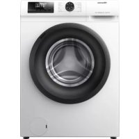
WFER1014VA - Washing machine HISENSE - Free user manual and instructions
Find the device manual for free WFER1014VA HISENSE in PDF.

User questions about WFER1014VA HISENSE
0 question about this device. Answer the ones you know or ask your own.
Ask a new question about this device
Download the instructions for your Washing machine in PDF format for free! Find your manual WFER1014VA - HISENSE and take your electronic device back in hand. On this page are published all the documents necessary for the use of your device. WFER1014VA by HISENSE.
USER MANUAL WFER1014VA HISENSE
NOISE, EXCESSIVE VIBRATIONS AND WATER LEAKAGES CAN BE CAUSED BY INCORRECT INSTALLATION.
NEVER MOVE THE APPLIANCE BY LIFTING IT BY THE WORKTOP.
- Read this "INSTALLATION GUIDE" before operating.
- Keep this "INSTALLATION GUIDE" for future reference.
- Read the general recommendations about disposing of packaging in the INSTRUCTION FOR USE.
PARTS SUPPLIED
• Package with small items
Instruction for use, installation guide, warranty card (depends on model)
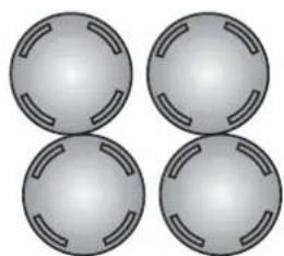
4 plastic caps
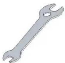
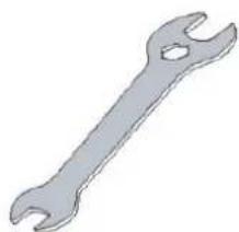
Wrench
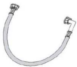
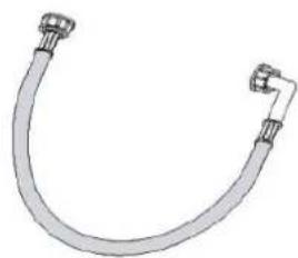
- Inlet hose (inside the machine or already installed) Cold inlet hose Hot inlet hose (if available, depending on models)
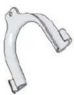
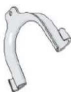
- "U"-bend (inside the machine or already installed)
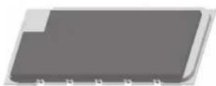
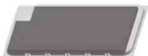
- Bottom cover(depends on model)
A
B
natural_image
Four identical gray spherical objects with internal slot patterns, arranged in a 2x2 grid (no text or symbols)©
natural_image
Simple illustration of a wrench (no text or symbols)D
natural_image
Pure diagram of a curved pipe or tube with two connectors, no text or symbols presentE
F
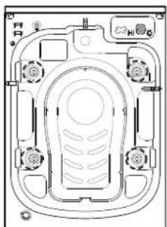
BEFORE USING THE WASHER, PLEASE REMOVE TRANSPORT BOLTS!
Important: Transport bolts which are not removed can cause damage to the appliance.
①
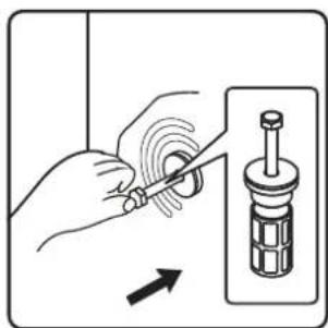
Screw off all transportation bolts for approx. 30mm with wrench following the direction of arrow shown (not fully screw it off).
natural_image
Top-down schematic of a mechanical or electrical component with no visible text, numbers, or symbols.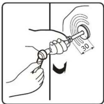
②
② Push two transportation bolts on horizontal direction inward and loose transportation bolt.
natural_image
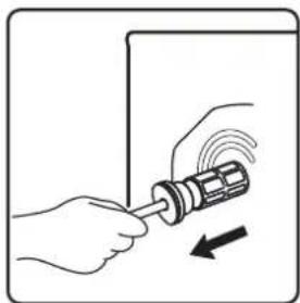
Illustration of a hand using a screwdriver to adjust a mechanical component (no text or symbols present)③
Pull out transportation bolt together with rubber part and plastic part.
natural_image
Illustration of hands using a screwdriver to adjust or install a component, with an arrow indicating motion (no text or symbols present)④
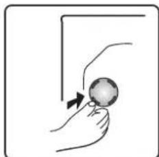
To ensure safety and reduce noise, you should install the transportation bolt cover supplied with the unit (see the annex accompanying the unit). Lean and place the transportation bolt into hole and press it following the shown direction until it clicks.
natural_image
Illustration of a hand holding a ball with an arrow indicating motion (no text or symbols)Important: Keep the transport bolts and the wrench for future transporting of the appliance and in this case refit the transport bolts in reverse order.
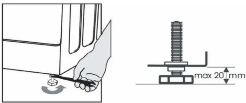
ADJUSTMENT OF THE FEET
The appliance must be installed on a solid and level floor surface (if necessary use a spirit level). If the appliance is to be installed on a wooden floor, distribute the weight by placing it on a 60x60cm sheet of plywood at least 3cm in thickness and secure it to the floor. If the floor is uneven, adjust the 4 leveling feet as required; do not insert pieces of wood etc. under the feet.
⑤
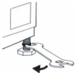
Slacken the locknut clockwise (see arrow) using the wrench.
natural_image
Diagram of a computer monitor with a wrench inserted, showing mechanical assembly (no text or symbols)⑥
Lift the machine slightly and adjust the height of the foot by revolving it.
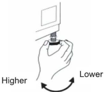
⑦
Important: tighten the locknut by turning it anti-clockwise towards the appliance casing.
INSTALL BOTTOM COVER
To realize quieter operation, a bottom cover is supplied with the unit (only applies to some of the Hisense washers). After installing the cover at the bottom of the washer, the noise level will be greatly reduced. Please ask for advice from specialists before installing the cover, nevertheless, the machine can be used without the bottom cover.

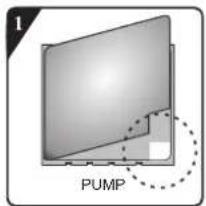
Noise-Reduction Bottom Plate Installation Instructions
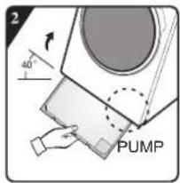
A: Stick acoustic wool to the side of bottom cover plate with the letter of "PUMP". Tilt the washer by 30^ - 40^ , when installing the bottom cover, please face the side with sound insulation upwards and attach 'PUMP' at the corner of the cover to the position of the pump in the washer.
B:
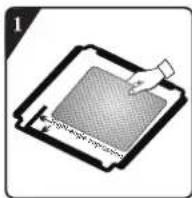
Before installing the noise-reduction bottom plate, align and paste the acoustic absorption wool with and along the right-angle impression on bottom plate (this procedure is unnecessary for some of the models without acoustic absorption wool).
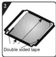
Remove surface paper on double sided tape at four sides of the bottom plate.
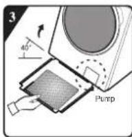
Incline the machine to an angle of 40^ and let the side with right-angle notch face towards front of the washing machine, as shown in the figure. Insert the side with oblique-angle notch between two foot screws at back of the washing machine completely in place. Then, install the bottom plate and ensure that it contacts with bottom of the washing machine closely.
natural_image
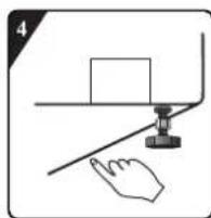
Simple line drawing of a hand pressing a block on a surface with a ruler (no text or symbols)Press the double sided tape on four sides manually to secure the noise-reduction palte to the machine body firmly.
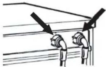
CONNECT THE WATER SUPPLY INLET HOSE

Hot (Depending on models)
Cold
If the water inlet hose is not already installed, it must be screwed to the appliance. The blue marked hose is only for cold water. Depending on the model, the hot waterhose marked with red should also be connected, for models having dual inlets.
natural_image
Pure diagram of two pipe connectors with arrows indicating direction, no text or symbols present
Screw by hand the inlet hose onto the tap, tightening the nut.
Attention:
• no kinks in the hose!
- The appliance must not be connected to the mixing tap of an un-pressurized water heater.
- Check water-tightness of connections by turning the tap completely on.
- If the hose is too short, replace it with a suitable length of pressure resistant hose (1000 kPa min, EN 50084 approved type).
- Check the inlet hose regularly for brittleness and cracks and replace if necessary.
• The washing machine can be connected without a non-return valve.
FILL INSTRUCTION
11
For Models with Dual Inlets
If you wish to connect hot and cold water supply (Fig.1):
- Fix the red marked inlet hose to the hot water tap and to the inlet valve with the red filter on the rear side of machine.
- Fix the other inlet hose to the cold water tap and to the inlet valve with the blue filter on the rear side of the machine.
Make sure:
a) The connections are tightly fixed
b) Do not invert their position (for example: cold fill into hot inlet valve and vice versa). If you wish to connect only the cold fill follow the below instructions (Fig. 2):
-
You need a Y-piece connector. This can be purchased from local hardware or plumbing supplier.
-
Fix the Y-piece connector to the cold fill tap.
-
Connect the two inlet valves present on the rear part of the machine to the Y-piece connector using the hoses provided.
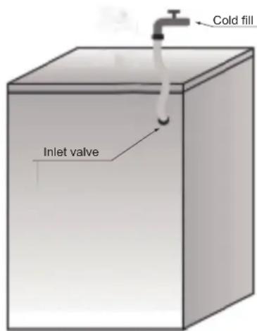
For Models with Single Inlet
Fix the inlet hose to the cold water tap and to the inlet valve on the rear side of the machine as Fig. 3
Ensure that:
All connections are tightly fixed.
Do not allow children to operate, crawl on, be near or inside your washer.
Note that during the wash cycles, the surface temperature of the porthole door may increase.
Close supervision of children is necessary when the appliance is used near children.
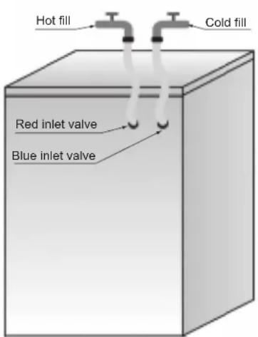
Fig.1 Fig.3
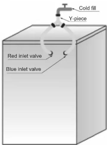
Fig.2
CONNECT THE DRAIN HOSE
12
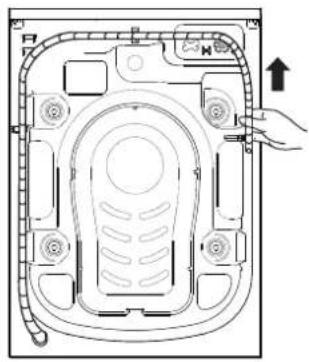
In case the drain hose is installed as shown below:
Unhook it only from the right clip (see arrow)
13
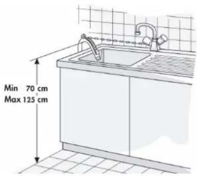
Connect the drain hose to the siphon or hook it over the edge of a sink by means of the "U" bend.
Fit the "U" bend E, if not already installed, at the end of the drain hose.
natural_image
Technical line drawing of a device interior with no visible text or symbols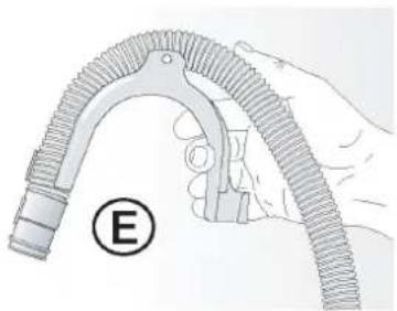
natural_image
Illustration of a hand holding a curved mechanical component with a circular label marked 'E' (no text or symbols on the diagram itself)Notes:
- Ensure that there are no kinks in the drain hose.
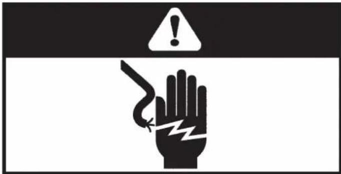
- Secure the hose so that it cannot fall down. After wash phase, machine will drain out hot water.
- Small hand basins are not suitable.
- To make an extension use a hose of the same type and secure the connections with clips.
• Max. Overall drain hose length: 2.50 m.
ELECTRICAL CONNECTION
Only use a socket with an earth connection.
Do not use extension leads or multi sockets.
Electrical supply must be adequate for the machine's 10A Current Rating.
The electrical power cable must be replaced exclusively by a licensed electrician.
Electrical connections must be made in accordance with local regulations.
Hisense

NOTICE D'INSTALLATION

BRUITS, VIBRATIONS EXCESSIVES ET FUITES D'EAU PEUVENT ÊTRE CAUSÉS PAR UNE MAUVAISE INSTALLATION.
NE DÉPLACEZ JAMAIS L'APPAREIL EN LE MANIPULANT PAR LE COUVERCLE.
natural_image
Four identical gray spherical objects with internal slot patterns, arranged in a 2x2 grid (no text or symbols)©
natural_image
Simple illustration of a wrench (no text or symbols)D
natural_image
Illustration of a U-shaped pipe fitting with two connectors (no text or symbols)E
F
AVANT D'UTILISER LE LAVE-LINGE, MERCI DE RETIRER LES BOULONS DE TRANSPORT !
natural_image
Technical line drawing of a mechanical component with no visible text or symbols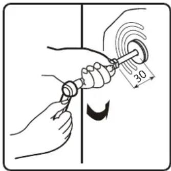

natural_image
Illustration of a hand using a screwdriver to adjust a mechanical component (no text or symbols present)
natural_image
Illustration of hands using a tool to adjust a component with motion arrows (no text or symbols)
natural_image
Illustration of a hand holding a ball with an arrow indicating motion (no text or symbols)natural_image
Diagram of a computer monitor with a wrench inserted, showing mechanical assembly (no text or symbols)
RACCORDEMENT DU FLEXIBLE D'ALIMENTATION EN EAU

RACCORDEMENT DU FLEXIBLE D'ÉVACUATION
12
natural_image
Technical line drawing of a mechanical device interior with no visible text or symbols13