HTS20 - Speaker stands Audizio - Free user manual and instructions
Find the device manual for free HTS20 Audizio in PDF.
| Product Type | Column Speaker Stand |
| Brand | Audizio |
| Model | HTS20 |
| Usage | Indoor only |
| Approximate Height | 80 cm |
| Base Diameter | 30 cm |
| Maximum Load Capacity | 25 kg |
| Stand Weight | 5 kg |
| Material | Steel |
| Color | Black |
| Package Contents | Stand, mounting screws, user manual |
| Installation | Recommended by a professional |
| Maintenance | Check every 3 months; clean with a dry cloth |
| Repairability | Not user repairable; replace entire unit if damaged |
| Safety | Do not exceed maximum load; small parts: choking hazard |
Frequently Asked Questions - HTS20 Audizio
User questions about HTS20 Audizio
0 question about this device. Answer the ones you know or ask your own.
Ask a new question about this device
Download the instructions for your Speaker stands in PDF format for free! Find your manual HTS20 - Audizio and take your electronic device back in hand. On this page are published all the documents necessary for the use of your device. HTS20 by Audizio.
USER MANUAL HTS20 Audizio
natural_image
Three black and white robotic arms with mounting flanges, shown from different angles (no text or symbols visible)INSTRUCTION MANUAL GEBRUIKSAANWIJZING BEDIENUNGSANLEITUNG MANUAL DE INSTRUCCIONES MANUEL D'INSTRUCTIONS INSTRUKCJA OBSŁUGI
V1.0
ENGLISH
Read the entire instruction manual before you start installation and assembly. If you have any questions regarding any of the instructions or warnings, please contact your local distributor for assistance.
CAUTION!
• Use with products heavier than the rated weights indicated may result in instability causing possible injury.
- Please closely follow the assembly instructions. Improper installation may result in damage or serious personal injury.
• Safety gear and proper tools must be used. This product should only be installed by professionals.
- Make sure that the supporting surface will safely support the combined weight of the equipment and all attached hardware and components.
• Use the mounting screws provided and DO NOT OVER TIGHTEN mounting screws.
• This product contains small items that could be a choking hazard if swallowed. Keep these items away from children.
- This product is intended for indoor use only. Using this product outdoors could lead to product failure and personal injury.
IMPORTANT! Ensure that you have received all parts according to the component checklist prior to installation. If any parts are missing or faulty, contact your place of purchase for a replacement.
MAINTENANCE Check that the product is secure and safe to use at regular intervals (at least every three months).
NEDERLANDS
natural_image
Technical line drawing of a cylindrical mechanical component with mounting base and side features (no text or symbols)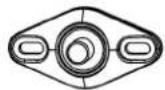
B
(×1)

C
1/4"-20×7/8" (×1)

D
M5×20 (×1)

ST4.2×19 (×1)

ST5.5×19 (×2)
K
ST5.5×45 (×2)

E
8#-32×5/8" (×1)

F
1/4"-20×1/2"
(x2)

G
M5×1/8"
(x1)

H
8#-32
(x1)

L
∅8×40 (×2)

M
M4×8 (×1)

N
4mm (x1)

O
D5 (x1)
STEP 1

natural_image
Technical line drawing of a mechanical device with a 7-degree angle and a compass needle (no text or symbols)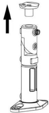
natural_image
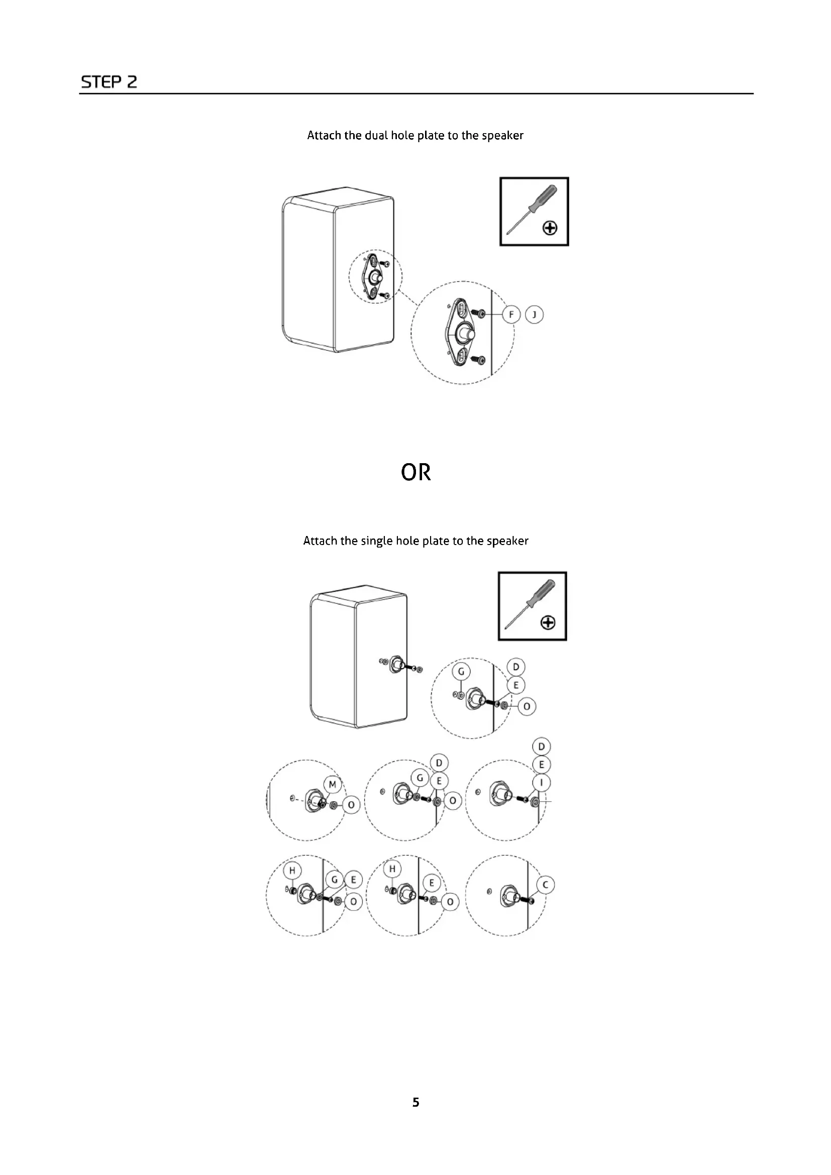
Technical line drawing of a mechanical device with an upward arrow indicator (no text or symbols present)Attach the dual hole plate to the speaker
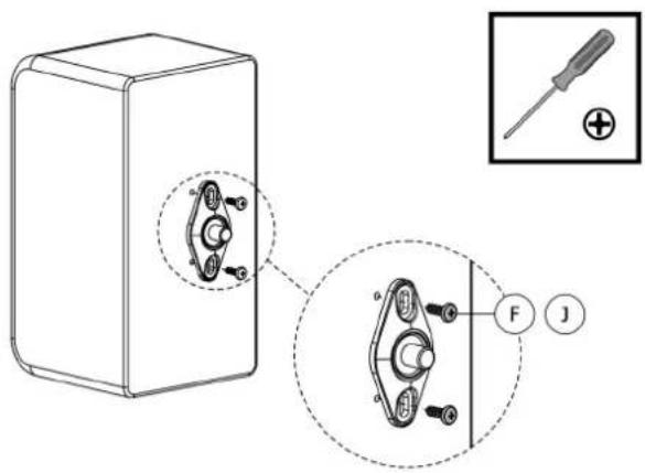
text_image
Technical diagram showing a mechanical assembly with labeled parts and a close-up of a screwdriver tool.OR
Attach the single hole plate to the speaker
text_image
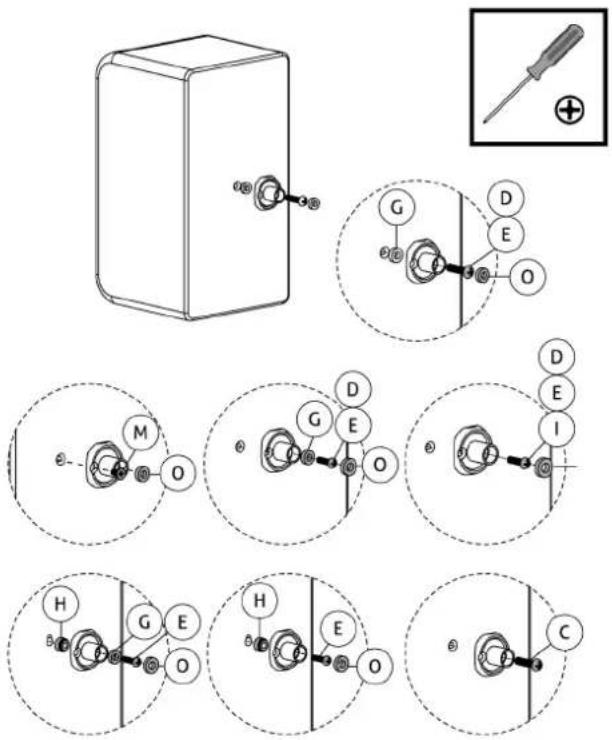
Technical diagram showing mechanical assembly with labeled components and exploded view of a toolInstall the speaker mount on a wooden stud
text_image
Technical diagram of a mechanical assembly with labeled components and a cross-sectional view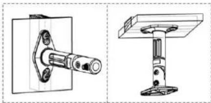
natural_image
Technical line drawings of two mechanical components: a flanged bracket and a support structure (no text or symbols)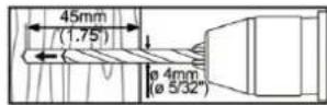
OR
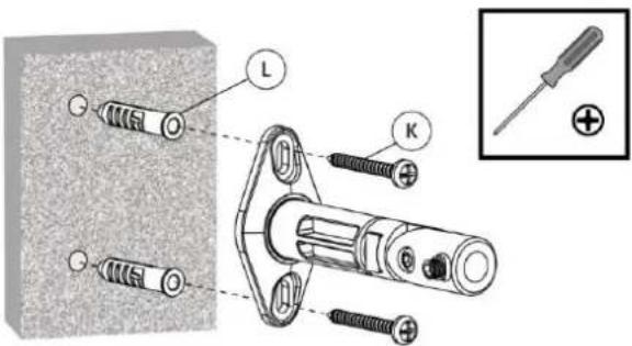
Install the speaker mount on a brick or concrete wall
text_image
Technical diagram showing exploded view of a mechanical assembly with labeled parts L, K, and a plus symbol for disassembled parts.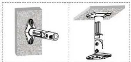
natural_image
Technical illustration of two mechanical components: a flanged bolt and a stepped bracket (no text or symbols)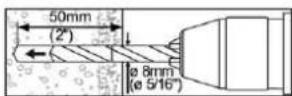
Attach the speaker mount to the double hole plate on the speaker
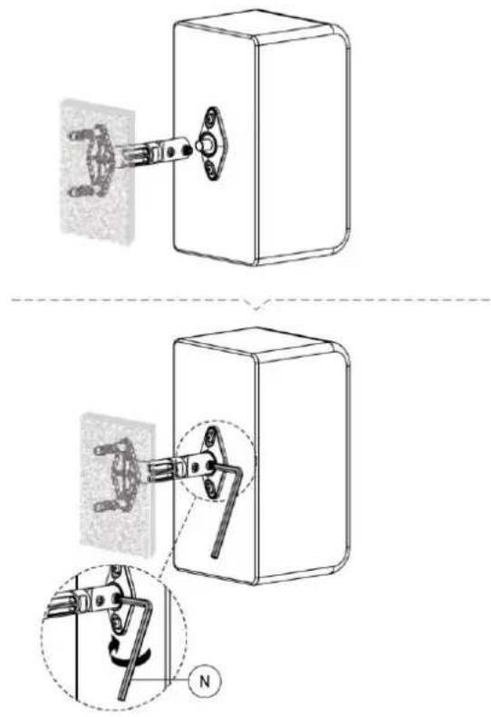
text_image
Technical diagram showing mechanical assembly steps with labeled components and a compass indicating rotation directionOR
Attach the speaker mount to the single hole plate on the speaker
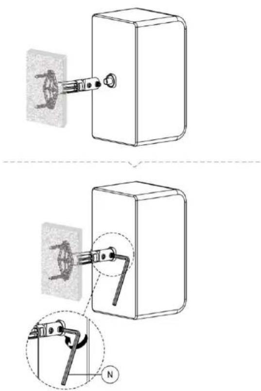
text_image
Technical diagram showing two mechanical assembly steps with labeled components and a magnified detail view.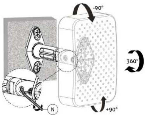
text_image
-90° 360° +90° NSpecifications and design are subject to change without prior notice.
www.tronios.com
Copyright © 2021 by Tronios The Netherlands