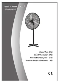
CFH212922.1 - Fan Emerio - Free user manual and instructions
Find the device manual for free CFH212922.1 Emerio in PDF.



| Product type | Pedestal fan |
| Brand | Emerio |
| Model | CFH212922.1 |
| Supply voltage | 220-240 V ~ 50 Hz |
| Power | 130 W |
| Air flow | 250 m³/min |
| Number of speeds | 6 (1 to 6) |
| Oscillation | Yes, 80° horizontal |
| Timer | 1 to 9 hours |
| Operating modes | Normal, sleep, ambiance (natural breeze) |
| Remote control | Yes, with CR2032 battery, range not specified |
| Digital display | Yes (speed and timer) |
| Adjustable height | Yes, via adjustment tube |
| Head tilt | Yes, adjustable |
| Protective grilles | Front and rear |
| Wall remote control base | Included |
| Frequency range (remote control) | 433.92 MHz |
| Maintenance | Damp cloth, do not immerse |
| Warranty | 2 years |
Frequently Asked Questions - CFH212922.1 Emerio
User questions about CFH212922.1 Emerio
0 question about this device. Answer the ones you know or ask your own.
Ask a new question about this device
Download the instructions for your Fan in PDF format for free! Find your manual CFH212922.1 - Emerio and take your electronic device back in hand. On this page are published all the documents necessary for the use of your device. CFH212922.1 by Emerio.
USER MANUAL CFH212922.1 Emerio
natural_image
Black outdoor fan with radial mesh structure on a stand (no text or symbols visible)Stand fan (EN)
Stand Ventilator (DE)
Instruction manual – English ...... - 2 -
Before use make sure to read all of the below instructions in order to avoid injury or damage, and to get the best results from the appliance. Make sure to keep this manual in a safe place. If you give or transfer this appliance to someone else make sure to also include this manual.
In case of damage caused by user failing to follow the instructions in this manual the warranty will be void. The manufacturer/importer accepts no liability for damages caused by failure to follow the manual, a negligent use or use not in accordance with the requirements of this manual.
-
This appliance can be used by children aged from 8 years and above and persons with reduced physical, sensory or mental capabilities or lack of experience and knowledge if they have been given supervision or instruction concerning use of the appliance in a safe way and understand the hazards involved.
-
Children shall not play with the appliance.
-
Cleaning and user maintenance shall not be made by children without supervision.
-
If the supply cord is damaged, it must be replaced by the manufacturer, its service agent or similarly qualified persons in order to avoid a hazard.
-
Before inserting the plug into the mains socket, please check that the voltage and frequency comply with the specifications on the rating label.
-
Disconnect the mains plug from the socket when the appliance is not in use and before cleaning.
-
Ensure that the mains cable is not hung over sharp edges and keep it away from hot objects and open flames.
-
Do not immerse the appliance or the mains plug in water or other liquids. There is danger to life due to electric shock!
-
To remove the plug from the plug socket, pull the plug. Do not pull the power cord.
-
Do not touch the appliance if it falls into water. Remove the plug from its socket, turn off the appliance and send it to an authorized service center for repair.
-
Do not plug or unplug the appliance from the electrical outlet with a wet hand.
-
Never attempt to open the housing of the appliance, or to repair the appliance yourself. This could cause electric shock.
-
Never leave the appliance unattended during use.
-
Do not use the appliance for other than intended use.
-
Keep the appliance away from damp, and protect from splashes.
-
Do not store or operate the appliance in the open air.
-
Keep the appliance in a dry place for storage, inaccessible to children (in its packaging).
-
Never put fingers or any other objects through the fan guards when the fan is running.
-
Never operate the product without the fan guards in place, as serious personal injury may result.
-
The appliance must be assembled completely before use.
-
Watch out for long hair! It can be caught in the fan owing to the air turbulence.
-
Do not point the air flow at people for a long time.
-
Ensure that the fan is switched off from the supply mains before removing the guard.
-
Do not use the fan in a wet room, such as a bathroom or laundry.
-
Do not use the fan in the presence of flammable substances or vapour such as alcohol, insecticides, petrol, etc.
-
Do not use the mains plug to start and stop the fan.
-
Do not pull the supply cord or place it near a heat source. Always unwind the cord completely to avoid overheating.
-
Do not attempt to move your fan whilst it is operating.
-
Always use the switch on the control panel to start and stop the fan.
-
Always keep a clearance of at least 200mm from walls, furniture and curtains.
-
Improper installation may result in the risk of fire, electric shock and/or injury to persons.
-
Keep blinds/curtains closed during the sunniest part of the day.
PARTS DESCRIPTION
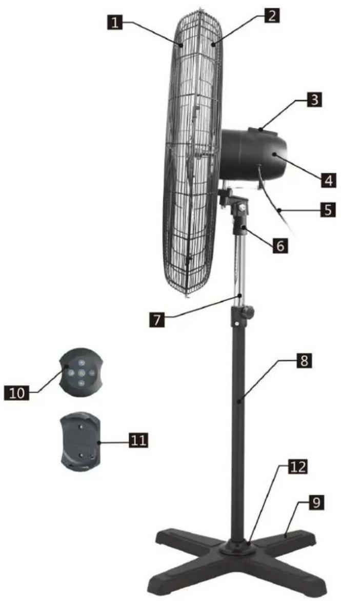
- Front grille
- Rear grille
- Control panel
- Motor unit
- Power cord
- Motor connector
- Height adjustment pipe
- Standing shaft
- Base
- Remote control
- Remote control base
- Decorative cap
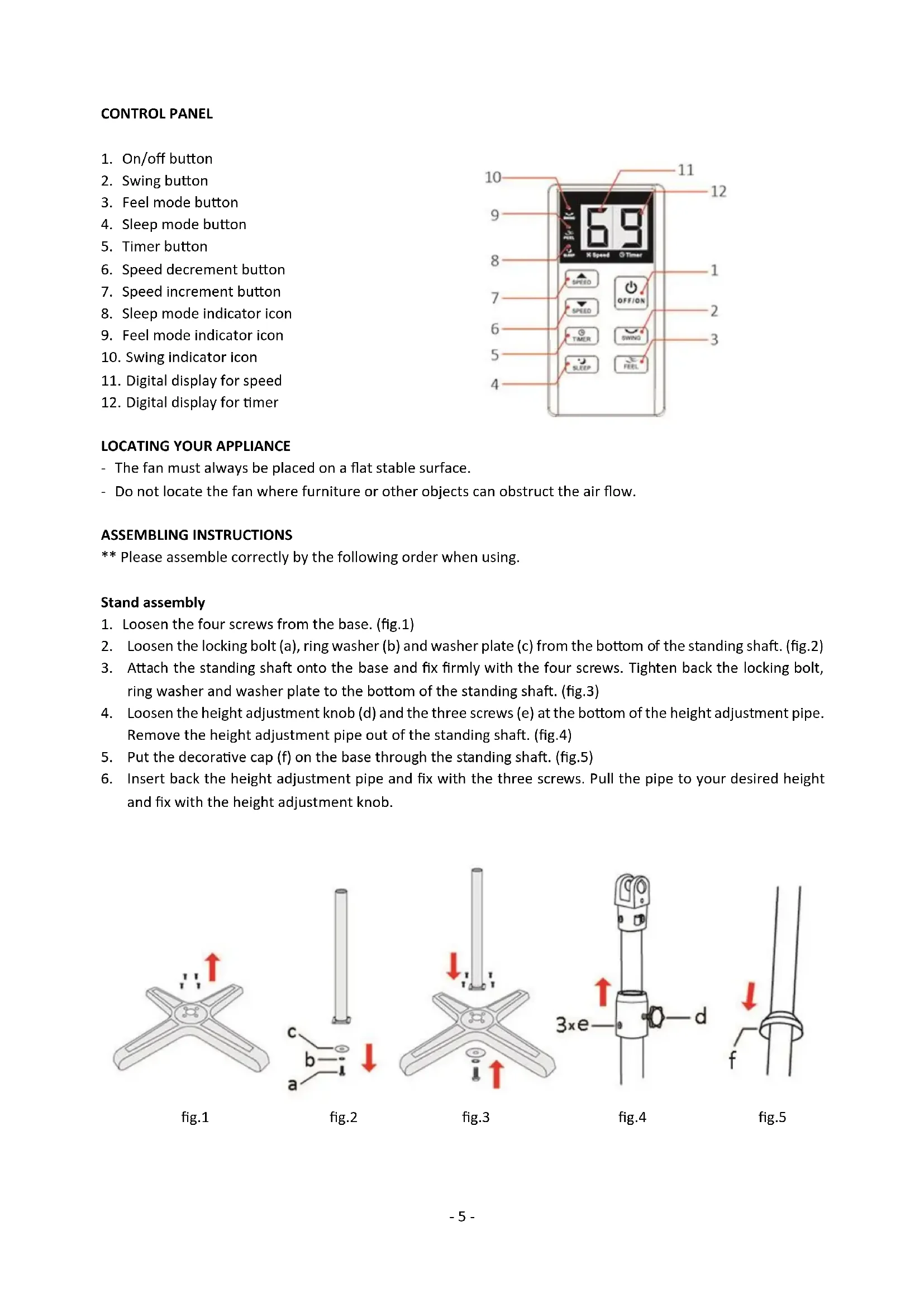
CONTROL PANEL
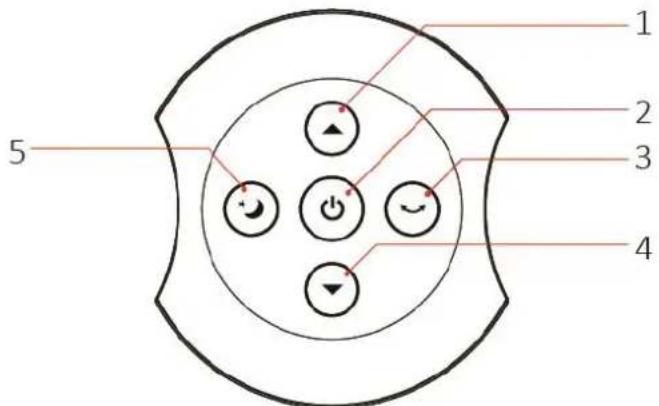
- On/off button
- Swing button
- Feel mode button
- Sleep mode button
- Timer button
- Speed decrement button
- Speed increment button
- Sleep mode indicator icon
- Feel mode indicator icon
- Swing indicator icon
- Digital display for speed
- Digital display for timer
LOCATING YOUR APPLIANCE
- The fan must always be placed on a flat stable surface.
- Do not locate the fan where furniture or other objects can obstruct the air flow.
ASSEMBLING INSTRUCTIONS
** Please assemble correctly by the following order when using.
Stand assembly
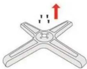
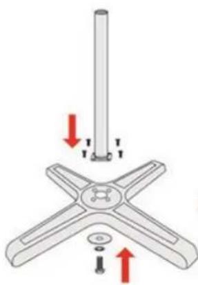
- Loosen the four screws from the base. (fig.1)
- Loosen the locking bolt (a), ring washer (b) and washer plate (c) from the bottom of the standing shaft. (fig.2)
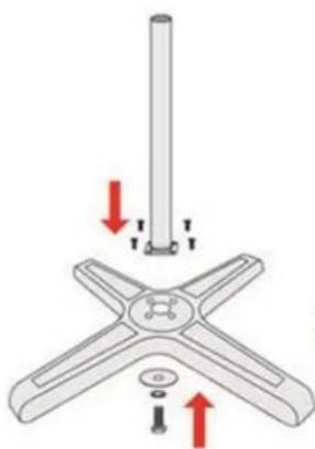
- Attach the standing shaft onto the base and fix firmly with the four screws. Tighten back the locking bolt, ring washer and washer plate to the bottom of the standing shaft. (fig.3)
- Loosen the height adjustment knob (d) and the three screws (e) at the bottom of the height adjustment pipe. Remove the height adjustment pipe out of the standing shaft. (fig.4)
- Put the decorative cap (f) on the base through the standing shaft. (fig.5)
- Insert back the height adjustment pipe and fix with the three screws. Pull the pipe to your desired height and fix with the height adjustment knob.
natural_image
Diagram of a four-blade fan with a central hub and upward arrow, no text or symbols presentfig.1
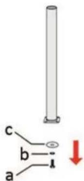
fig.2
natural_image
Mechanical assembly diagram showing a pin mounted on a star-shaped base with two arrows indicating force directions (no text or symbols present)fig.3
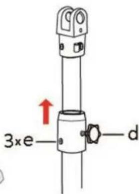
fig.4
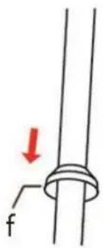
fig.5
Motor unit assembly
-
Loosen the stopper screw (g), tilt head adjustment bolt (h), washer (i) and fixing nut (j) from the motor connector. (fig. 6)
-
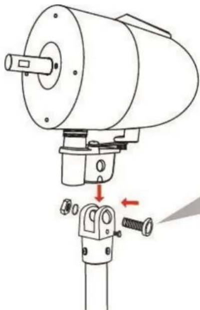
Slide the motor unit into the slot of the motor connector. Align the holes on the connector and the motor unit, insert the tilt head adjustment bolt, washer and fixing nut, and then use a wrench to fasten them firmly. Tighten back the stopper screw. (fig. 7)
-
Loosen the cable clamp screw (k) on the motor connector. Place the power cord (l) through the cable clamp (m). Then fix the screw back. (fig. 8)
Note: The length of the power cord between the motor unit and the cable clamp cannot be too short. Make sure there is enough space in between so that the fan head can operate smoothly for swing function.
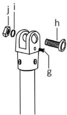
fig.6
natural_image
Technical diagram of a mechanical assembly with a cylindrical component and a base mount (no text or symbols)fig.7
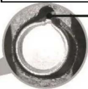
Make sure the top point of the bolt is correctly aligned with the groove in the hole.
natural_image
Close-up of a circular mechanical component with a central hole and textured outer ring (no visible text or symbols)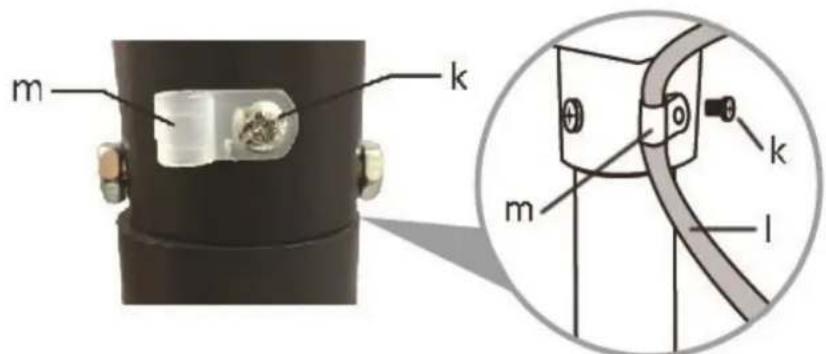
fig.8
Rear grille assembly
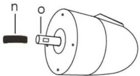
- Remove the black protective sleeve (n) from the motor shaft (o). (fig.9)
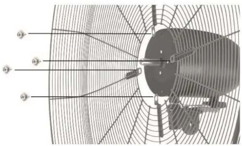
- Loosen the four screws (p) from the front side of the motor unit. (fig.10)
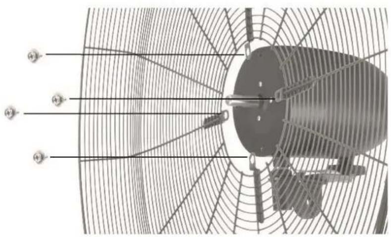
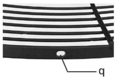
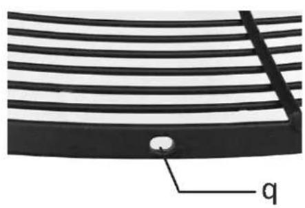
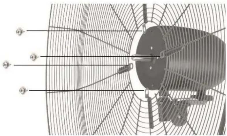
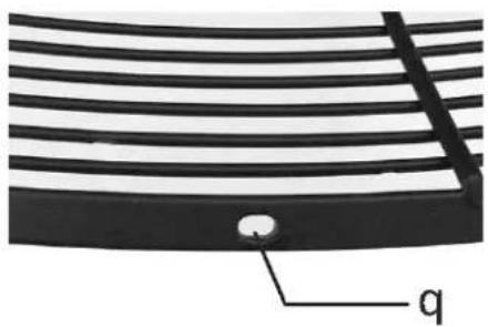
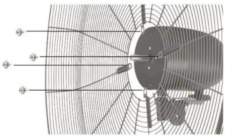
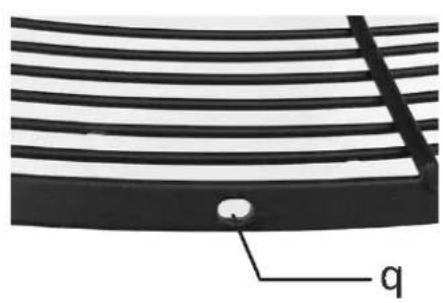
- Attach the rear grille onto the motor unit by aligning the screw holes on the grille and the front side of the motor unit. Tighten back the four screws. (fig.11) Make sure the screw hole (q) on the rear grille is at the bottom. (fig.12)
natural_image
Technical line drawing of a cylindrical mechanical component with labeled parts (no text or symbols present)fig.9
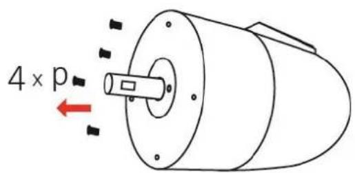
fig.10
natural_image
Technical diagram of a fan or turbine blade assembly with radial blades and central hub (no text or symbols)fig.11
natural_image
Close-up of a curved black panel with parallel lines and a small circular feature labeled 'q' (no text or symbols beyond label)fig.12
Fan blade assembly
- Loosen the screw (r) from the fan blade (s). (fig.13)
- Insert the center of the fan blade (align with the groove/flat part (t) of the motor shaft) into the motor shaft and tighten the screw on the middle of the fan blade. (fig.14)
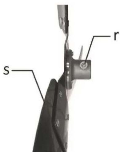
fig.13
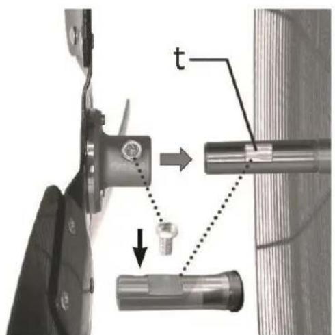
fig.14
Front grille assembly
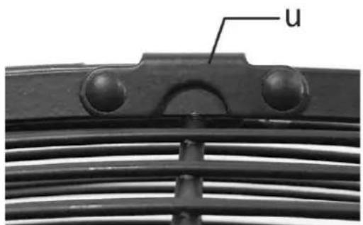
- Put the hook (u) of the front grille on the top of the rear grille. (fig.15)
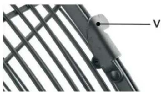
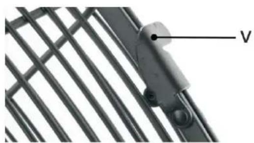
- Attach the front grille to the rear grille and then close the guard clips (v). (fig.16)
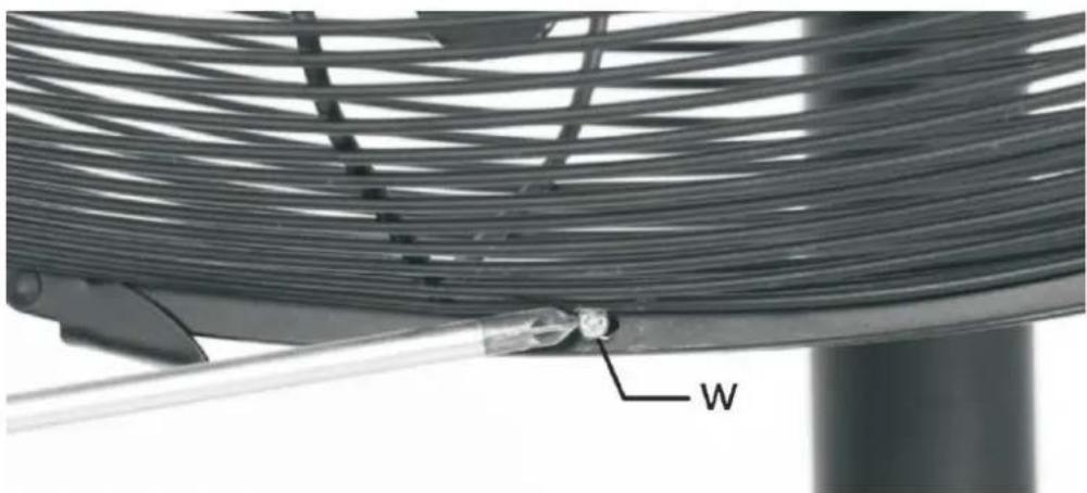
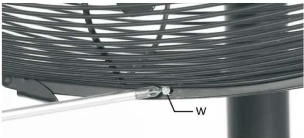
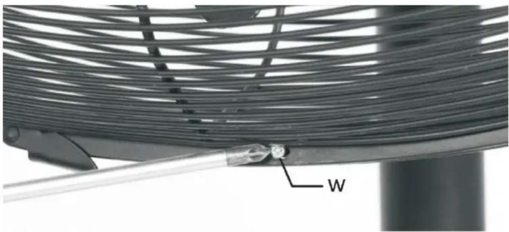
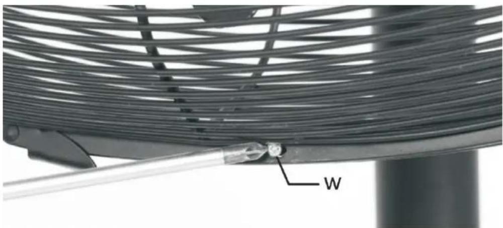
- Secure the front and rear grilles by fastening the fixing screw with nut (w). (fig.17)
natural_image
Close-up of a mechanical component with threaded metal and labeled component 'u' (no other text or symbols visible)fig.15
natural_image
Close-up of a metal grate with a labeled component 'V' (no other text or symbols visible)fig.16
natural_image
Close-up of a coiled wire or cable structure with a labeled component 'W' (no other text or symbols visible)fig.17
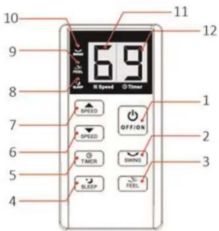
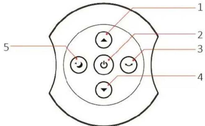
REMOTE CONTROL
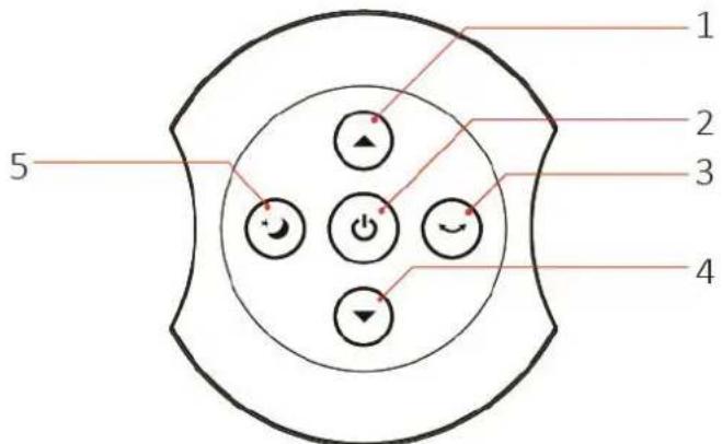
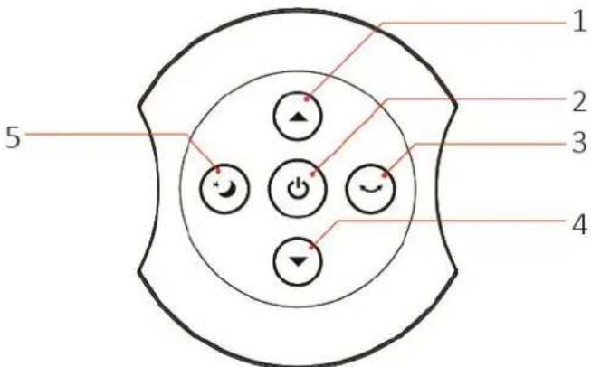
- Speed increment button
- On/off button
- Swing button
- Speed decrement button
- Sleep mode button
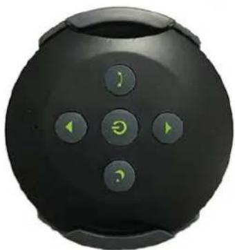
This unit has a remote control. One piece of CR2032 battery is to be installed. The functions of the remote control buttons are the same as of the buttons on the control panel. Remember to remove the plastic isolation piece inside the battery cover when you use it for the first time.
Remote control pairing
Important: By default, the remote control in the box is paired already with the fan with which is it supplied. However, if you lost the remote control and purchase a new one, then please pair the remote control with the fan before use.
Steps to pair:
- Ensure that the battery is placed inside the remote control.
- Plug in the appliance.
-
Once the beep sound is heard the remote control is paired with the fan.
-
Press the on/off button on the remote control 4 times and hold it in the position till the beep sound is heard on the 4^th time.
Base mounting of the remote control
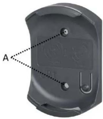
- Drill two holes on the wall according to the holes (A) on the remote control base.
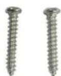
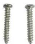
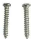
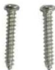
- Insert the two plastic anchors (B) in the holes on the wall, attach the remote control base onto the plastic anchors, and then insert the two screws (C) through the holes to fix the base.
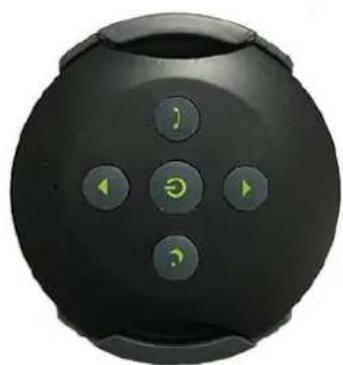
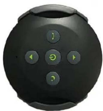
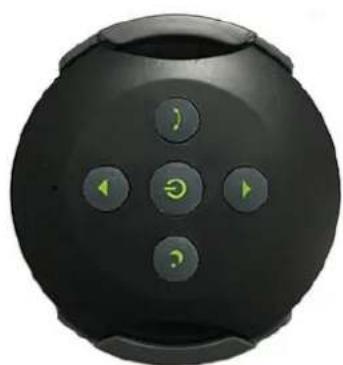
- Press the remote control into the base. Rotate the remote control by 90 degrees to have it fixed in place.
natural_image
Close-up of a gray electronic device casing with labeled point A and internal components (no text or symbols beyond label)
B
C
natural_image
Black spherical device with five control buttons (no text or symbols visible)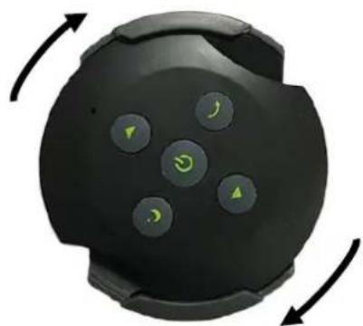
natural_image
Close-up of a black circular device with five green control buttons and directional arrows indicating rotation (no text or symbols)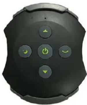
natural_image
Close-up of a black remote control device with five function buttons (power, smile) and navigation arrows (no text or symbols visible)OPERATING INSTRUCTIONS
Please press the buttons on the control panel or the buttons on the remote control to choose your desired functions. Plug in the appliance.
- On/off button:
Press the on/off button to turn on the unit. The unit starts to work at speed 3. Press the button again, the unit will be turned off.
- Speed button:
Press the speed button “”/“” to set your desired wind speed 1 / 2 / 3 / 4 / 5 / 6, indicated on the digital display.
- Timer button:
Press the timer button to set your desired working time (1-9h). Once the timer is set, the corresponding time value will start to blink on the digital display. The unit will be turned off automatically when the pre-set time is reached. To cancel the timer, press and hold the timer button on the control panel until the time value on the digital display disappear.
Note: This function can only be used by using the control panel. Remote control has no timer button.
- Swing button:
Press the swing button to turn on the oscillation function. The fan head will oscillate horizontally at an angle of 80 degree from left to right. Press the button again to turn off the function.
- Sleep mode button:
Press the button to enter the sleep mode. The fan will be set to run at a quieter and lower speed setting.
The wind speed is in default and not to be adjusted manually. If you adjust the wind speed manually, the fan will exit the sleep mode.
- Feel mode:
Press the button to enter the feel mode. The fan will vary the wind speed randomly, giving the effect of natural breeze. The wind speed is in default and not to be adjusted manually. If you adjust the wind speed manually, the fan will exit the feel mode.
Note: This function can only be used by using the control panel. Remote control has no feel button.
NOTE: The appliance will keep working with the previous wind speed and swing function once turned on again without being unplugged. If the appliance has been disconnected before, it will begin to work at speed 3 once turned on again.
CLEANING AND MAINTENANCE
-
Before servicing the fan and after each occasion of use, switch off the appliance and unplug the mains cable from the socket.
-
Never immerse the appliance in water (danger of short-circuit). To clean the appliance, only wipe it down with a damp cloth and dry it carefully. Always take out the mains plug first.
-
Take care that excessive dust does not build up in the air-intake and air-outlet grille, and clean it occasionally using a dry brush or vacuum cleaner.
-
Avoid the use of gasoline, benzene, thinner, etc. as they may result in damage to the appliance.
-
Store the appliance in a clean dry place when not in use.
TECHNICAL DATA
Operating voltage: 220-240V \~ 50Hz
Power consumption: 130W
Air flow: 250m^3/min
Frequency Range: 433.92MHz, Single Channel
Declaration of Conformity
We, Emerio, declare under our sole responsibility that the product: CFH-212922.1 is in conformity with the essential requirements and other relevant requirements of the RED Directive (2014/53/EU)
The complete CE declaration is available at the following address: www.emerio.eu
GUARANTEE AND CUSTOMER SERVICE
Before delivery our devices are subjected to rigorous quality control. If, despite all care, damage has occurred during production or transportation, please return the device to your dealer. In addition to statutory legal rights, the purchaser has an option to claim under the terms of the following guarantee:
For the purchased device we provide 2 years guarantee, commencing from the day of sale. If you have a defective product, you can directly go back to the point of purchase.
Defects which arise due to improper handling of the device and malfunctions due to interventions and repairs by third parties or the fitting of non-original parts are not covered by this guarantee. Always keep your receipt, without the receipt you can't claim any form of warranty. Damage caused by not following the instruction manual, will lead to a void of warranty, if this results in consequential damages then we will not be liable. Neither can we hold responsible for material damage or personal injury caused by improper use if the instruction manual is not properly executed. Damage to accessories does not mean free replacement of the whole appliance. In such case please contact our service department. Broken glass or breakage of plastic parts is always subject to a charge.
Defects to consumables or parts subjected to wearing, as well as cleaning, maintenance, replacement of said parts or shipping and transportation costs to and from any place of repair are not covered by the warranty and are to be paid.
ENVIRONMENT FRIENDLY DISPOSAL
Recycling – European Directive 2012/19/EU
This marking indicates that this product should not be disposed with other household wastes. To prevent possible harm to the environment or human health from uncontrolled waste disposal, recycle it responsibly to promote the sustainable reuse of material resources. To return your used device,
please use the return and collection systems or contact the retailer where the product was purchased. They can take this product for environmentally safe recycling.

BATTERY MUST BE RECYCLED OR DISPOSED OF PROPERLY. DO NOT OPEN. DO NOT DISPOSE
OR IN FIRE OR SHORT CIRCUIT.
EMERIO Switzerland AG
Industriestrasse 47
6300 Zug
Switzerland
SICHERHEITSHINWEISE
natural_image
Technical diagram of a mechanical assembly with a cylindrical component and a base mount (no text or symbols)Abb. 7
natural_image
Close-up of a circular mechanical component with a central hole and textured outer ring (no visible text or symbols)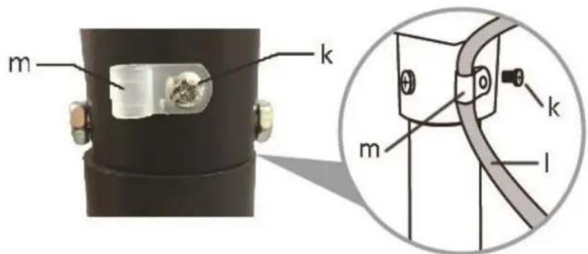
Abb. 8
Hinteres Ventilatorgitter montieren
natural_image
Technical line drawing of a cylindrical mechanical component with labeled parts (no text or symbols present)Abb. 9
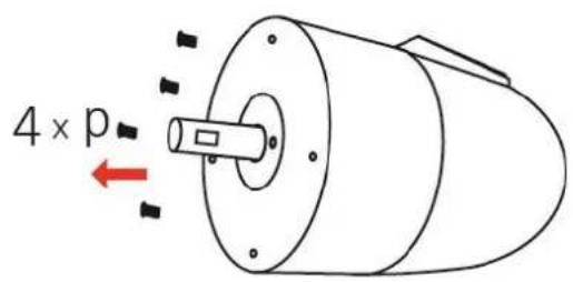
Abb. 10
natural_image
Technical diagram of a fan or blade assembly with radial mesh structure and labeled components (no text or symbols present)Abb. 11
natural_image
Diagram of a curved black structure with parallel lines and a labeled point 'q' (no text or symbols beyond label)Abb. 12
natural_image
Close-up of a metal grate with a labeled component 'V' (no other text or symbols visible)Abb. 16
natural_image
Close-up of a coiled wire or cable structure with a labeled component 'W' (no other text or symbols visible)Abb. 17
FERNBEDIENUNG
natural_image
3D model of a device casing with labeled point A and internal components (no text or symbols beyond label)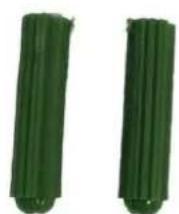
B
C
natural_image
Black spherical device with five control buttons and a green circular icon on the front (no text or symbols visible)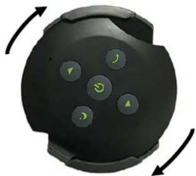
natural_image
Close-up of a black circular device with five green control buttons and directional arrows indicating rotation (no text or symbols)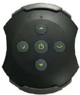
natural_image
Close-up of a black remote control device with five function buttons (no text or symbols visible)BEDIENUNG
EMERIO Switzerland AG
Industriestrasse 47
6300 Zug
Switzerland
CONSIGNES DE SÉCURITÉ
natural_image
Diagram of a four-bladed mechanical component with an upward arrow indicating motion or force (no text or symbols)Schéma 1
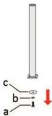
Schéma 2
natural_image
Diagram of a four-blade fan with a vertical rod and red arrows indicating force or adjustment (no text or symbols)Schéma 3
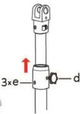
Schéma 4
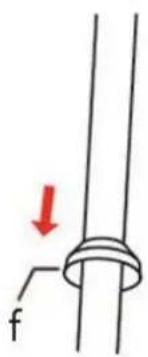
Schéma 5
natural_image
Diagram of a cylindrical mechanical component with labeled parts (no text or symbols present)Schéma 9
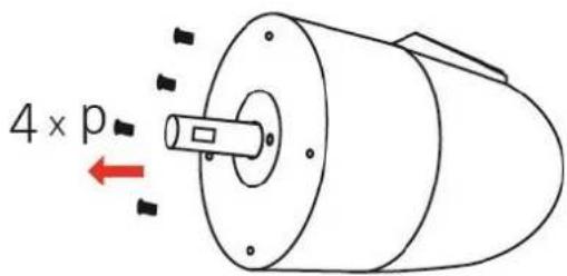
Schéma 10
natural_image
Technical diagram of a fan or impeller with radial blades and central hub (no text or symbols)Schéma 11
natural_image
Diagram of parallel lines with a labeled point 'q' at the bottom (no other text or symbols)Schéma 12
natural_image
Close-up of a mechanical component with threaded metal and labeled component 'u' (no other text or symbols visible)Schéma 15
natural_image
Close-up of a metal bracket with a labeled component 'V' on its side (no other text or symbols visible)Schéma 16
natural_image
Close-up of a coiled wire or cable structure with a labeled component 'W' (no other text or symbols visible)Schéma 17
TÉLÉCOMMANDE
natural_image
3D model of a gray plastic electronic device casing with labeled points A and B (no text or symbols on the object itself)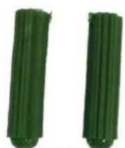
B
natural_image
Black spherical device with five control buttons (no text or symbols visible)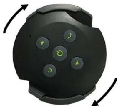
natural_image
Close-up of a black smartwatch with five green control buttons and directional arrows indicating rotation (no text or symbols)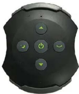
natural_image
Close-up of a black smart home control panel with five function buttons (no text or symbols visible)INSTRUCTIONS DE FONCTIONNEMENT
EMERIO Switzerland AG
Industriestrasse 47
6300 Zug
Switzerland
natural_image
Technical line drawing of a cylindrical mechanical component with labeled parts (no text or symbols present)Fig. 9
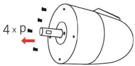
Fig. 10
natural_image
Technical diagram of a fan or blade assembly with radial mesh structure and labeled components (no text or symbols present)Fig. 11
natural_image
Diagram of a curved black structure with parallel lines and a labeled point 'q' (no text or symbols beyond label)Fig. 12
natural_image
Close-up of a metal bracket with a labeled component 'V' (no other text or symbols visible)Fig. 16
natural_image
Close-up of a coiled wire or cable structure with a labeled component 'W' (no other text or symbols visible)Fig. 17
TELECOMANDO
natural_image
Close-up of a dark gray electronic device casing with labeled point A and internal components (no readable text or symbols)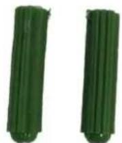
B
C
natural_image
Black circular device with five control buttons and green play icons (no text or symbols visible)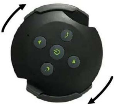
natural_image
Circular device with five green control buttons and directional arrows, no visible text or symbols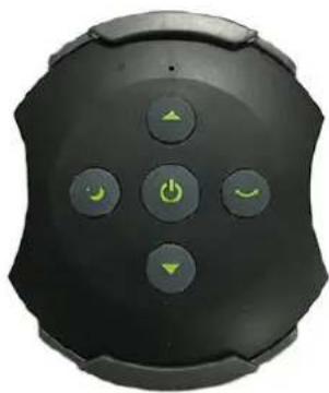
natural_image
Close-up of a black remote control device with five function buttons (no text or symbols visible)UTILIZZO
EMERIO Switzerland AG
Industriestrasse 47
6300 Zug
Switzerland

- CONTROL PANEL
- LOCATING YOUR APPLIANCE
- ASSEMBLING INSTRUCTIONS
- Stand assembly
- Motor unit assembly
- Rear grille assembly
- Fan blade assembly
- Front grille assembly
- Remote control pairing
- Steps to pair:
- Base mounting of the remote control
- OPERATING INSTRUCTIONS
- CLEANING AND MAINTENANCE
- TECHNICAL DATA
- GUARANTEE AND CUSTOMER SERVICE
- ENVIRONMENT FRIENDLY DISPOSAL
- SICHERHEITSHINWEISE
- Hinteres Ventilatorgitter montieren
- BEDIENUNG
- CONSIGNES DE SÉCURITÉ
- INSTRUCTIONS DE FONCTIONNEMENT
- UTILIZZO
Brand : Emerio
Model : CFH212922.1
Category : Fan