
F1500UPS - Uninterruptible power supply Furman - Free user manual and instructions
Find the device manual for free F1500UPS Furman in PDF.

| Product Type | Uninterruptible Power Supply (UPS) |
| Brand | Furman |
| Model | F1500UPS |
| Dimensions (H x W x D) | 3.5 inches x 19.2 inches x 17 inches |
| Weight | 72 lbs (approx. 32.7 kg) |
| Input AC Voltage | 90 - 140 VAC |
| Input Frequency | 57 - 63 Hz |
| Surge Protection | SMP (Series Multi-Stage Protection) – non-sacrificial, clamped at 188 Vpk |
| Noise Filtering | LiFT (Linear Filtering Technology) – linear filtering without ground contamination |
| Extreme Voltage Shutdown | EVS (Extreme Voltage Shutdown) – cuts power in case of prolonged overvoltage |
| Automatic Voltage Regulation (AVR) | Sensitive mode (98-135 VAC → 120 V ±5%) or standard mode (93-145 VAC → 120 V ±10%) |
| UPS Output Waveform | Pure sine wave (120 V ±5 V, 60 Hz ±1%) |
| UPS Power | 1500 VA / 900 W (power factor 0.6) |
| Full Load Runtime | 12 minutes (900 W) |
| Half Load Runtime | 32 minutes (450 W) |
| Transfer Time | < 4 ms |
| Maintenance and Cleaning | Use a dry cloth; do not open the case; battery replacement by qualified professional only |
| Safety | Do not use with medical or life-support equipment; do not plug in high-consumption devices; protect from moisture |
| Spare Parts and Repairability | Replaceable battery (ref. BC-1500); optional external battery kit BAT1500-EXT; optional BlueBOLT-CV1 interface card |
| General Information | Limited 3-year warranty (2 years for battery); technical support: 877-486-4738 |
Frequently Asked Questions - F1500UPS Furman
User questions about F1500UPS Furman
0 question about this device. Answer the ones you know or ask your own.
Ask a new question about this device
Download the instructions for your Uninterruptible power supply in PDF format for free! Find your manual F1500UPS - Furman and take your electronic device back in hand. On this page are published all the documents necessary for the use of your device. F1500UPS by Furman.
USER MANUAL F1500UPS Furman
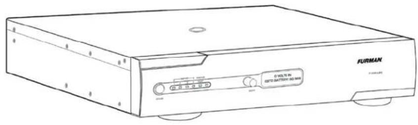
F1500-UPS UNINTERRUPTIBLE POWER SUPPLY
Alimentation d'énergie non interruptible programmable / Fuente de alimentación continuo programable


F1500-UPS UNINTERRUPTIBLE POWER SUPPLY OWNER'S MANUAL
F1500-UPS GUIDE DE L'UTILISATEUR / F1500-UPS MANUAL DEL PROPIETARIO
FURMAN®

F1500-UPS OWNER'S MANUAL

F1500-UPS GUIDE DE L'UTILISATEUR

F1500-UPS MANUAL DEL PROPIETARIO
FURMAN'S F1500-UPS FEATURES
- SMP (Series Multi-Stage Protection) Non Sacrificial Surge Protection
- LiFT (Linear Filtering Technology) Noise Filtration
• EVS (Extreme Voltage Shutdown) Voltage Protection - True sine wave output
• Dual Learning IR Output Controls - BlueBOLT™ Compatible (with BlueBOLT-CV1 interface card, sold separately) or Fully Programmable RS-232 with Open Source Protocol (Included)
- USB Interface
• (2) Programmable Critical Load Management AC Outlet Banks and (2) Non-critical Load AC Outlet Banks - Optional Battery Extension Pack available for extended runtime capability
- Optional rear panel mounted TCP/IP addressability module for remote control via internet
INTRODUCTION
Thank you for purchasing a Furman F1500-UPS Uninterruptible Power Supply, and congratulations on your choice. The F1500UPS Uninterruptible Power Supply features Furman's revolutionary Series Multi-Stage Protection (SMP) circuit, Extreme Voltage Shutdown (EVS), and our exclusive Linear Filtering Technology (LiFT). Together, these technologies comprise precisely what our customers have come to expect from Furman - uncompromised AC protection and purification. Our F1500-UPS has been precisely engineered to exceed the critical demands of audio/video professionals, contractors, broadcasters, and musicians alike.
SMP (SERIES MULTI-STAGE PROTECTION)
Furman's SMP surge suppression virtually eliminates service calls and costly "down time". Traditional surge suppression circuits sacrifice themselves when exposed to multiple transient voltage spikes, requiring the dismantling of your system and repair of your surge suppressor. Not so with Furman's SMP. Damaging transient voltages are safely absorbed, clamped, and dissipated. Your connected equipment is protected, while your Furman protects itself!
Unique to Furman's SMP is its unparalleled clamping voltage, defined as the amount of voltage that is allowed to pass through to your equipment when the protection device is subjected to a transient surge or spike. While other designs offer clamping voltages that are well above 330 Vpk, Furman's SMP clamps at 188 Vpk, (133 VAC RMS) even when tested with multiple 6000 Vpk - 3000 amp surges! This unprecedented level of protection is only available with Furman's SMP technology.
EVS (EXTREME VOLTAGE SHUTDOWN)
Furman's trusted over/under-voltage (EVS) circuitry protects against prolonged overvoltage conditions, such as accidental connections to 208 or 240 VAC, or an intermittent neutral. It does so by monitoring the incoming voltage and, when an unsafe condition is detected, triggering a relay which shuts off the incoming power until the over/under-voltage condition is corrected.
LIFT (LINEAR FILTERING TECHNOLOGY)
Unfortunately, traditional AC power conditioners have been designed for unrealistic laboratory conditions. Prior technologies, whether multiple-pole or conventional series-mode filters, could actually harm audio and video performance more than they help, due to the resonant peaking of their antiquated, non-linear designs. Under certain conditions, these designs can actually add more than 10 dB of noise to the incoming AC line! Worse still, lost digital data, the need to reboot digital presets, or destruction of sensitive digital converters are frequently caused by excessive voltage spikes and AC noise contaminating the equipment ground. Furman's LiFT takes a different approach, ensuring optimal performance through linear AC noise filtering with no ground contamination.
SAFETY INFORMATION
Before you begin unpacking your unit, Inspect the F1500-UPS upon receipt. In addition to this manual the box should contain the following:
- F1500-UPS Unit with Captive Power Cord
- DB 9 Serial Cable
- Rack Mounting Kit
- Power Control Software CD
- USB Cord
IMPORTANT SAFETY INSTRUCTIONS
(Please read prior to installation)
This manual contains important instructions that should be followed during installation and maintenance of the F1500-UPS and batteries.
Please read and follow all instructions carefully during installation and operation of the unit. Read this manual thoroughly before attempting to unpack, install, or operate.
CAUTION! The F1500-UPS must be connected to an AC power outlet with fuse or circuit breaker protection.
DO NOT plug the machine into an outlet that is not grounded, or without GFCI protection if it is plugged into an isolation transformer. If you need to de-energize this equipment, turn off and unplug the F1500-UPS.
CAUTION! DO NOT USE FOR MEDICAL OR LIFE SUPPORT EQUIPMENT! Furman does not sell products for life support or medical applications. DO NOT use in any circumstance that would affect operation or safety of any life support equipment, with any medical applications, or patient care.
CAUTION! The battery can energize hazardous live parts inside even when the AC input power is disconnected.
CAUTION! To prevent the risk of fire or electric shock install in a temperature and humidity controlled indoor area, free of conductive contaminants. [Please see specifications for acceptable temperature and humidity range].
CAUTION! To reduce the risk of electric shock, do not remove the cover. No user serviceable parts inside. (only qualified service professionals should replace the battery pack).
CAUTION! To avoid electrical shock, turn off the unit and unplug it from the AC power source before installing a component.
CAUTION! DO NOT USE WITH OR NEAR AQUARIUMS! To reduce the risk of fire, do not use with or near aquariums. Condensation from the aquarium can come in contact with metal current contacts and cause the machine to short out.
NOTE: AC Power management devices, such as a UPS, have certain limitations with regard to reactive loads and wattage. The F1500-UPS has a handling capacity of 1500VA or approximately 7.5 amps. Excessive power consumption beyond these specifications can affect battery life and performance.
INSTALLATION
Recharging the battery of your F1500-UPS for at least six to eight hours is highly recommended to insure that the battery's maximum charge capacity is achieved prior to initial use. Charge loss may occur during shipping and storage. To recharge the battery, simply leave the unit plugged into an AC outlet. The unit will charge in both the ON as well as the OFF position. If you wish to use the software, connect the enclosed USB cable to the USB port on the F1500-UPS and an open USB port on the computer or server.
DO NOT plug a space heater, vacuum cleaner, paper shredder or other large electrical device into the F1500-UPS. The power demands of these devices will overload and possibly damage the unit.
Plug the F1500-UPS into a 2 pole, 3 wire grounded receptacle. Make sure the wall branch outlet is protected by a fuse or circuit breaker and does not service equipment with large electrical demands (e.g. refrigerator, copier, etc.) Avoid using extension cords. If used, the extension cord must be UL or CSA Listed, minimum 14 AWG, 3-wire grounded, and rated for 15 Amps.
The F1500-UPS will automatically charge the battery whenever it is plugged into an AC outlet. To maintain optimal battery charge, leave the F1500-UPS plugged into an AC outlet at all times.
NOTE: To store your F1500-UPS for an extended period, cover it and store with the battery fully charged. Recharge the battery every three months to ensure battery life.
COMMUNICATION INTERFACE
BlueBOLT™ Compatible [with BlueBOLT-CV1 interface card, sold separately]: provides remote access to reboot components, power equipment on or off, and monitor power quality from anywhere in the world. Contact Furman for price and availability.
The RS-232 communication card provided with the F1500-UPS allows connection and communication between the F1500-UPS and an automation, media server, or computer system. This allows the installer to program a number of variables including the Critical Load Battery Threshold. See the software documentation for more information.
EXTERNAL BATTERY CONNECTORS
Furman's BAT1500-EXT external battery pack (sold separately) offers extended battery runtime when used in conjunction with the Furman F1500-UPS. Contact Furman for price and availability.
F1500-UPS FRONT PANEL INSTALLATION
The F1500-UPS is shipped with the front panel unattached to ensure that no damage is caused during shipping. Before the F1500-UPS can be used, the front panel must be installed.
1. Remove front panel from shipping inserts.
2. Verify that the battery connectors are connected, red-to-red, black-to-black.
If not connected, perform steps 2 and 6 in the BATTERY REPLACEMENT section.
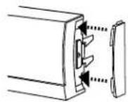
3. [Optional] Install the supplied rubber end-caps to the sides of the front panel. Push the curved edge of the end-cap into the mating slots of the front panel.
4. Carefully align the front panel connector and latches with the F1500-UPS.
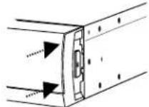
5. Gradually apply pressure to the left and right ends of the front panel until you hear the latches 'click'.
IMPORTANT SAFETY INSTRUCTIONS FOR BATTERY REPLACEMENT
(Please read prior to battery replacement installation)
CAUTION! RISK OF EXPLOSION IF BATTERY IS REPLACED BY AN INCORRECT TYPE.
CAUTION! When replacing batteries, replace with the same type of the original batteries.
CAUTION! Before replacing batteries, remove conductive jewelry such as chains, wrist watches, and rings. High energy through conductive materials could cause severe burns.
CAUTION! Do not dispose of batteries in a fire. The batteries may explode.
CAUTION! Do not open or mutilate batteries. Released material is harmful to the skin and eyes. It may be toxic.
CAUTION! Do not attempt to replace batteries. Please refer battery replacement to a qualified service technician only!
F1500-UPS BATTERY REPLACEMENT (TO BE PERFORMED BY QUALIFIED SERVICE TECHNICIAN ONLY)
natural_image
Pure electrical circuit lines without any symbols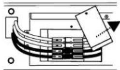
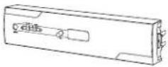
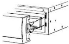
1. Remove the front panel. Remove the rubber end caps and pull up on the latch mechanism. Once the latch mechanism stops,
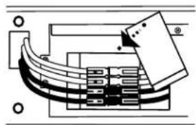
2. Remove the screw from the battery connector security plate to release the battery connector.
natural_image
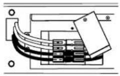
Technical diagram of a mechanical or electrical component with internal channels and mounting holes (no text or symbols)- Disconnect both the red and black connectors.
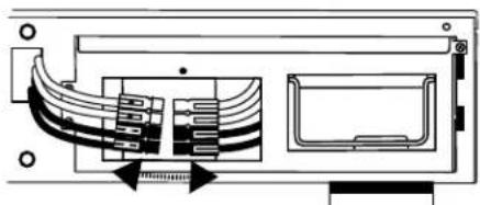
natural_image
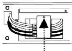
Technical line drawing of a computer drive showing internal components and external casing (no text or labels)- Remove the screws from the battery pack (part number BC-1500) and pull the battery pack out of the unit using the integrated handle.
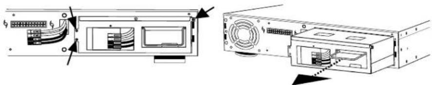
natural_image
Diagram of a computer drive showing front panel, rear panel, and internal components (no text or labels)- Install the new battery pack into the unit. DO NOT ATTEMPT TO REPLACE THE BATTERIES IN THE ORIGINAL BATTERY PACK. IMPROPER INSTALLATION CAN RESULT IN FIRE OR BATTERY LEAKAGE.
natural_image
Pure electrical circuit lines without any symbols- Reconnect the battery cable connectors and the security plate.
WARNING! ALWAYS CONNECT RED to RED and BLACK to BLACK. If the cable connectors do not snap together easily as RED to RED and BLACK to BLACK, NEVER attempt to force them together or flip connectors over resulting in a RED to BLACK combination which will cause electrical sparking, shock, fire or explosion! Call customer service for help.
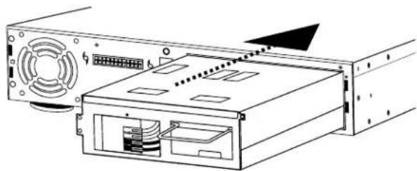
natural_image
Technical line drawing of a computer drive assembly (no text or symbols visible)- Reinstall the front panel per the Front Panel Installation instructions.
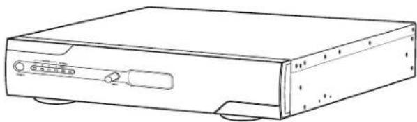
natural_image
Line drawing of a rectangular electronic device with ports and connectors (no text or symbols)F1500-UPS RACK MOUNT INSTALLATION
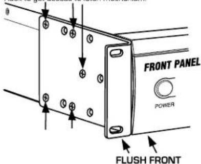
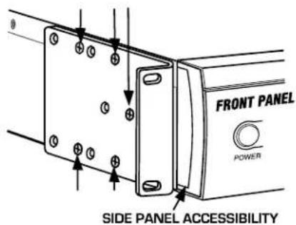
OPTION 1 - FOR FLUSH MOUNT
To mount product in a flush position in relationship with the rack, use the holes as indicated below. Important Note! Product must be removed from the Rack to get access to latch mechanism.
OPTION 2 - TO MOUNT FOR EASY FRONT PANEL REMOVAL
For access to latch mechanism use the holes as indicated below.
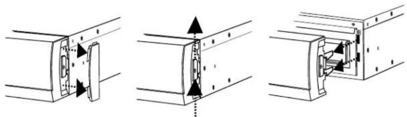
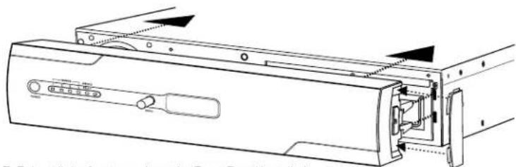
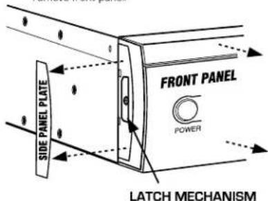
TO REMOVE FRONT PANEL
Remove side panel plates from both ends, push up the latch mechanism, and pull out to remove front panel.
OPERATION
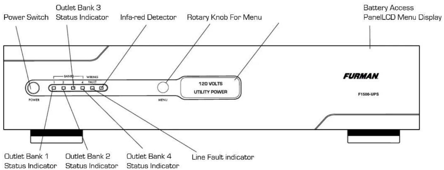
FRONT PANEL DESCRIPTION (See Diagram Of Unit, Page 20)
Power Switch
Press the power button to turn the F1500-UPS ON or OFF.
Menu Navigation Knob
Rotate clockwise to navigate to the next screen, counter-clockwise to return to the previous screen, push to select menu item.
IR Detector
IR Detector, for sampling IR remote control signals.
Removable Battery Access Panel
Easy to remove for battery access and replacement.
FRONT PANEL DISPLAY LED DESCRIPTIONS (See Diagram Of Unit, Page 20)
Status Display
LCD displays status and menu navigation items
Outlet Bank 1 Indicator
Illuminated blue when outlet bank 1 is switched on
Outlet Bank 2 Indicator
Illuminated blue when outlet bank 2 is switched on
Outlet Bank 3 Indicator
Illuminated blue when outlet bank 3 is switched on
Outlet Bank 4 Indicator
Illuminated blue when outlet bank 4 is switched on
Line Fault Indicator
This LED will illuminate in red to warn the user that a wiring problem such as a bad/missing ground or reversed wiring exists within the AC receptacle. If illuminated, disconnect all equipment and contact an electrician to insure outlet is properly wired.
REAR PANEL DESCRIPTION (See Diagram Of Unit, Page 20)
Outlet Bank 1 - Critical Load Outlets
Two battery powered, SMP protected outlets for critical-load equipment insures temporary uninterrupted operation of connected equipment during a power failure.
Outlet Bank 2 - Critical Load Outlets
Two battery powered, SMP protected outlets for critical-load equipment insures temporary uninterrupted operation of connected equipment during a power failure.
Outlet Bank 3 - Non-Critical-Load Outlets
Two battery powered, SMP protected outlets for connected equipment insures temporary uninterrupted operation of connected equipment during a power failure. These outlets will shut off when the batteries drain to a designated level to reserve remaining battery charge for the critical load outlets.
Outlet Bank 4 - Non-Critical-Load Outlets
Two battery powered, SMP protected outlets for connected equipment insures temporary uninterrupted operation of connected equipment during a power failure. These outlets will shut off when the batteries drain to a designated level to reserve remaining battery charge for the critical load outlets.
IR Control Section
Indicator LED's - Indicates status
IR Output Jacks - Standard 1/8" (3.5mm) mono jack for connection to an IR flasher (IR flashers not included)
Circuit Breakers for Overload Protection
Resettable circuit breakers provide optimal overload protection.
RS-232 Serial Communication Port
The serial port allows connection and communication between the F1500-UPS and an automation, media server, or computer system. This allows the installer to program a number of variables including the Critical Load Battery Threshold. See the software documentation for more information.
AC Power Cord
Captive, heavy-duty shielded power cord.
USB to Computer
USB port allows communication between F1500-UPS and computer.
OPERATING MODES
Normal Operation (Utility Power) Mode
When connected to a live power source, the F1500-UPS provides power and is ready to provide protection from under- and over-voltages.
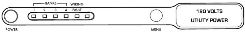
Rotate the navigation dial to scroll through the screens.
Automatic Voltage Regulation (AVR) Mode
Sensitive AVR setting: when receiving input voltages of 96 VAC - 135 VAC, the F1500-UPS supplies a regulated voltage of 120 VAC ± 5%.
Standard AVR setting: when receiving input voltages of 93 VAC - 145 VAC, the F1500-UPS supplies a regulated voltage of 120 VAC ± 10%.
AVR OFF setting: AVR is disabled, no voltage correction.
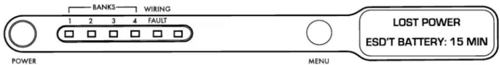
UPS Mode
In the event of a loss of power to the unit, over-voltage, or under-voltage, the F1500-UPS will function as a battery back-up. An audible alarm will sound and the display will indicate the fault (lost power, over-voltage, under-voltage) as well as the number of minutes of battery life remaining.
Setup Mode
The setup menu allows the user to adjust several of the operating parameters of the unit.
Please refer to diagrams on page 58 for a detailed map of the menu structure.
Setup Menu Navigation
Clockwise (CW) rotation of the navigation dial advances the menu to the next item. If the menu is at the last item, SYSTEM INFO, return to Normal Operation Mode. Counter clockwise (CCW) rotation of the navigation dial sends the menu to the previous item. If the menu is at the first item, DISPLAY BRIGHTNESS, the menu will return to Normal Operation Mode. Pressing the navigation dial selects the current menu item. If there is no activity of the navigation dial for 60 seconds, the menu will automatically return to Normal Operation Mode.
Parameter Selection and Adjustment
CW rotation of the navigation dial INCREASES the selected parameter, or advances to the NEXT available value. CCW rotation of the navigation dial DECREASES the selected parameter, or goes back to the PREVIOUS value. Pressing the navigation dial selects the current parameter value. If there is no activity of the navigation dial for 60 seconds, the menu will return to Normal Operation
Mode. If the BACK parameter is selected, return to the menu item selection.
Display Brightness
Display Brightness adjusts the brightness of the display backlight.
Display Scroll Mode
If enabled, the display will automatically advance to the next screen every 5 or 10 seconds.
Display Sleep Mode
With Display Sleep Mode enabled, the display will go to the lowest brightness setting [25%] after the designated time of inactivity of the Navigation Dial {30 SEC, 60 SEC}. The display will return to the set brightness level upon entering Setup Mode, or UPS Mode.
Automatic Regulation Setup
Setup for Automatic Voltage Regulation parameters.
Outlet Bank 3 Setup
Adjusts the battery charge threshold in which Outlet Bank 3 is shut off to conserve power for the critical loads connected to Outlet Bank 1 & 2. If set to OFF, Outlet Bank 3 will shut off immediately when the unit goes into UPS Mode.
Outlet Bank 4 Setup
Adjusts the battery charge threshold in which Outlet Bank 4 is shut off to conserve power for the critical loads connected to Outlet Bank 1 & 2. If set to OFF, Outlet Bank 4 will shut off immediately when the unit goes into UPS Mode.
External Battery
If using the external battery, BAT1500-EXT, set to YES.
IR1 Control Setup
IR1 Control Setup is a two-step process in which the IR1 remote control signal is sampled, and tested by outputting the learned signal on the output jack (See advanced operation section for set-up details).
IR2 Control Setup
IR2 Control Setup is a two-step process in which the IR2 remote control signal is sampled, and tested by outputting the learned signal on the output jack (See advanced operation section for set-up details).
IR Output Delay
IR Output Delay is the time delay before outputting the IR signals from the IR output jacks after the unit goes into UPS mode. IR Output Delay time starts at 0 sec, incremented in 5 sec intervals, with a maximum value of 60 sec.
Setup Buzzer Mode
Change the UPS BUZZER MODE to set it to on or off.
UPS Test Mode
UPS Test Mode places the unit in UPS Mode temporarily to verify that the UPS inverter can adequately supply the connected load.
System Info
Displays the brand, model number and firmware revision.
ADVANCED OPERATION
A connection to a UPS can benefit projector bulbs, server based products, and units with volatile electronic memories found in but not limited to Pro Audio, Broadcast, and High-End Home Theater equipment. The F1500-UPS takes this to the next level with a number of features designed specifically for AC Power back-up applications.
Critical Load Function
One of the user programmable settings in the F1500-UPS software is the Low Battery Non-Critical Load [NCL] Shutoff threshold. This sets the battery capacity level at the point where the NCL outlets are turned off and all remaining battery power is reserved for equipment plugged into the 4 critical load outlets. This value is stored internally by the UPS and is not dependent on having the software running on a computer.
Patent-pending Learning IR Control
The learning IR function lets you program the F1500-UPS to send standby or shut-down commands to components such as DLP ceiling projectors. If the power fails, the projector's lamps are turned off while the F1500-UPS continues providing battery power to the projector's cooling fan. Proper shutdown is ensured and expensive lamps are protected from damage.
NOTE: This function should only be used with discrete IR codes. Programming an On/Off toggle command could result in the
equipment being turned ON during a power failure!
IR Power Failure Operation
The F1500-UPS can learn two IR commands. The learned commands will be transmitted on both output jacks so you have the ability to control 2 different pieces of equipment or use a 2-step macro for one component.
- After a power failure and the selected delay, the IR codes will be sent to both outputs. The IR LED's will flash once per second during the delay time and will stop flashing after the IR code is sent.
- If the delay settings are the same for both IR1 and IR2, the IR2 code will be sent to both outputs 2 seconds after IR1.
- The IR commands will also be transmitted immediately after the battery charge falls below the critical load battery threshold. This ensures that equipment will be shutdown properly if the F1500-UPS's load level is extremely high and the backup time would be less than the selected IR output delay.
- There is no IR output after the power is restored to the system.
To program IR output:
- From the setup menu, turn the Menu Navigation Knob until IR1 Setup is displayed. Push the Menu Navigation Knob to select.
- Turn the Menu Navigation Knob until IR1 Program is displayed.
- The screen will display the message "READY TO SAMPLE REMOTE". Press the button on the remote.
- If the signal was learned, then the screen will display the message "IR1 SAMPLED" and advance to the "TEST IR" screen. Press the navigation knob to test.
- If the signal was not learned, the screen will display the message "IR1 SAMPLE FAIL", then it will return to the IR1 Program screen. Repeat steps 3 and 4.
- To program another IR device, from the Setup menu, turn the Menu Navigation Knob until IR2 Setup is displayed. Follow steps 3-5.
RS-232 Communications Protocol & Command Set
The RS-232 serial interface can be used in the following ways:
- Initial system setup. An installer can use a notebook computer to set the variables within the Power Control software. Once the setup is completed, the notebook computer can be disconnected. All settings are stored in the F1500-UPS.
- Connection to a PC or Network: Functionality is very similar to a standard UPS with a PC. The F1500-UPS can provide continued power to maintain recording capabilities of any number of devices in the event of a black out or brown out. It is also capable of saving open documents and shutting down the PC during extended power failures. This requires a permanent RS-232 connection to the PC and having the Power Control software running in the background on the PC. (Windows based OS only; Mac Energy Saver software compatible)
- Integration with sophisticated automation systems like AMX® and Crestron®: The serial communications command set and protocol is open and is published later in this manual. This information can be used by the automation system programmer for both F1500-UPS control by the automation system and reporting of power events by the F1500-UPS to the automation system.
Command Set/Status Messaging
The following commands are applicable when communicating with your F1500-UPS using the included RS-232 interface. These commands can also be used when directly connecting to the device via Telnet protocol with the BlueBOLT-CV1 interface card (sold separately).
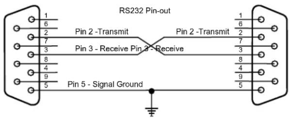
Communications Protocol
Connector Pin-out: Pin 2, Transmit. The F1500-UPS transmits data on this pin.
Pin 3, Receive. The F1500-UPS receives data on this pin.
Pin 5, SG [signal ground].
Baud Rate: 9600bps
Start Bits: 1
Data Bits: 8
Stop Bits: 1
Parity: None
Flow Control: None
Controller Commands
Commands and responses are in the form of ASCII character strings terminated with a carriage return [
Incoming messages (to the F1500-UPS) shall be terminated with one of the following characters: NUL [OOh, OOd], carriage return or line feed.
The F1500-UPS shall discard the incoming message under the following conditions: The message overruns the receiver buffer [32 characters]. No terminating character (NUL,
NOTE: Responses are only transmitted automatically if unsolicited feedback is enabled (!SET_FEEDBACK)
ALL ON
Turns on all outlets. Turn on is immediate with no delay.
Send to UPS: !ALL_ON
If power is not switched off due to low battery conditions
Action: Turn on Outlet Bank 1 & 2
Response from UPS: \$BANK 1 = ON
$$ \text { BANK } 2 = \text { ON } < \text { CR } > $$
If UPS battery level > Shutoff Threshold
Action: Turn on Outlet Bank 3 & 4
Response from UPS: \$BANK 3 = ON
$$ \$BANK 4 = ON< CR> $$
If UPS battery level < Shutoff Threshold
Action: Turn off Outlet Bank 3 & 4
Response from UPS: \$BANK 3 = OFF
$$ \text { BANK 4 } = \text { OFF } < \text { CR } > $$
$$ \text {BATTERY} = \text {charge} $$
Action: Activate Power Button
Response from UPS: \$BUTTON = ON
ALL OFF
Turns off all outlets. Turn off is immediate with no delay.
Send to UPS: !ALL_OFF
Action: All outlets will turn off
Response from UPS: \$BANK 1 = OFF
BANK 2 = OFF
SWITCH OUTLET BANK
Turns a specific outlet bank on or off. Switching is immediate with no delay.
Send to UPS: !SWITCH bank state<CR>
bank = {1, 2, 3, 4}, state = {ON, OFF}
Example: !SWITCH 2 ON<CR>
(turns on outlet bank 2)
If power to bank 1 or 2 is switched
Action: Switch power to Outlet Bank 1 or 2
Response from UPS: $BANK 1 = state<CR>
$BANK 2 = state<CR>
If power to bank 3 or 4 is switched AND battery level > Shutoff Threshold
Action: Switch power to Outlet Bank 3 or 4
Response from UPS: $BANK 3 = state<CR>
$BANK 4 = state<CR>
If UPS battery level > Shutoff Threshold
Action: Turn on Outlet Bank 3 or 4
Response from UPS: $BANK 3 = ON<CR>
$BANK 4 = ON<CR>
If UPS battery level < Shutoff Threshold
Action: Turn off Outlet Bank 3 or 4
Response from UPS: $BANK 3 = OFF<CR>
    $BANK 4 = OFF<CR>
    $BATTERY = charge%<CR>
If power button is OFF and state is changed to ON
Action: Activate Power Button
Response from UPS: $BUTTON = ON<CR>
If entered bank or state are invalid
Response from UPS: $INVALID_PARAMETER<CR>
SET BANK 3 & 4 THRESHOLD
Sets the battery level threshold in which Outlet Bank 3 or 4 shuts off.
Send to UPS: !SET_BATTHRESH bank level
Level is a number between 20 and 100 represents the battery charge level where Outlet Bank 2 is shut off to the reserve remaining battery charge for the equipment connected to Outlet Bank 1. Level shall be rounded up to the nearest interval of 10. Bank is the outlet bank number (3 or 4) to set.
If level is >19 AND level <101
Action: SHUTOFF THRESHOLD will be set to a value between 20 and 100.
Response from UPS: $BTHRESH = level<CR>
If specified level is invalid
Action: No action will be taken
Response from UPS: $INVALID_PARAMETER<CR>
SET BUZZER MODE
With Buzzer Mode ON, the buzzer will sound during UPS Mode.
Send to UPS: !SET_BUZZER mode<CR>
mode = {ON, OFF}
If specified mode is invalid
Action: No action will be taken, UPS will request a valid mode setting
Response from UPS: \$INVALID_PARAMETER
$BUZZER = mode<CR>
SET AVR MODE
Sets AVR (Automatic Voltage Regulation) MODE.
Send to UPS: !SET_AVR mode
mode = {OFF, STANDARD, SENSITIVE}
If specified mode is invalid
Action: No action will be taken, UPS will request a valid mode setting
Response from UPS: \$INVALID_PARAMETER
$AVR = mode<CR>
SET FEEDBACK MODE
Sets the feedback mode to ON (unsolicited) or OFF (polled). When ON, a message will be sent to the controller every time the status of an input (i.e. button), output (i.e. outlet) or power state (i.e. overvoltage) changes. If feedback is OFF, the controller must request status with a query (see Queries section for more details).
Send to UPS: !SET_FEEDBACK mode
mode = {ON, OFF}
If specified mode is invalid
Action: No action will be taken, UPS will request a valid mode setting
Response from UPS: \$INVALID_PARAMETER
$FEEDBACK = mode<CR>
SET LINEFEED MODE
With LINEFEED MODE set, a linefeed character (
Send to UPS: !SET_LINEFEED mode
mode = {ON, OFF}
If specified mode is invalid
Action: No action will be taken, UPS will request a valid mode setting
Response from UPS: \$INVALID_PARAMETER
$LINEFEED = mode<CR>
SET METER BRIGHTNESS
Sets the LCD display and outlet bank indicator brightness.
Send to UPS: !SET_BRIGHT xxx
xxx = {100, 075, 050, 025}
If specified brightness setting is invalid
Action: No action will be taken, UPS will request a valid brightness setting
Response from UPS: \$INVALID_PARAMETER
$BRIGHTNESS = xxx<CR>
SET DISPLAY SCROLL MODE
Sets the LCD display SCROLL mode.
Send to UPS: !SET_SCROLLMODE xxx
xxx = {5SEC, 10SEC, OFF}
If specified display scroll mode is invalid
Action: No action will be taken, UPS will request a valid mode setting
Response from UPS: \$INVALID_PARAMETER
$SCROLL_MODE = xxx<CR>
SET DISPLAY SLEEP MODE
Sets the LCD display.
Send to UPS: !SET_SLEEPMODE xxx
xxx = {30SEC, 60SEC, OFF}
If specified display sleep mode is invalid
Action: No action will be taken, UPS will request a valid mode setting
Response from UPS: \$INVALID_PARAMETER
\$SLEEP_MODE = xxx
RESET FACTORY SETTINGS
Resets all of the custom configuration settings.
Send to UPS: !RESET_ALL
Action: Sets all state variables to the default values
Response from UPS: \$FACTORY SETTINGS RESTORED
SEND QUERIES IDENTIFY
Request that the unit identify itself.
Send Query to UPS: ?ID
Action: Model number and firmware revision will be provided
Response: \$FURMAN
\$F1500-UPS
\$FIRMWARE revision
OUTLET STATUS
Requests the on/off status of the outlet banks.
Send Query to UPS: ?OUTLETSTAT
status = {ON, OFF}
Action: On/off status for outlets will be provided
Response: \$BANK1 = status
\$BANK2 = status
\$BANK3 = status
\$BANK4 = status
POWER STATUS
Requests the status of the input voltage. The responses are the same as Power Fault Status Change.
Send Query to UPS: ?POWERSTAT
Action: Power status messages will be returned
Response: Normal operation = \$PWR = NORMAL
Overvoltage \$PWR = OVERVOLTAGE
Undervoltage \$PWR = UNDERVOLTAGE
Lost Power \$PWR = LOST POWER
Test Mode \$PWR = TEST
POWER
Requests the input and output voltages.
Send Query to UPS: ?POWER
Action: Voltage status messages will be displayed
Response: \$VOLTS_IN = wv
\$VOLTS_OUT = vw
\$WATTS = xxxx
\$VA = xxxx
[xxx is expressed in decimal format]
If the value is less than 100, the hundreds digit is represented with a 0. For example a line voltage of 92VAC would be expressed as: \$VOLTAGE = 092
POWER CYCLE COMMAND USING TELNET PROTOCOL WITH BlueBOLT-CV1
CYCLE Turns an outlet off, then delays before turning it back on.
[NOTE - THIS COMMAND IS ONLY AVAILABLE WHEN USING THE TELNET PROTOCOL WITH THE BlueBOLT-CV1 INTERFACE. IT IS NOT SUPPORTED OVER SERIAL (RS-232) CONNECTION].
Send to UPS [CV-1 card]: #CYCLE bank:delay
Action: Turns off specified outlet bank them waits for delay seconds and finally turns the outlet bank back on.
Response: There are no direct responses from this command, but the outlet status change messages will be sent as the outlet changes state:
\$OUTLETn = status Where n = {1-4} Status = {ON, OFF}
LOAD LEVEL STATUS
Requests the load level, expressed as percentage of maximum.
Send Query to UPS: ?LOADSTAT
Action: Load level will be displayed
Response: \$LOAD = xxx
[xxx is the load level (percentage of maximum load) expressed in decimal format]
If the value is less than 100, the hundreds digit is represented with a 0.
BATTERY LEVEL STATUS
Requests the battery level, expressed as a percentage of maximum (full charge).
Send Query to UPS: ?BATTERYSTAT
Action: Load level will be displayed
Response: \$BATTERY = xxx
[xxx is the battery charge level (percentage of maximum charge) expressed in decimal format]
If the value is less than 100, the hundreds digit is represented with a 0.
LIST CONFIGURATION
Requests a list of all configurable parameters and current settings.
Send Query to UPS: ?LIST_CONFIG
Action: List of configurable parameters and current settings will be displayed
Response: \$BTHRESH = level
\$BUZZER = mode
\$AVR = mode
\$FEEDBACK = mode
\$LINEFEED = mode
\$BRIGHTNESS = xxx
\$SCROLL_MODE = xxx
\$SLEEP_MODE = xxx
VOLTAGE
Requests the input voltage level.
? VOLTAGE (CR)
Response: \$ VOLTS-IN = wv
(where vw is the input voltage)
CURRENT
Requests the output current.
? CURRENT (CR)
Response: \$ CURRENT = ccc
(where ccc is the output current in amps)
LIST OF ALL COMMANDS AND QUERIES
Send Query to UPS: ?HELP
Action: List of all commands and queries will be displayed
Response: !ALL_ON
!ALL_OFF
!SWITCH
!SET_BATTHRESH
!SET_BUZZER
!SET_AVR
!SET_FEEDBACK
!SET_LINEFEED
!RESET_ALL
!SET_BRIGHT<CR>
!SET_SCROLLMODE<CR>
!SET_SLEEPMODE<CR>
?ID<CR> ?OUTLETSTAT<CR>
?POWERSTAT<CR>
?VOLTAGE<CR>
?LOADSTAT<CR>
?BATTERYSTAT<CR>
?LIST_CONFIG<CR>
?HELP<CR>
RESPONSES & MESSAGES
OUTLET STATUS CHANGE CONDITION RESPONSE
Outlet Bank 1 changes state $BANK1 = status<CR>
Outlet Bank 2 changes state $BANK2 = status<CR>
Outlet Bank 3 changes state $BANK3 = status<CR>
Outlet Bank 4 changes state $BANK4 = status<CR>
status = {ON, OFF}
POWER BUTTON
STATUS CHANGE CONDITION RESPONSE
Power Button changes ON/OFF status \$BUTTON = status
status = {ON, OFF}
POWER FAULT
STATUS CHANGE CONDITION RESPONSE
Overvoltage State PWR = OVERVOLTAGE
Power Control Software
Complete Instructions are available by clicking on Help on the Power Control Software welcome screen.
FCC NOTICE
This equipment has been tested and found to comply with the limits for a Class B Digital Device, pursuant to Part 15 of the FCC Rules. These limits are designed to provide reasonable protection against harmful interference in residential installation. This equipment generates, uses, and can radiate radio frequency energy and, if not installed and used in accordance with the instructions, may cause harmful interference to radio communications. However, there is no guarantee that interference will not occur in a particular installation. If this equipment does cause harmful interference to radio or television reception, which can be determined by turning the equipment off and on, the user is encouraged to try to correct the interference by one or more of the following measures:
[1] Reorient or relocate the receiving antenna.
(2) Increase the separation between the equipment and receiver.
(3) Connect the equipment into an outlet on a circuit different from that to which the receiver is connected.
[4] Consult the dealer or an experienced radio/TV technician for help. Any special accessories needed for compliance must be specified in the instruction.
CAUTION: A shielded-type power cord is required in order to meet FCC emission limits and also to prevent interference to the nearby radio and television reception. It is essential that only the supplied power cord be used. Use only shielded cables to connect I/O devices to this equipment.
CAUTION: Any changes or modifications not expressly approved by the guarantee of this device could void the user's authority to operate the equipment.
SERVICE
Please contact Furman Customer Service for information regarding battery replacement.
If you require technical support or equipment service, please contact the Furman Service Department at 877-486-4738. You may also email info@furmansound.com.
All equipment being returned for repair must have a Return Authorization (RA) number. To get an RA number, please call the Furman Service Department.
Before returning any equipment for repair, please be sure that it is adequately packed and cushioned against damage in shipment, and that it is insured. We suggest that you save the original packaging and use it to ship the product for servicing. Also, please enclose a note giving your name, address, phone number and a description of the problem.
3 YEAR LIMITED WARRANTY
SAVE YOUR SALES RECEIPT! Your receipt is your proof of purchase and confirms the product was purchased at an authorized Furman dealer. It will need to be submitted to Furman in order to process any warranty claims. Please contact Furman Customer Service for information regarding 2-year Battery Warranty.
Furman, a brand of Panamax Inc., warrants its F1500-UPS (the "Product") as follows: Furman warrants to the original Purchaser of the Product that the Product sold hereunder will be free from defects in material and workmanship for a period of three year from the date of purchase. If the Product does not conform to this Limited Warranty during the warranty period (as herein above specified), Purchaser shall notify Furman of the claimed defects by calling 877-486-4738. If the defects are of such type and nature as to be covered by this warranty, Furman shall authorize Purchaser to return the Product to Furman headquarters. Warranty claims MUST be accompanied by a copy of the original purchase invoice showing the purchase date. Shipping charges to Furman headquarters must be prepaid by the Purchaser of the product. Furman shall, at its own expense, furnish a replacement Product or, at Furman's option, repair the defective Product. Return shipping charges back to Purchaser will be paid by Furman.
THE FOREGOING IS IN LIEU OF ALL OTHER WARRANTIES, EXPRESS OR IMPLIED, INCLUDING BUT NOT LIMITED TO THE IMPLIED WARRANTIES OF MERCHANTABILITY AND FITNESS FOR A PARTICULAR PURPOSE.
Furman does not warrant against damages or defects arising out of improper or abnormal use of handling of the Product, or against defects or damages arising from improper installation. This warranty shall be cancelable by Furman at its sole discretion if the product is modified in any way without written authorization from Panamax Inc. This warranty also does not apply to Products upon which repairs have been affected or attempted by persons other than pursuant to written authorization by Furman.
THIS WARRANTY IS EXCLUSIVE. The sole and exclusive obligation of Furman shall be to repair or replace the defective Product in the manner and for the period provided above. Furman shall not have any other obligation with respect to the Products or any part thereof, whether based on contract, tort, strict liability or otherwise. Under no circumstances, whether based on this Limited Warranty or otherwise, shall Furman be liable for incidental, special, or consequential damages. This Limited Warranty states the entire obligation of Furman with respect to the Product. If any part of this Limited Warranty is determined to be void or illegal, the remainder shall remain in full force and effect.
SPECIFICATIONS
INPUT
Voltage: 90 - 140 Vac
Frequency: 57 - 63 Hz
AC POWER
Surge Protection: Non-sacrificial SMP (Series Multi-Stage Protection)
Current Rating: 12 A maximum (7.5 A maximum battery load recommended)
Overvoltage Shutoff, fast rise: 150 ± 5 V
Overvoltage Shutoff, slow rise: 140 ± 5 V
Noise Attenuation: 10 dB @ 10kHz, 40 dB @ 100 kHz, 50 dB @ 500kHz
Linear Attenuation Curve: From 0.05 - 100 Ohms line impedance
Automatic Voltage Regulation,
Sensitive Mode Capture Range: 98 - 135 Vac
Automatic Voltage Regulation,
Sensitive Mode Output Range: 120 ± 5%
Automatic Voltage Regulation,
Standard Mode Capture Range: 93 - 145 Vac
Automatic Voltage Regulation,
Standard Mode Output Range: 120 ± 10%
UPS OUTPUT
Voltage: 120 ± 5 V True Sine Wave
Frequency: 60 Hz ± 1%
UPS Output Capacity: 1500VA, 900W @ 0.6pf
UPS Backup Time: 12 minutes at full load, 32 minutes at half load
Transfer Time: < 4ms
Temperature Rating: Units are considered acceptable for use in a
maximum ambient of 40^ C (or “O \~ 40^ C” for ambient operation)
Product: 3.5" H x 19.2" L x 17" W
Weight: 72 lbs
F1500-UPS FRONT PANEL
F1500-UPS REAR PANEL
![Circuit Breakers RS-232 Interface Card [BlueBOLT-CV1 Card Sold Separately] Main Circuit Breaker BANK 4 + NON CRITICAL LOAD BANK 3 + NON CRITICAL LOAD PUSH TO RESET, ISA CRITICAL LOAD BANK 2 + CRITICAL LOAD BANK 1 + CRITICAL LOAD PUSH TO RESET, ISA NONCRITICAL LOAD EXTENSIVE BATTERY OUTLET BANK 4 and 3 Non-critical Load Outlet Bank 2 and 1 Critical Load External Battery Connectors USB Port IR OUTPUT Jacks IR1 IR2 COMMUNICATION CARD 15A PUSH TO RESET MAIN POWER 125 / 12A USB Captive AC Power Cord](/content/2026/04/618595/images/be5347646f7183844dfec89738c24924315293756cf916cb41ad6048aae06da4.jpg)
CARACTÉRISTIQUES DU F1500-UPS DE FURMAN
natural_image
Pure electrical circuit lines without any symbolsnatural_image
Technical diagram of a mechanical or electrical component with curved internal structure and directional arrows (no text or symbols)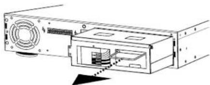
natural_image
Diagram of a computer drive showing fan, ports, and internal components (no text or labels)natural_image
Diagram of a computer drive showing front panel, rear panel, and internal components (no text or labels)natural_image
Pure electrical circuit lines without any symbolsnatural_image
Technical line drawing of a computer drive bay with ports and connectors (no text or symbols)natural_image
Line drawing of a rectangular electronic device with ports and a central switch (no text or symbols)SUPPORT DE CHASSIS ARRIÈRE
OPTION 1 - POUR LE BÂTI AFFLEURANT
Commande : !SET_SLEEPMODE xxx
Mode test \$PWR = TEST
CYCLE DE PUISSANCE DE COMMANDE AVEC TELNET protocole utilisant BlueBOLT-CV1
Envoyer à UPS (CV-1 card): #CYCLE bank:delay
\$OUTLETn = status Where n = {1-8} Status = {ON, OFF}
ÉLECTRICITÉ
$$ ! A L L O F F < C R > $$
$$ ! S W I T C H < C R > $$
$$ ! S E T _ B A T T H R E S H < C R > $$
$$ ! S E T _ B U Z Z E R < C R > $$
!SET_AVR<CR>
!SET_FEEDBACK<CR>
!SET_LINEFEED<CR>
!RESET_ALL<CR>
!SET_BRIGHT<CR>
!SET_SCROLLMODE<CR>
!SET_SLEEPMODE<CR>
?ID<CR>
?OUTLETSTAT<CR>
?POWERSTAT<CR>
?VOLTAGE<CR>
?LOADSTAT<CR>
?BATTERYSTAT<CR>
?LIST_CONFIG<CR>
?HELP<CR>
RÉPONSES ET MESSAGES
CHANGEMENT D'ÉTAT DE LA PRISE CONDITION RÉPONSE
natural_image
Three technical diagrams showing mechanical assembly steps with arrows indicating movement (no text or symbols)natural_image
Pure mechanical diagram showing two configurations of a curved component with internal channels and mounting holes (no text or symbols)natural_image
Technical line drawing of a computer drive showing internal components and external casing (no text or symbols)natural_image
Diagram of a computer drive showing front panel, rear panel, and internal components (no text or labels)natural_image
Pure electrical circuit lines without any symbolsnatural_image
Technical line drawing of a computer drive chassis showing internal components and ports (no text or symbols)natural_image
Line drawing of a rectangular electronic device with a switch and drive slots (no text or symbols)REEMPLAZO DE BATERÍA DEL F1500-UPS
REEMPLAZO DE BATERÍA DEL F1500-UPS
$BATTERY = charge%<CR>
$FEEDBACK = mode<CR>
$LINEFEED = mode<CR>
CONFIGURAR BRILLO DEL MEDIDOR
xxx = {5SEC, 10SEC, OFF}
$SCROLL_MODE = xxx<CR>
CONFIGURAR MODO DE REPOSO DE PANTALLA
xxx = {30SEC, 60SEC, OFF}
$SLEEP_MODE = xxx<CR>
Enviar a: UPS (CV-1 card): #CYCLE bank:delay
\$OUTLETn = status Where n = {1-8} Status = {ON, OFF}
- F1500-UPS UNINTERRUPTIBLE POWER SUPPLY
- FURMAN®
- FURMAN'S F1500-UPS FEATURES
- INTRODUCTION
- SMP (SERIES MULTI-STAGE PROTECTION)
- EVS (EXTREME VOLTAGE SHUTDOWN)
- LIFT (LINEAR FILTERING TECHNOLOGY)
- SAFETY INFORMATION
- IMPORTANT SAFETY INSTRUCTIONS
- INSTALLATION
- COMMUNICATION INTERFACE
- EXTERNAL BATTERY CONNECTORS
- F1500-UPS FRONT PANEL INSTALLATION
- IMPORTANT SAFETY INSTRUCTIONS FOR BATTERY REPLACEMENT
- F1500-UPS BATTERY REPLACEMENT (TO BE PERFORMED BY QUALIFIED SERVICE TECHNICIAN ONLY)
- F1500-UPS RACK MOUNT INSTALLATION
- OPTION 1 - FOR FLUSH MOUNT
- OPTION 2 - TO MOUNT FOR EASY FRONT PANEL REMOVAL
- TO REMOVE FRONT PANEL
- OPERATION
- Power Switch
- Menu Navigation Knob
- IR Detector
- Removable Battery Access Panel
- Status Display
- Outlet Bank 1 Indicator
- Outlet Bank 2 Indicator
- Outlet Bank 3 Indicator
- Outlet Bank 4 Indicator
- Line Fault Indicator
- Outlet Bank 1 - Critical Load Outlets
- Outlet Bank 2 - Critical Load Outlets
- Outlet Bank 3 - Non-Critical-Load Outlets
- Outlet Bank 4 - Non-Critical-Load Outlets
- IR Control Section
- Circuit Breakers for Overload Protection
- RS-232 Serial Communication Port
- AC Power Cord
- USB to Computer
- OPERATING MODES
- Normal Operation (Utility Power) Mode
- Automatic Voltage Regulation (AVR) Mode
- UPS Mode
- Setup Mode
- Setup Menu Navigation
- Parameter Selection and Adjustment
- Display Brightness
- Display Scroll Mode
- Display Sleep Mode
- Automatic Regulation Setup
- Outlet Bank 3 Setup
- Outlet Bank 4 Setup
- External Battery
- IR1 Control Setup
- IR2 Control Setup
- IR Output Delay
- Setup Buzzer Mode
- UPS Test Mode
- System Info
- ADVANCED OPERATION
- Critical Load Function
- Patent-pending Learning IR Control
- IR Power Failure Operation
- To program IR output:
- RS-232 Communications Protocol & Command Set
- Command Set/Status Messaging
- Communications Protocol
- Controller Commands
- ALL ON
- ALL OFF
- SWITCH OUTLET BANK
- SET BANK 3 & 4 THRESHOLD
- SET BUZZER MODE
- SET AVR MODE
- SET FEEDBACK MODE
- SET LINEFEED MODE
- SET METER BRIGHTNESS
- SET DISPLAY SCROLL MODE
- SET DISPLAY SLEEP MODE
- RESET FACTORY SETTINGS
- SEND QUERIES IDENTIFY
- OUTLET STATUS
- POWER STATUS
- POWER
- POWER CYCLE COMMAND USING TELNET PROTOCOL WITH BlueBOLT-CV1
- CYCLE Turns an outlet off, then delays before turning it back on.
- LOAD LEVEL STATUS
- BATTERY LEVEL STATUS
- LIST CONFIGURATION
- VOLTAGE
- CURRENT
- LIST OF ALL COMMANDS AND QUERIES
- RESPONSES & MESSAGES
- OUTLET STATUS CHANGE CONDITION RESPONSE
- POWER BUTTON
- STATUS CHANGE CONDITION RESPONSE
- POWER FAULT
- Power Control Software
- FCC NOTICE
- SERVICE
- YEAR LIMITED WARRANTY
- THE FOREGOING IS IN LIEU OF ALL OTHER WARRANTIES, EXPRESS OR IMPLIED, INCLUDING BUT NOT LIMITED TO THE IMPLIED WARRANTIES OF MERCHANTABILITY AND FITNESS FOR A PARTICULAR PURPOSE.
- SPECIFICATIONS
- INPUT
- AC POWER
- UPS OUTPUT
- CARACTÉRISTIQUES DU F1500-UPS DE FURMAN
- SUPPORT DE CHASSIS ARRIÈRE
- OPTION 1 - POUR LE BÂTI AFFLEURANT
- CYCLE DE PUISSANCE DE COMMANDE AVEC TELNET protocole utilisant BlueBOLT-CV1
- ÉLECTRICITÉ
- RÉPONSES ET MESSAGES
- CHANGEMENT D'ÉTAT DE LA PRISE CONDITION RÉPONSE
- REEMPLAZO DE BATERÍA DEL F1500-UPS
- CONFIGURAR BRILLO DEL MEDIDOR
- CONFIGURAR MODO DE REPOSO DE PANTALLA
Brand : Furman
Model : F1500UPS
Category : Uninterruptible power supply