RR 200 B - Basket Helios - Free user manual and instructions
Find the device manual for free RR 200 B Helios in PDF.


User questions about RR 200 B Helios
0 question about this device. Answer the ones you know or ask your own.
Ask a new question about this device
Download the instructions for your Basket in PDF format for free! Find your manual RR 200 B - Helios and take your electronic device back in hand. On this page are published all the documents necessary for the use of your device. RR 200 B by Helios.
USER MANUAL RR 200 B Helios
natural_image
Metallic mechanical component with a central ribbed structure (no visible text or symbols)

CE
Radial-Rohrventilatoren
InlineVent®
RR..
DEUTSCH
Inhaltsverzeichnis
text_image
Maße in mmInlineVent - Radial-Rohrventilatoren
Baureihen
natural_image
Mechanical assembly diagram showing a cylindrical component with two directional arrows indicating flow or movement (no text or symbols present)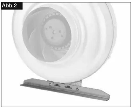
natural_image
Close-up of a white industrial fan or impeller component mounted on a metal bracket (no visible text or symbols)D
Abb.3
text_image
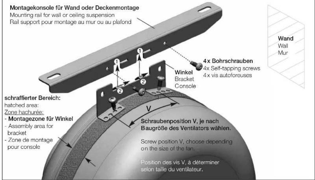
Montagekonsole für Wand oder Deckenmontage Mounting rail for wall or ceiling suspension Rail support pour montage au mur ou au plafond schraffierter Bereich: hatched area: Zone hachurée: - Montagezone für Winkel - Assembly area for bracket - Zone de montage pour console 4x Bohrschrauben 4x Self-tapping screws 4x vis autoforeuses Winkel Bracket Console Schraubenposition V, je nach Baugröße des Ventilators wählen. Screw position V, choose depending on the size of the fan. Position des vis V, à déterminer selon taille du ventilateur.
WARNUNG

WARNUNG

text_image
L N PE L N PE92524 001 SS-508 13.10.03
KAPITEL 8
Please keep this manual for reference with the unit! Print-No.:
natural_image
Metallic mechanical component with a central ribbed structure (no visible text or symbols)

CE
Centrifugal in-line fans
InlineVent®
RR..
ENGLISH
Table of contents
CHAPTER 1. SAFETY ...... Page 1
1.0 Important information Page 1
1.1 Warning instructions Page 1
1.2 Safety instructions ...... Page 1
1.3 Application Page 1
1.4 Personnel qualification Page 2
1.5 Functional safety – Emergency operation Page 2
1.6 Product service life Page 2
CHAPTER 2. GENERAL INFORMATION ...... Page 2
2.0 Warranty claims – Exclusion of liability Page 2
2.1 General information Page 2
2.2 Shipping Page 2
2.3 Receipt Page 2
2.4 Storage Page 2
2.5 Performance data Page 2
2.6 Noise data Page 2
2.7 Air-flow direction and direction of rotation Page 3
2.8 Protection against contact Page 3
2.9 Motor protection Page 3
2.10 Condensation Page 3
CHAPTER 3. TECHNICAL DATA Page 3
3.0 InlineVent RR.. type overview Page 3
3.1 Technical data Page 3
3.2 Accessories Page 4
CHAPTER 4. FUNCTION ...... Page 4
4.0 Functional description RR.... Page 4
CHAPTER 5. USER MAINTENANCE ...... Page 4
5.0 User maintenance Page 4
CHAPTER 6. INSTALLATION Page 5
6.0 Scope of delivery/Design Page 5
6.1 Installation preparation Page 5
6.2 Installation Page 5
6.3 Electrical connection / Start-up Page 6
6.4 Operation Page 6
CHAPTER 7. FUNCTION FOR INSTALLER ...... Page 6
7.0 Functional description RR.... Page 6
7.1 Wiring diagram SS-934.1 Page 7
7.2 Wiring diagram SS-508 Page 7
CHAPTER 8. SERVICING AND MAINTENANCE Page 8
8.0 Servicing and maintenance Page 8
8.1 Fault causes Page 8
8.2 Standstill and disposal Page 9
UK
CHAPTER 1
SAFETY
1.0 Important information
In order to ensure complete and effective operation and for your own safety, all of the following instructions should be read carefully and observed.
This document should be regarded as part of the product and as such should be kept accessible and durable to ensure the safe operation of the fan. All plant-related safety regulations must be observed.
DANGER
WARNING
CAUTION
1.1 Warning instructions
The accompanying symbols are safety-relevant prominent warning symbols. All safety regulations and/or symbols in this document must be absolutely adhered to, so that any risks of injury and dangerous situations are avoided!
DANGER
1.2 Safety instructions
Special regulations apply for use, connection and operation; consultation is required in case of doubt. Further information can be found in the relevant standards and legal texts.

Protective glasses
Serves to protect against eye injuries.

Ear protectors
Serves to protect against all kinds of noise.

Protective clothing
Primarily serves to protect against contact with moving parts. Do not wear rings, chains or other jewellery.

Protective gloves
Protective gloves serve to protect the hands against rubbing, abrasions, cuts or more profound injuries, as well as contact with hot surfaces.

Protective footwear
Protective footwear serves to protect against heavy falling parts and from slipping on slippery surfaces.

Hair net
The hair net primarily serves to protect long hair against contact with moving parts.
With regard to all work on the fan, the generally applicable safety at work and accident prevention regulations must be observed!
- The following must be observed before all cleaning, maintenance and installation work or before opening the terminal compartment:
- Isolate the device from the mains power supply and secure against being switched on again!
- The rotating parts must first come to a standstill!
-
Once the rotating parts come to a standstill, a waiting time of 5 min. must be observed, as dangerous voltages may be present due to internal capacitors even after disconnection from the mains!
-
All plant-related safety regulations must be observed! If applicable, further country-specific regulations must also be observed!
- Protection against contact must be ensured pursuant to DIN EN 13857 in the installed condition (see section 2.8)!
Contact with rotating parts must be avoided.
UK
- A uniform inflow and free outlet must be ensured!
- When using a vented fire place (chimney) in a ventilated room, there must be sufficient supply air for all operating conditions (consult chimney sweep).
The current locally applicable regulations and laws must be observed!
1.3 Application
- Normal use:
The centrifugal in-line fans RR for conveying normal or slightly dusty (particle size < 10 m), less aggressive and humid air, in moderate climates and in the range of their performance curves, see Helios sales documents / internet. Operation is only admissible with fixed installation within buildings. The maximum admissible media and ambient temperature can be found on the type plate.
- Reasonably foreseeable misuse:
The fans are not suitable for operation under difficult conditions, such as high levels of humidity, aggressive media, long standstill periods, heavy contamination, excessive loads due to climatic, technical or electronic influences. The same applies for the mobile use of fans (vehicles, aircraft, ships, etc.). Usage under these conditions is only possible with release approval from Helios, as the standard version is not suitable in this case.
- Improper, prohibited use:
Any use other than the intended use is not permitted! The conveying of solid matter or solid matter content >10 m in air and liquid is not permitted. Transport media, which affect the materials of the fan, and abrasive media are not permitted. Use in explosive atmospheres is not permitted! Outside operation of the fan is not permitted.
DANGER
1.4 Personnel qualification
⚠️ DANGER!
The electrical connection and start-up as well as the installation, servicing and maintenance of the fan must only be carried out by qualified electricians.
Centrifugal in-line fans RR can be used by children over the age of 8 as well as persons with physical, sensory, or mental disabilities or lack of experience and knowledge, if they are supervised or instructed with regard to the safe use of the unit and they understand the resulting risks. Children must not play with the unit. Cleaning or user maintenance must not be carried out by unsupervised children.
1.5 Functional safety – Emergency operation
When using the fan in an important supply function, the plant is to be designed so that emergency operation is automatically guaranteed in case of fan failure. Suitable solutions are, for example,: parallel operation of two less powerful units with a separate electric circuit, standby fan, alarm systems and emergency ventilation systems.
1.6 Product service life
The motors are equipped with maintenance-free, permanently lubricated ball bearings. Under normal operating conditions, they should be replaced after approximately 40,000 operating hours, standstill or long storage periods of more than 2 years.
2.0 Warranty claims - Exclusion of liability
All versions of this documentation must be observed, otherwise the warranty shall cease to apply. The same applies to liability claims against Helios. The use of accessory parts, which are not recommended or offered by Helios, is not permitted. Any possible damages are not covered by the warranty. Changes and modifications to the unit are not permitted and lead to a loss of conformity, and any warranty and liability shall be excluded in this case.
2.1 Certificates - Guidelines
If the product is installed correctly and used to its intended purpose, it conforms to all applicable EU guidelines at its date of manufacture.
2.2 Shipping
The fan is packed ex works in such a way that it is protected against normal transport strain. Carry out the shipping carefully. It is recommended to leave the fan in the original packaging.
2.3 Receipt
The shipment must be checked for damage and correctness immediately upon delivery. If there is any damage, promptly report the damage with the assistance of the transport company.
If complaints are not made within the agreed period, any claims could be lost.
2.4 Storage
When storing for a prolonged time, the following steps are to be taken to avoid damaging influences: Motor protection by dry, airtight and dust-proof packaging (plastic bag with desiccant and humidity indicators). Vibration-free, water-tight and constant-temperature storage at a temperature in the range -20 °C to +40 °C.
In case of a storage period of more than three months or motor standstill, maintenance must be carried out before
CHAPTER 2
GENERAL INFORMATION
UK
NOTE
start-up according to chapter 8. In case of reshipment (above all, over longer distances; e.g. by sea), it must be checked whether the packaging is suitable for the form and route of transport. Damages due to improper transportation, storage or putting into operation are not liable for warranty.
2.5 Performance data
The unit type plate gives an indication of the mandatory electrical values; which must be coordinated with the local supply network. The fan performances* were established on a test stand according to DIN EN ISO 5801.
NOTE!
The maximum current in regular operation may deviate or be higher than the nominal current! Observe unit type plate data!
2.6 Noise data
Noise data that refers to certain distances apply to free field conditions. With regard to installation, the sound pressure level can differ significantly from the catalogue data, as it is highly dependent on the installation conditions, i.e. on the absorption capability of the room and the room size among other factors.
2.7 Air-flow direction and direction of rotation
The RR fans have a fixed direction of rotation and air-flow direction (they are not reversible), which is indicated by the arrows on the device. The air-flow direction can be determined during installation.
2.8 Protection against contact
- Centrifugal in-line fans RR are not delivered with fan protection guards as standard. Depending on the installation conditions, protection against contact may be necessary on the suction and/or discharge side. Corresponding protection guards are available as accessories.
- Fans which are protected by their installation method (e.g. installation in ventilation ducts or closed assemblies) do not require protection guards if the plant provides the necessary level of safety. Please note that the operator is responsible for complying with the current standard and can be held liable for accidents as a consequence of missing protection systems.
2.9 Motor protection
All models have thermal contacts wired in series with the motor windings which automatically switch off and then restart again after cooling down.
NOTE!
Triggered thermal contacts indicate incorrect operating conditions, the cause of which must be addressed. If the thermal contacts are triggered frequently (standstill), the fan must be inspected by a specialist according to chapter 1.4.
2.10 Condensation
If the fan is used intermittently, especially in a humid and warm environment, or if variations in temperature occur, condensation may build up in the motor and draining off must be ensured. In case of condensation in the ducting and fan casing appropriate measures must be taken during installation (water sack, drainage line). Under no circumstances must the motor come into contact with water.
CHAPTER 3
TECHNICAL DATA
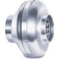
3.0 InlineVent RR.. type overview
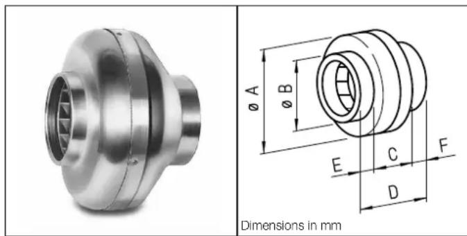
InlineVent – centrifugal in-line fans Series
RR 100 A Ref. no. 5653
RR 100 C Ref. no. 5654
RR 125 C Ref. no. 5655
RR 160 B Ref. no. 5656
RR 160 C Ref. no. 5657
RR 200 A Ref. no. 5658
RR 200 B Ref. no. 5659
RR 250 A Ref. no. 5652
RR 250 C Ref. no. 5660
RR 315 Ref. no. 5920
| ∅ A ∅ | B C D E F | ||||||
| RR 100 A | 243 99 | 136 188 | 26 | 26 | |||
| RR 100 C | 243 99 | 136 188 | 26 | 26 | |||
| RR 125 C | 243 124 | 134 188 | 27 | 27 | |||
| RR 160 B | 271 159 | 133 195 | 30 | 32 | |||
| RR 160 C | 345 159 | 164 226 | 30 | 32 | |||
| RR 200 A | 345 199 | 160 228 | 33 | 35 | |||
| RR 200 B | 345 199 | 160 228 | 33 | 35 | |||
| RR 250 A | 345 249 | 160 228 | 33 | 35 | |||
| RR 250 C | 345 249 | 160 228 | 33 | 35 | |||
| RR 315 | 402 314 | 185 257 | 32 | 40 | |||
Energy-efficient, backward curved, high-performance centrifugal plastic impeller (Type RR 315: galvanised sheet steel)
UK
3.1 Technical data
Pipe connection ∅ [mm] 100 – 315* Alternating current 1 - Protection category IP 44 Voltage/frequency 230 V, 50 Hz Protection class I Power consumption [W] 40 – 200* Weight approx. kg 2,9 – 6* Nominal current [mA] 180 – 970* Delivery volume [m3/h] 250 – 1260*
*Values from the smallest to the largest size
3.2 Accessories
The use of accessories not offered or recommended by Helios is not permitted. Any potential damage is not covered by warranty.
| Pipe clamps BM.. - | ||
| Mounting bracket | MK.. | - |
| Backdraught shutter | RSKK/RSK | - |
| Outside wall cover flap | VK.. | - |
| Outside wall cover grille | G / RAG.. | - |
| Protection guard | SGR | - |
| Electronic speed controller (recessed mounting) | ESU.. | - |
| Electronic speed controller (surface mounting) | ESA.. | - |
| Transformer speed controller 5-stage | TSW.. - | |
| Speed switch | DS.. | for types RR 100 C, 125C, 160 B, 160C, 200A, 250A |
| Flexible sound attenuator | FSD.. | - |
| Warm water heater battery | WHR | - |
| Flexible ventilation ducts | ALF.. | - |
| Temp. control system for electric heating battery EHR-R.. | EHR-R.. | - |
| Air filter cassette | LFBR.. | - |
Duct system:
All Helios components fit standard duct . For example, rigid spiral ducts, flexible aluminium or plastic ducts can be used. The relevant fire-protection regulations must be observed if more than two stories of a building are connected.
CHAPTER 4
TECHNICAL DATA
NOTE
CHAPTER 5
USER MAINTENANCE
CHAPTER 6
INSTALLATION
ATTENTION

ATTENTION

4.0 Functional description RR..
The centrifugal in-line fans RR can be controlled in different speed stages by means of a speed control unit. Depending on the type, operation in two stages is also possible.
NOTE!
In case of strong vibrations and/or odours, maintenance must be carried out by a specialist according to chapter 1.4.
5.0 User maintenance
The centrifugal in-line fans RR.. are maintenance-free, there are no user maintenance provisions.
All of the following information and instructions are intended solely for authorised electricians!
6.0 Scope of delivery/Design
The centrifugal in-line fans RR consist of a casing, impeller, electric motor and the associated mounting of the motor in the casing. There is a terminal box for connection to the mains power supply on the outside. The fans are delivered as fully assembled units. Leave the RR unit in the packaging until installation in order to prevent any possible damage and contamination. during transport and on site.
ATTENTION
You can cut or scrape yourself due to sharp edges. Wear protective gloves when unpacking!
6.1 Installation preparation
ATTENTION
You can cut or scrape yourself due to sharp edges. Wear protective gloves when checking unhindered running of impeller!
The fan is delivered as a complete unit, i.e. ready for connection, as standard. It can be installed in any position. The installation and start-up of the fan should take place after the completion of all other works and after the final cleaning, in order to prevent damage and contamination of the ventilation unit.
After the removal of packaging and the start of installation, the following points must be checked:
– is there any transport damage,
- broken or bent parts
– free movement of the impeller
UK
6.2 Installation
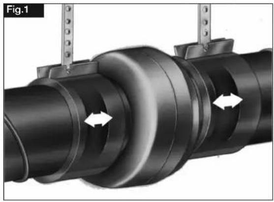
The prevention of structure-borne sound transmission must be ensured during installation. In this respect, e.g. use pipe clamps BM.. (Fig.1) (see also Accessories, section 3.2) for connections in pipelines.
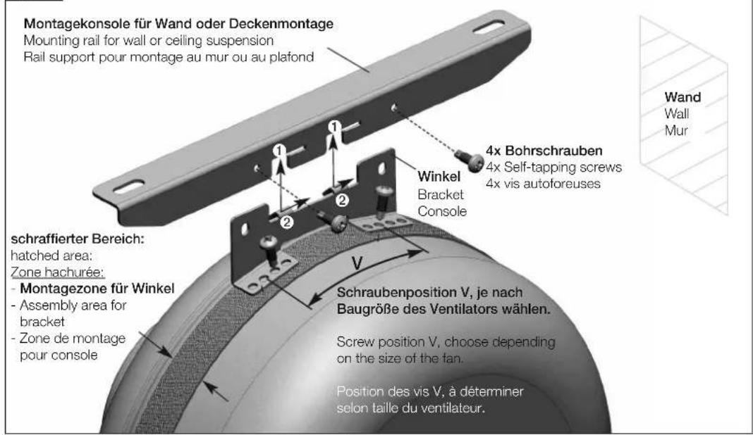
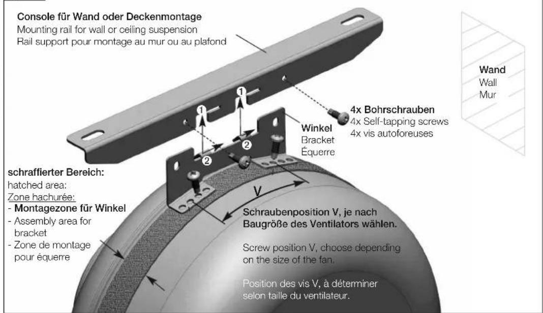
The mounting bracket MK 4 (Fig.2/3) (see also Accessories, section 3.2) forms a simple and practical means for attaching the fan to wall or ceiling elements. An elastic pad between the wall and MK is also provided for the prevention of structure-borne sound transmission. With regard to pipe installation, it must be ensured that there is a sufficiently long straight pipe section before and after the fan, as otherwise significantly reduced performance and noise level increases can be expected.
NOTE
NOTE!
Full fan performance can only be achieved with free inflow and outflow.
Sufficient motor cooling must be ensured, so that there is a minimum air flow area of 20 % for the fan cross-section.
natural_image
Mechanical assembly diagram showing a cylindrical component with two directional arrows indicating movement or force (no text or symbols present)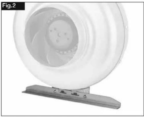
natural_image
Close-up of a white industrial fan or impeller component mounted on a metal base (no visible text or symbols)Fig.3
text_image
Montagekonsole für Wand oder Deckenmontage Mounting rail for wall or ceiling suspension Rail support pour montage au mur ou au plafond schraffierter Bereich: hatched area: Zone hachurée: - Montagezone für Winkel - Assembly area for bracket - Zone de montage pour console Winkel Bracket Console 4x Bohrschrauben 4x Self-tapping screws 4x vis autoforeuses Schraubenposition V, je nach Baugröße des Ventilators wählen. Screw position V, choose depending on the size of the tan. Position des vis V, à déterminer selon taille du ventilateur. Wand Wall MurUK
WARNING
WARNING

6.3 Electrical connection / Start-up
⚠ WARNING!
Touching live parts will lead to electric shock.
Isolate the unit from the mains power supply before connection!
⚠ WARNING!
The rotating impeller can crush fingers.
Ensure protection against contact before start-up!
- The electrical connection and initial start-up must only be carried out by qualified electricians according to the information in the attached wiring diagrams.
- All relevant standards, safety regulations (e.g. DIN VDE 0100), as well as the technical connection conditions of energy suppliers are to be adhered to!
- A multipole mains section switch/isolator, with a minimum contact opening of 3 mm (VDE 0700 T1 7.12.2/EN 60335-1) is mandatory!
– Network configuration, voltage and frequency must be consistent with the rating plate information. - Check the waterproofing of the connection cable and tight clamping of the strands.
- Metal cable screws must not be used when connecting to plastic terminal boxes.
- Insert the supply line so that no water can get in along the cable in case of water exposure.
- Check designated use of fan
– Compare mains voltage to rating plate data - Check fan for solid mounting and professional electrical installation
- Check all parts for tightness, particularly screws, protection guards. Do not loosen screws in the process!
- Check free movement of the impeller. Wear protective gloves when checking unhindered running of impeller!
- Compare power consumption to rating plate data
- Check protective conductor connection
6.4 Operation
In order to ensure the proper functioning of the fan, the following must be checked regularly:
- Formation of dust or dirt deposits in the casing or on the motor and impeller
If excessive vibration or odours occur, maintenance must be carried out according to the instructions in chapter 8.
CHAPTER 7
FUNCTION FOR INSTALLER
NOTE
NOTE
7.0 Functional description RR..
The centrifugal in-line fans are speed controllable by means of voltage reduction. Power adjustment through voltage reduction can be carried out using phase control devices or transformers (TSW..). When using electronic actuators or controllers (ESU../ESA.), electromagnetic motor noise (humming) may occur in the low speed range. This is not the case when using transformer controllers. With regard to noise-critical installations, this solution is preferred.
A minimum speed/voltage, which also depends on on-site resistance, wind pressure, etc., must be complied with for sufficient motor cooling and ensuring functionality.
With regard to the calculation of the control units, it must be noted that there may be current peaks in the variance. The control units must therefore be dimensioned according to our technical data. Suitable control units are offered as accessories.
NOTE!
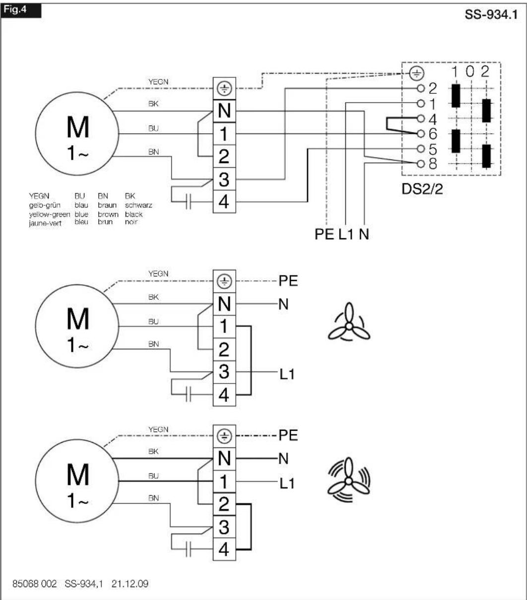
With regard to fan types RR 100 C to 160 C, RR 200 A and RR 250 A, wo speed operation is also possible using the speed switch and on/off switch DS 2/2 (Accessories).
NOTE!
The use of third party products, especially other electronic devices, can lead to functional problems, the destruction of the controller and/or fan. If control units are used, which have not been approved by Helios, all warranty and liability claims shall lapse.
UK
7.1 Wiring diagram SS-934.1 for types RR 100 C, 125 C, 160 B, 160 C, 200 A, 250 A
text_image
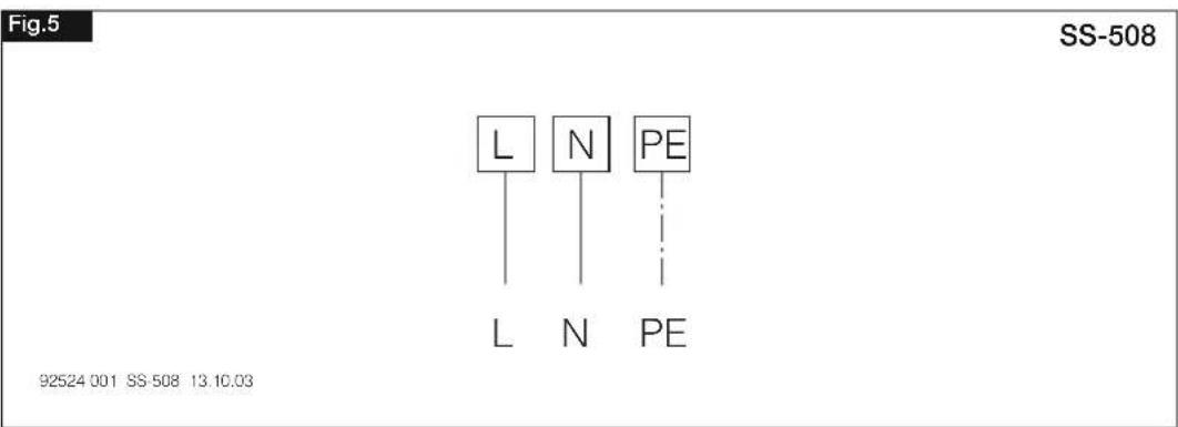
Fig.4 SS-934.1 M 1~ YEGN BK BU BN N 1 2 3 4 DS2/2 PE L1 N YEGN GEIO-grün yellow-green jaune-vert BU blau blue BLU BN BN BN BK braun brown black nor M 1~ YEGN BK BU BN N 1 2 3 4 PE L1 M 1~ YEGN BK BU BN N 1 2 3 4 PE L1 M 1~ YEGN BK BU BN N 1 2 3 47.2 Wiring diagram SS-508 for types RR 100 A, 200 B, 250 C, 315
text_image
Fig.5 SS-508 L N PE L N PE 92524 001 SS-508 13.10.03UK
CHAPTER 8
SERVICING AND MAINTENANCE
WARNING

8.0 Servicing and maintenance
⚠ WARNING!
Touching live parts will lead to electric shock.
Before any servicing and maintenance work, isolate the fan from the mains power supply and protect against being switching on again!
⚠ WARNING!
The rotating impeller can crush fingers.
Before any servicing and maintenance work, isolate the unit from the mains power supply and protect against being switching on again!
– In principle, the units are maintenance-free, there are no user maintenance provisions.
Nevertheless, all necessary maintenance work must be carried out by qualified electricians!
- Excessive deposits of dirt, dust, grease, etc. on the impeller, motor, protection guard and, above all, between the housing and the impeller, are not permitted, as these can lead to an unbalance in the impeller, overheating of the motor or the blocking of the impeller. In such cases, the unit must be cleaned
– In cases of longer periods of standstill, maintenance must be carried out when the unit is restarted.
The following must be checked:
- Secure attachment of the fan to the subsurface / system, replace in case of doubt
- Remove contaminant deposits
- Mechanical damage, disconnect unit, replace damaged parts
- Tight fit of screw connections, do not loosen screws in the process!
- Casing quality (cracks, brittleness of the plastic)
• Free movement of the impeller, impeller does not move freely, see Fault causes 8.2
Wear protective gloves when checking unhindered running of impeller!
- Bearing noises
• Vibrations – see Fault causes 8.2 - Current consumption according to type plate – see Fault causes 8.2
8.1 Cleaning
⚠ WARNING!
An insulation/installation faults may result in electric shock!
Before cleaning, isolate the fan from the mains power supply and protect against being switching on again!
WARNING
WARNING

⚠ WARNING!
The unexpected rotating impeller can crush fingers.
Before cleaning, isolate the fan from the mains power supply and protect against being switching on again!
– Clean casing and impeller with a damp cloth
– The motor must not come into contact with water!
- Do not use aggressive cleaning agents that could damage the paintwork!
– High pressure cleaners or water jets are not permitted!
8.2 Fault causes
| Fault Causes Solution | ||
| Fan does not start – No | voltage Check mains voltage | Check connection according to wiring diagram |
| - Impeller blocked Clear blockage, clean, replace if necessary | ||
| - Motor blocked Contact Helios customer services | ||
| Fan does not turn (no longer turns) | - Mains voltage failure Check mains voltage | |
| - Thermal contact (TK) has triggered | Automatic restart after cooling. Check transport media, ambient temperature | |
| - Fuse has tripped | See "Fuse has tripped" | |
| - Impeller blocked or contaminated | Clear blockage, clean, replace impeller if necessary | |
| Fuse has tripped | - Shorted coil in motor | Contact Helios customer services |
| - Supply line or connection damaged | Replace parts, replace motor if necessary (Contact Helios customer services) | |
| - Connected incorrectly | Check, modify connection | |
| Vibrations | - Contamination Clean | |
| - Attachment-related resonance | Check or repair attachment | |
| Abnormal noises | - Grinding impeller | Clean impeller, replace if necessary |
| - Bearing damage | Contact Helios customer services | |
| - Mechanical damage | Carry out maintenance | |
| Fan no longer performing (speed) | - Insufficient air delivery | Check/clear inflow and outflow |
| - Incorrect voltage | Check/modify connection | |
| - Bearing damage | Contact Helios customer services | |
| - Contamination Clean | ||
| - Insufficient backflow | Widen backflow openings | |
UK

WARNING

8.3 Standstill and disposal
⚠ WARNING
When dismantling, live parts can be exposed, which can result in electric shock if touched. Before dismantling, isolate the unit from the mains power supply and protect against being switching on again!
Parts and components of the fan, whose service life has expired, e.g. due to wear and tear, corrosion, mechanical load, fatigue and/or other effects that cannot be directly discerned, must be disposed of expertly and properly after disassembly in accordance with the national and international laws and regulations. The same also applies to auxiliary materials in use. Such as oils and greases or other substances. The intended and unintended further use of worn parts, e.g. impellers, rolling bearings, filters, etc. can result in danger to persons, the environment as well as machines and systems. The corresponding operator guidelines applicable on-site must be observed and used.

Please keep this manual for reference with the unit! Print-No.:
natural_image
Metallic mechanical component with a central ribbed structure (no visible text or symbols)

CE
1.4 Qualification du personnel
⚠️ DANGER!
natural_image
Metallic industrial component with a flanged top and internal structure (no visible text or symbols)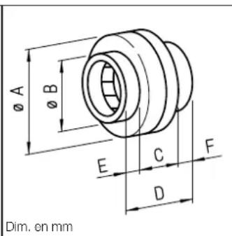
text_image
Ø A Ø B E C F D Dim. en mmInlineVent RR
Séries
natural_image
Mechanical assembly diagram showing a cylindrical component with two white arrows indicating directional movement or force, mounted on a metal frame (no text or symbols present)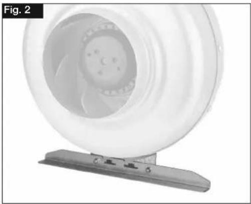
natural_image
Close-up of a white industrial fan or impeller component mounted on a metal base, labeled 'Fig. 2' in the top-left corner (no other text or symbols visible)Fig. 3
text_image
Console für Wand oder Deckenmontage Mounting rail for wall or ceiling suspension Rail support pour montage au mur ou au plafond schraffierter Bereich: hatched area: Zone hachurée: - Montagezone für Winkel - Assembly area for bracket - Zone de montage pour équerre 4x Bohrschrauben 4x Self-tapping screws 4x vis autoforeuses Winkel Bracket Équerre Schraubenposition V, je nach Baugröße des Ventilators wählen. Screw position V, choose depending on the size of the fan. Position des vis V, à déterminer selon taille du ventilateur.F

AVERTISSEMENT

AVERTISSEMENT

Please keep this manual for reference with the unit! Print-No.: