M1120 - Basket Helios - Free user manual and instructions
Find the device manual for free M1120 Helios in PDF.


User questions about M1120 Helios
0 question about this device. Answer the ones you know or ask your own.
Ask a new question about this device
Download the instructions for your Basket in PDF format for free! Find your manual M1120 - Helios and take your electronic device back in hand. On this page are published all the documents necessary for the use of your device. M1120 by Helios.
USER MANUAL M1120 Helios
INSTALLATION AND OPERATING INSTRUCTIONS NO. 19050.005
NOTICE DE MONTAGE ET D'UTILISATION N° 19050.005
natural_image
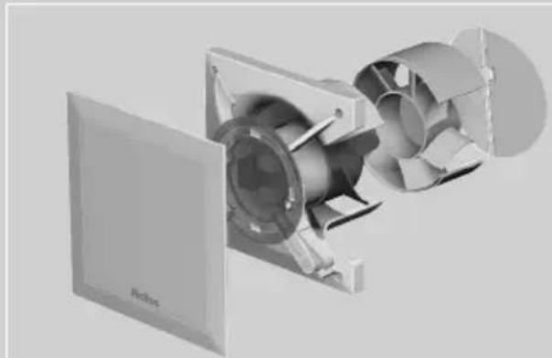
3D cutaway view of a mechanical fan assembly with no visible text or symbolsultraSilence
Technology by Helios


IP 45


natural_image
Diagram showing a device with a panel and its internal structure, labeled Abb.4 (no text or symbols on the diagram itself)Please keep this manual for reference with the unit! Print-No.:
INSTALLATION AND OPERATING INSTRUCTIONS NO. 19050.005
UK
text_image
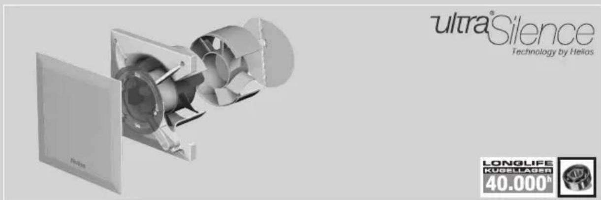
ultra®Silence Technology by Helios LONGLIFE KUGELLAGER 40.000hIP 45


1.0 Important information Page 1
1.1 Warning instructions ...... Page 1
1.2 Safety instructions....Page 1
1.3 Warranty claims - exclusion of liability Page 2
1.4 Certificates - guidelines Page 2
1.5 Shipping Page 2
1.6 Receipt Page 2
1.7 Storage Page 2
1.8 Application Page 2
1.9 Performance data Page 3
1.10 Noise data Page 3
CHAPTER 2. GENERAL OPERATING INSTRUCTIONS ......Page 3
2.0 Personnel qualification....Page 3
2.1 Protection against contact Page 3
2.2 Motor protection device Page 3
CHAPTER 3. TECHNICAL DATA/DIMENSIONS Page 3
3.0 Type overview MiniVent M1/1....Page 3
3.1 Technical data....Page 3
3.2 Accessories Page 4
3.3 Product service life Page 4
3.4 Dimensions Page 4
CHAPTER 4. FUNCTION ......Page 4
4.0 Functional description M1/100/120 Page 4
CHAPTER 5. CLEANING/DISMANTLING Page 5
5.0 Cleaning Page 5
5.1 Dismantling of the facia Page 5
CHAPTER 6. INSTALLATION Page 6
6.0 Scope of delivery/Design Page 6
6.1 Preparation for wall or ceiling installation (surface mounted) Page 6
6.2 Installation Page 6
6.3 Electrical connection....Page 8
6.4 Connection of the supply line / Start-up Page 8
6.5 Mounting Page 9
6.6 Operation Page 10
CHAPTER 7. FUNCTION FOR INSTALLER ......Page 10
7.0 Functional description for M1/100/120 Page 10
CHAPTER 8. SERVICING AND MAINTENANCE ......Page 11
8.0 Servicing and maintenance Page 11
8.1 Fault causes Page 12
8.2 Standstill and disposal Page 12
UK
CHAPTER 1
GENERAL INFORMATION
1.0 Important information
In order to ensure complete and effective operation and for your own safety, all of the following instructions should be read carefully and observed.
This document should be regarded as part of the product and as such should be kept accessible and durable to ensure the safe operation of the fan. All plant-related safety regulations must be observed.

DANGER

WARNING

CAUTION
1.1 Warning instructions
The accompanying symbols are safety-relevant prominent warning symbols. All safety regulations and/or symbols in this document must be absolutely adhered to, so that any risks of injury and dangerous situations are avoided!

DANGER
1.2 Safety instructions
Special regulations apply for use, connection and operation; consultation is required in case of doubt. Further information can be found in the relevant standards and legal texts.
⚠️ With regard to all work on the fan, the generally applicable safety at work and accident prevention regulations must be observed!
- All electrical work, as well as installation, servicing and maintenance of the fan must only be carried out by qualified electricians!
- The following must be observed before all cleaning, installation, servicing and maintenance work or before opening the terminal compartment:
- Isolate the device from the mains power supply and secure against being switched on again!
- The rotating parts must first come to a standstill!
-
Once the rotating parts come to a standstill, a waiting time of 3 min. must be observed, as dangerous voltages may be present due to internal capacitors even after disconnection from the mains!
-
All plant-related safety regulations must be observed!
If applicable, further country-specific regulations must also be observed! - A uniform inflow and free outlet must be ensured!
- When using a vented fire place (chimney) in a ventilated room, there must be sufficient supply air for all operating conditions (consult chimney sweep). The current locally applicable regulations and laws must be observed!
- MiniVent M1/100/120 mini fans can be used by children over the age of 8 as well as persons with physical, sensory, or mental disabilities or lack of experience and knowledge, if they are supervised or instructed with regard to the safe use of the unit and they understand the resulting risks. Children must not play with the unit. Cleaning or user maintenance must not be carried out by unsupervised children.
1.3 Warranty claims - exclusion of liability
All versions of this documentation must be observed, otherwise the warranty shall cease to apply. The same applies to liability claims against Helios. The use of accessory parts, which are not recommended or offered by Helios, is not permitted. Any possible damages are not covered by the warranty. Changes and modifications to the unit are not permitted and lead to a loss of conformity, and any warranty and liability shall be excluded in this case.
1.4 Certificates - guidelines
If the product is installed correctly and used to its intended purpose, it conforms to all applicable EU guidelines at its date of manufacture.
1.5 Shipping
The fan is packed ex works in such a way that it is protected against normal transport strain. Carry out the shipping carefully. It is recommended to leave the fan in the original packaging.
1.6 Receipt
The shipment must be checked for damage and correctness immediately upon delivery. If there is any damage, promptly report the damage with the assistance of the transport company. If complaints are not made within the agreed period, any claims could be lost.
1.7 Storage
When storing for a prolonged time, the following steps are to be taken to avoid damaging influences: Motor protection by dry, airtight and dust-proof packaging (plastic bag with desiccant and humidity indicators). Vibration-free, water-tight and constant-temperature storage at a temperature in the range -20 °C to +40 °C.
In case of a storage period of more than three months or motor standstill, maintenance must be carried out before start-up according to chapter 4. In case of reshipment (above all, over longer distances; e.g. by sea), it must be checked whether the packaging is suitable for the form and route of transport. Damages due to improper transportation, storage or putting into operation are not liable for warranty.
1.8 Application
Normal use:
The MiniVent M1/100/120 mini fans are suitable for conveying normal or slightly dusty (particle size < 10 μm), less aggressive and humid air, in moderate climates and in the range of their performance curves, see Helios sales documents / internet. Operation is only admissible with fixed installation within buildings. The maximum admissible media and ambient temperature is 40 °C. MiniVent M1/150 ... mini fans correspond to protection category IP45, protection class II and may be installed in area 1 wet rooms according to VDE 0100 part 701.
- Reasonably foreseeable misuse:
The fans are not suitable for operation under difficult conditions, such as high levels of humidity, aggressive media, long standstill periods, heavy contamination, excessive loads due to climatic, technical or electronic influences. The same applies for the mobile use of fans (vehicles, aircraft, ships, etc.). Usage under these conditions is only possible with release approval from Helios, as the standard version is not suitable in this case.
- Improper, prohibited use:
Any use other than the intended use is not permitted! The conveying of solid matter or solid matter content > 10μm in air and liquid is not permitted. Transport media, which affect the materials of the fan, and abrasive media are not permitted. Use in explosive atmospheres is not permitted!
UK
1.9 Performance data
The unit type plate gives an indication of the mandatory electrical values; which must be coordinated with the local supply network. The fan performances* were established on a test stand according to DIN EN ISO 5801.
1.10 Noise data
Noise data that refers to certain distances apply to free field conditions. With regard to installation, the sound pressure level can differ significantly from the catalogue data, as it is highly dependent on the installation conditions, i.e. on the absorption capability of the room and the room size among other factors.
CHAPTER 2
GENERAL OPERATING INSTRUCTIONS
2.0 Personnel qualification
The electrical connection and start-up as well as installation, servicing and maintenance of the fan must only be carried out by qualified electricians.
- MiniVent M1/100/120 mini fans can be used by children over the age of 8 as well as persons with physical, sensory, or mental disabilities or lack of experience and knowledge, if they are supervised or instructed with regard to the safe use of the unit and they understand the resulting risks. Children must not play with the unit. Cleaning or user maintenance must not be carried out by unsupervised children.
2.1 Protection against contact
MiniVent M1/100/120 mini fans do not require a protection guard, as they meet the requirements of DIN EN 60335-2-80 section 20.101.
2.2 Motor protection device
The motors of the MiniVent M1/100/120 are equipped with thermo contacts, which are wired in series with the winding, and which automatically switch off and on again after cooling.
CHAPTER 3
TECHNICAL DATA / DIMENSIONS
3.0 Type overview MiniVent M1/1..
M1/100 equipped with two speeds Ref.No. 6171
M1/120 equipped with two speeds Ref.No. 6360
3.1 Technical data
M1/100
Impeller ∅ [mm] 92 Electrical supply line NYM-O 3 x 1.5 mm²
Alternating current 1\~ Protection category IP 45 (water jet protection)
Voltage/frequency 230 V, 50 Hz Protection class II
Power consumption [W] 9/5 Weight approx. [kg] 0,8
Rated current [mA] 0.06/0.04 Speed [1/min] 2650/2250
Flow volume [m^3/h] 90/75
M1/120
Impeller ∅ [mm] 111 Electrical supply line NYM-O 3 x 1.5 mm ^2
Alternating current 1\~ Protection category IP 45 (water jet protection)
Voltage/frequency 230 V, 50 Hz Protection class II
Power consumption [W] 13/10 Weight approx. [kg] 1,05
Rated current [mA] 0.09/0.08 Speed [1/min] 2350/2050
Flow volume [m^3/h] 170/150
UK
3.2 Accessories
MVB Operating/speed switch 0-1-2 Ref.No. 6091
WES 100 Wall installation kit Ref.No. 0717
WES 120 Wall installation kit Ref.No. 0486
MF 100 Mounting flange Ref.No. 6188
TWH 100 Telescopic wall sleeve Ref.No. 6352
TWH 120 Telescopic wall sleeve Ref.No. 6353
MBR Mounting cover strip Ref.No. 0281
3.3 Product service life
This unit is designed for a product service life of at least 40,000 h, in case of S1 operation with maximum power in the maximum permissible ambient temperature.
3.4 Dimensions
M1/100 M1/120
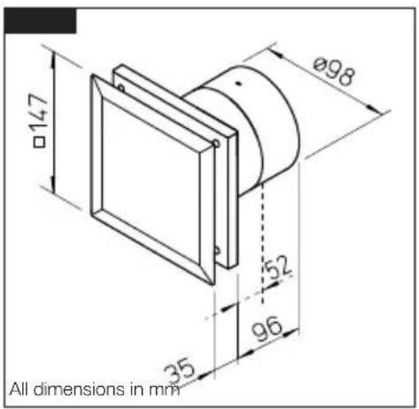
text_image
Ø98 147 52 35 96 All dimensions in mm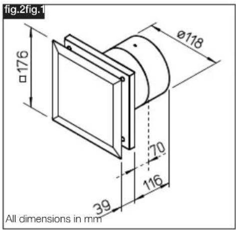
text_image
fig.2fig.1 Ø118 Ø176 70 39 116 All dimensions in mmCHAPTER 4
FUNCTION
4.0 Functional description M1/100/120
The M1/100/120 MiniVent mini fan can be selectively operated with a commercially available light switch in stage 1 or stage 2. By controlling the speed with the on/off switch MVB (Accessories), the M1/100/120 MiniVent can be used in two settings.
CHAPTER 5
CLEANING/ DISMANTLING

DANGER
5.0 Cleaning
△ The safety instructions in chapter 1.2 must be observed!
- Before cleaning, isolate the fan from the mains power supply and secure against being switched on again!
– Clean facia and visible casing parts with a damp cloth - Do not use aggressive, paint-damaging cleaning agents!
– High pressure cleaners or jet water is not permitted!
5.1 Dismantling of the facia
Procedure:
- Isolate fan from mains power supply and secure against being switched on again!
- By pressing the snap-in hooks, the facia ① can be unlocked and removed (fig. 3/4).
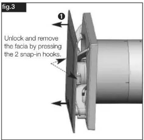
text_image
fig.3 Unlock and remove the facia by pressing the 2 snap-in hooks.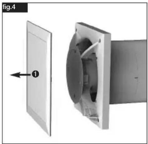
natural_image
Diagram showing a device with a panel and its internal structure, labeled 'fig.4' (no text or symbols on the diagram itself)All subsequent information and instructions are intended solely for authorised electricians!
CHAPTER 6
INSTALLATION
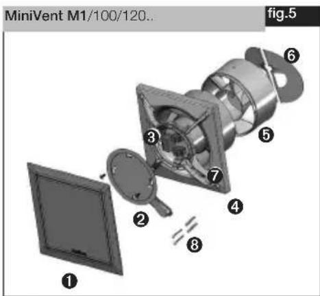
6.0 Scope of delivery/Design
Leave the delivery unit in its box until installation. Check that the fan is in good condition and has not been damaged in transit.
text_image
MiniVent M1/100/120.. fig.5 ① ② ③ ④ ⑤ ⑥ ⑦ ⑧①Facia
②Terminal compartment cover incl. 2x fastening screws
③Control board
④ Plastic casing with impeller
⑤Guide vane removable at reduced installation depth
⑥Back draught shutter removable
⑦Cable grommet
⑧Assembly kit
2x screws including plugs for wall mounting
6.1 Preparation for wall or ceiling installation (surface mounted)
The safety instructions in chapter 1.2 must be observed!
The fan is delivered as a complete unit, i.e. ready for connection, as standard. The installation and start-up of the fan should take place after the completion of all other works and after the final cleaning, in order to prevent damage and contamination of the ventilation unit.
After the removal of packaging and the start of installation, the following points must be checked:
– is there any transport damage.
- broken or bent parts
- freewheeling of the impeller
6.2 Installation
The M1/100/120 MiniVent is designed for direct wall installation. The housing must not be deformed or warped during installation, and the flat structure of the installation surface must be ensured. The fans must only be installed on sufficiently solid and stable subsurfaces with suitable fastening materials. Sufficient backflow must be ensured! If applicable, observe instructions in DIN 1946-6.
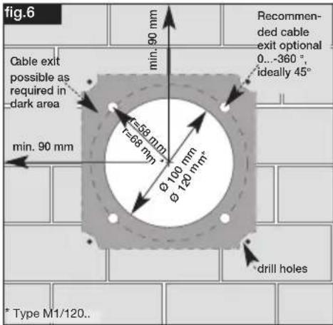
1. Cable exit from the wall:
- The location of the cable outlet varies in the dark area (fig.6).
- Distance to the duct centre depending on cable exit 58/68* mm with a variable position under the casing.
- For a simple assembly an exit is recommended as shown (turnable by 90^ in each case).
The optimal position is 45^ each if the cable exit is directly at the position of the cable grommet.
UK
- Duct inside diameter M1/100 = 100 mm or M1/120 = 120 mm and distance to room corners: at least 90 mm.
- With regard to surface mounted cabling, the side entry knockout for the cable (fig.9, Pos ①) in the casing must be broken out!
- The connection cable and the control line must be stored so that no water can get in along the cable in case of water exposure. The cables must not be placed over sharp edges!
text_image
fig.6 Cable exit possible as required in dark area min. 90 mm -558 mm 1-68 mm Ø 100 mm Ø 120 mm* Recommended cable exit optional 0...360 °, ideally 45° drill holes * Type M1/120..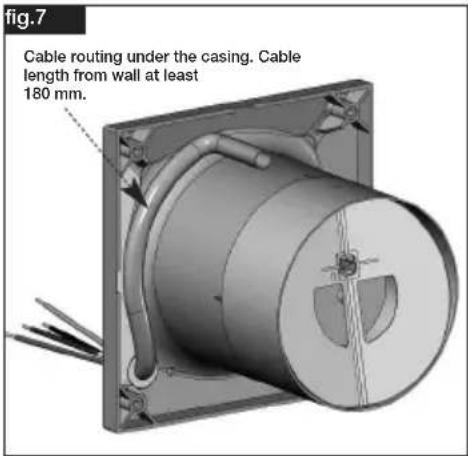
text_image
Fig.7 Cable routing under the casing. Cable length from wall at least 180 mm.2. Drill holes:
Set casing against the wall, mark the holes and drill. Fasten with at least 2 screws and plugs.
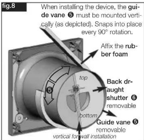
3. Back draught shutter and guide van
- When installing the device, the guide vane must be mounted vertically (fig. 8). Snaps into place every 90^ rotation.
- Affix the rubber foam (scope of delivery) before final assembly (fig.8)
text_image
Fig.8 When installing the device, the guide vane ⑤ must be mounted vertically (as depicted). Snaps into place every 90° rotation. Affix the rubber foam top Back draught shutter ⑥ removable bottom Guide vane ⑤ removable vertical for wall installation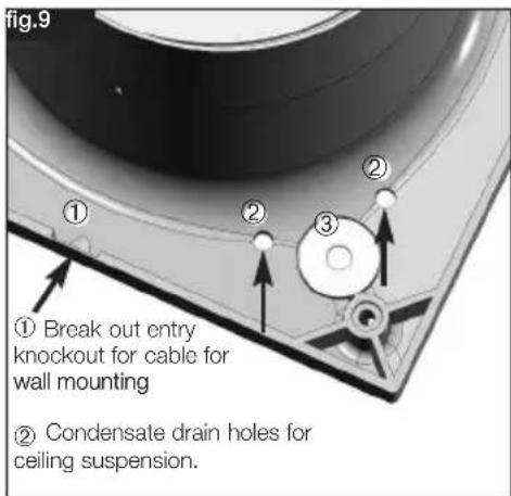
text_image
fig.9 ① Break out entry knockout for cable for wall mounting ② Condensate drain holes for ceiling suspension.4. Mounting flange MF 100 (Accessories)
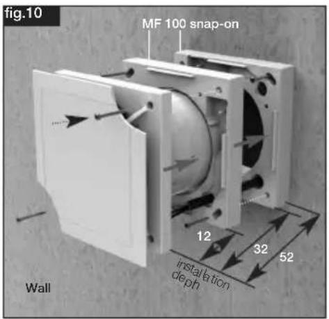
If there are space restrictions in ceilings, in thin walls and in narrow shafts. Attach MF 100 to the wall or ceiling at a suitable angle (any number possible). Then fasten the fan to the MF 100 with the provided screws (fig. 10/11). Also suitable for mounting a pull-cord switch (Accessories).
text_image
fig.10 MF 100 snap-on Wall 12 32 52 installation depth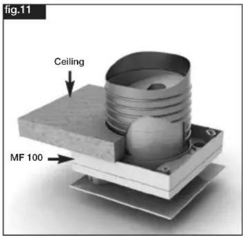
text_image
fig.11 Ceiling MF 100
DANGER
6.3 Electrical connection
⚠ The safety instructions in chapter 1.2 must be observed!
- The electrical connection and initial start-up are to be carried out in accordance with the relevant wiring diagram and are only to be carried out by a certified electrician.
- All relevant standards, safety regulations (e.g. DIN VDE 0100), as well as the technical connection conditions of energy suppliers are to be adhered to!
- A multipole mains section switch/isolator, with a minimum contact opening of 3 mm (VDE 0700 T1 7.12.2 / EN 60335-1) is mandatory!
- Network configuration, voltage and frequency must be consistent with the rating plate information.
6.4 Connection of the supply line / Start-up
- A commercially available NYM line must be used, maximum diameter 11 mm
- Pre-pierce grommet with round tool or pierce directly with supply line (fig.9, Pos ③)
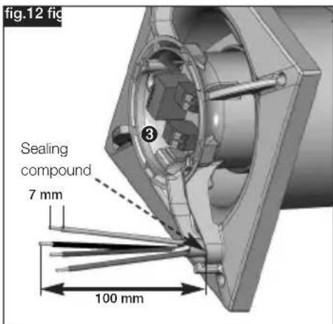
- Remove sheath to 100 mm. Strip wires to 7 mm (fig.12)
- Carefully push cable through the grommet
- Place wires in the cable channel and connect according to wiring diagram (page 10)
- Check the waterproofing of the connection cable and tight clamping of the strands
- If the grommet does not evenly enclose the sheathed cable once the supply line is installed, the grommet must be additionally sealed, e.g. with Silicone N. Otherwise, the IP protection will expire
- The connection cable and the control line must be stored so that no water can get in along the cable in case of water exposure. The cables must not be placed over sharp edges!
- Check designated use of fan
- Compare mains voltage to rating plate data
- Check fan for solid mounting and professional electrical installation

WARNING
WARNING
- Check freewheeling of the impeller
- Check all parts for tightness, particularly screws, protection guards. Do not loosen screws in the process!
- Check fan for vibration and noise during test run
- Compare power consumption to rating plate data
text_image
fig.12 fig Sealing compound 7 mm 100 mm- Length of single conductors 100 mm
- Stripping length 7 mm
- Strip sheathed cable flush with cable duct
text_image
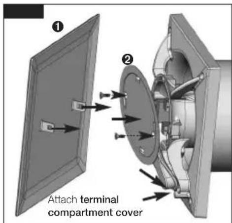
① ② Attach terminal compartment cover- Align terminal compartment cover ② with groove, attach and screw to casing.
- Then snap-in facia ①.
6.5 Mounting
text_image
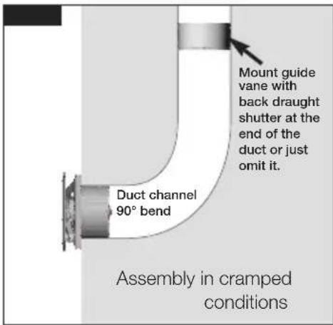
Mount guide vane with back draught shutter at the end of the duct or just omit it. Duct channel 90° bend Assembly in cramped conditions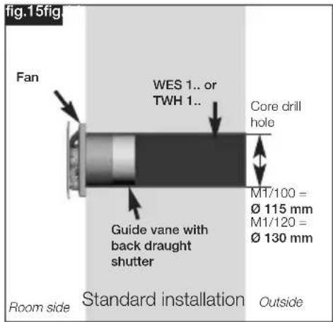
text_image
Fig.15fig. Fan WES 1.. or TWH 1.. Core drill hole MT/100 = Ø 115 mm M1/120 = Ø 130 mm Guide vane with back draught shutter Room side Standard installation OutsideUK
WARNING
CHAPTER 7
FUNCTION FOR INSTALLER
6.6 Operation
The safety instructions in chapter 1.2 must be observed!
In order to ensure the smooth functioning of the fan, the following must be checked on a regular basis:
- Appearance of dust or contaminant deposits in the housing or on the motor and impeller
– Freewheeling of the impeller
– Occurrence of excessive vibration and noise
In case of problems with one of the aforementioned points, maintenance must be carried out according to the instructions in chapter 8.
7.0 Functional description M1/100/120 (Standard model)
The M1/100/120 MiniVent mini fan can be selectively operated with a commercially available light switch in stage 1 or stage 2.
By controlling the speed with the on/off switch MVB (Accessories only for M1/100/120), the M1/100 can be used in two settings (75/90 m ^3 /h) or the M1/120 can be used in two settings (150/170 m ^3 /h).
7.1 Circuit diagram overview for M1/100/120 (Standard model)
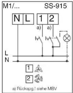
a) With regard to the connec-
tion of terminal 1 or 2, there is reverse voltage at the other respective disconnected terminal.
Room lighting or glow lamps for operating displays, must only be connected via bipolar switch.
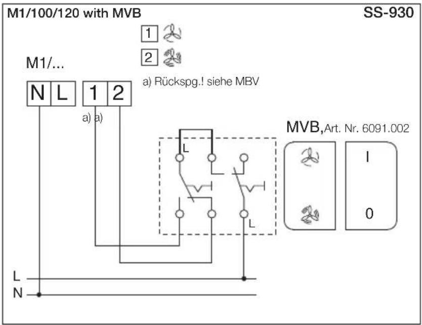
8.0 Servicing and maintenance
△ The safety instructions in chapter 1.2 must be observed!
- Before any work, isolate the fan from the mains power supply and secure against being switched on again!
- The units are basically maintenance-free, there is no provision for user-maintenance. Nevertheless, all necessary maintenance work must be carried out by trained electricians!
- Excessive deposits of dirt, dust, grease, etc. on the impeller, motor, protection guard and, above all, between the housing and the impeller, are not permitted, as these can lead to an unbalance in the impeller, overheating of the motor or the blocking of the impeller.
- In cases of longer periods of standstill, maintenance must be carried out when the unit is restarted.
The following must be checked:
- Secure mounting of the fan to the subsurface / system, replace in case of doubt
- Remove contaminant deposits
- Mechanical damage, decommission unit, replace damaged parts
- Tightness of screw connections, do not loosen screws in the process!
• Housing surface coating (e.g. rust, paint defects) - Freewheeling of the impeller -> Is the impeller not running freely- see Fault causes8.1
- Bearing noises
• Vibrations- see Fault causes 8.1
• Power consumption according to type plate - see Fault causes 8.1
8.1 Fault causes
The safety instructions in chapter 1.2 must be observed!
| Error/fault | Causes | Troubleshooting |
| Fan does not start | - No voltage | Check mains voltageCheck connection according to circuit diagram |
| - Impeller blocked | Clear blockade, clean, replace impeller if neces. | |
| - Motor blocked | Contact Helios customer services | |
| Fuse blows | - Short-circuited coil in motor | Contact Helios customer services |
| - Supply line/connection damaged | Replace parts, replace motor if necessary(Contact Helios customer services) | |
| - Connected incorrectly | Check connection, change | |
| Vibrations | - Contamination | Clean |
| - Mounting-related resonance | Check/repair mounting | |
| Abnormal noises | - Grinding impeller | Clean impeller, replace if necessary |
| - Bearing damage | Contact Helios customer services | |
| - Mechanical damage | Carry out maintenance | |
| Fan does not perform (speed) | - Insufficient air supply | Check/clear inflow and outflow |
| - Incorrect voltage | Check/change connection | |
| - Bearing damage | Contact Helios customer services | |
| - Contamination | Clean | |
| - Insufficient backflow | Enlarge backflow openings |
8.2 Standstill and disposal
△ The safety instructions in chapter 1.2 must be observed!
Parts and components of the fan, whose service life has expired, e.g. due to wear and tear, corrosion, mechanical load, fatigue and/or other effects that cannot be directly discerned, must be disposed of expertly and properly after disassembly in accordance with the national and international laws and regulations. \~The same also applies to auxiliary materials in use. Such as oils and greases or other substances. The intended and unintended further use of worn parts, e.g. impellers, rolling bearings, filters, etc. can result in danger to persons, the environment as well as machines and systems. The corresponding operator guidelines applicable on-site must be observed and used.
Notes:
UK

Please keep this manual for reference with the unit! Print-No.:
natural_image
3D cutaway view of a mechanical fan assembly with no visible text or symbolsultraSilence Technology by Helios


IP 45


CE
Mini-ventilateur
Helios MiniVent
M1/100/120
6.2 Installation Page 6
Puissance absorbée [W] 13/10 Poids approx. [kg] 1,05
natural_image
Diagram showing a device with a panel and its internal structure, labeled as Fig. 4 (no text or symbols on the diagram itself)Please keep this manual for reference with the unit! Print-No.: