
DR120A3000 - Dehumidifier HONEYWELL - Free user manual and instructions
Find the device manual for free DR120A3000 HONEYWELL in PDF.
| Product Type | Whole-House Dehumidifier |
| Brand | Honeywell Home |
| Model | DR120A3000 |
| Dehumidification Capacity | 120 pints/day (56.8 L/day) at 80°F, 60% RH |
| Maximum Recommended Area | Up to 3,120 ft² (290 m²) |
| Dimensions (H × W × D) | 657 × 521 × 375 mm |
| Weight | 43.1 kg |
| Power Supply | 120 VAC, 60 Hz, 7.3 A |
| Power Consumption | 7.3 A (24 VAC transformer, 0.85 A) |
| Energy Efficiency | 2.9 L/kWh |
| Filter Type | MERV 11 (Part No. 50070171-002) |
| Duct Connection | 10 in (254 mm) round inlet and outlet |
| Drain | 3/4 in female NPT fitting |
| Refrigerant | R-410A, 30 oz (850 g) |
| Operating Temperature | 1.1°C to 57.2°C (34°F to 135°F) |
| Operating Humidity | 0 to 99% RH |
| Maximum Airflow | 400 CFM (680 m³/h) |
| Compressor | Rotary, 9.4 kBtu/h |
| Warranty | 5 years |
| Certifications | Energy Star, ETL, CSA |
| Maintenance | Annual filter replacement |
| Safety | Ground fault circuit interrupter recommended; optional float switch |
Frequently Asked Questions - DR120A3000 HONEYWELL
User questions about DR120A3000 HONEYWELL
0 question about this device. Answer the ones you know or ask your own.
Ask a new question about this device
Download the instructions for your Dehumidifier in PDF format for free! Find your manual DR120A3000 - HONEYWELL and take your electronic device back in hand. On this page are published all the documents necessary for the use of your device. DR120A3000 by HONEYWELL.
USER MANUAL DR120A3000 HONEYWELL

INCLUDED IN THIS BOX
A1
natural_image
Exterior view of a black industrial air duct unit with ventilation ducts and a circular vent (no text or symbols visible)(or)
natural_image
Exterior view of a black industrial air duct unit with ventilation ducts (no text or symbols visible)B
©
D
E
OPTIONAL CONTROLS SOLD SEPARATELY

E2
E3
E4
E
Tools required to install DR90A3000/DR120A3000
Dehumidifier
3/8" hex drive
Drill or duct cutting tool
Wire stripper/cutter
Scissors or utility knife
Standard screwdriver
T25 Torx screwdriver
Duct tape
1/2" diameter drain line (8')
1/2" drain clamps (2)
10" round duct and starter collar
3/4" male NPT to drain line adaptor (1/2" Dia. recommended)
Options
1/2" drain p-trap (may be required by local code)
Drain pan
Float switch or water sensor
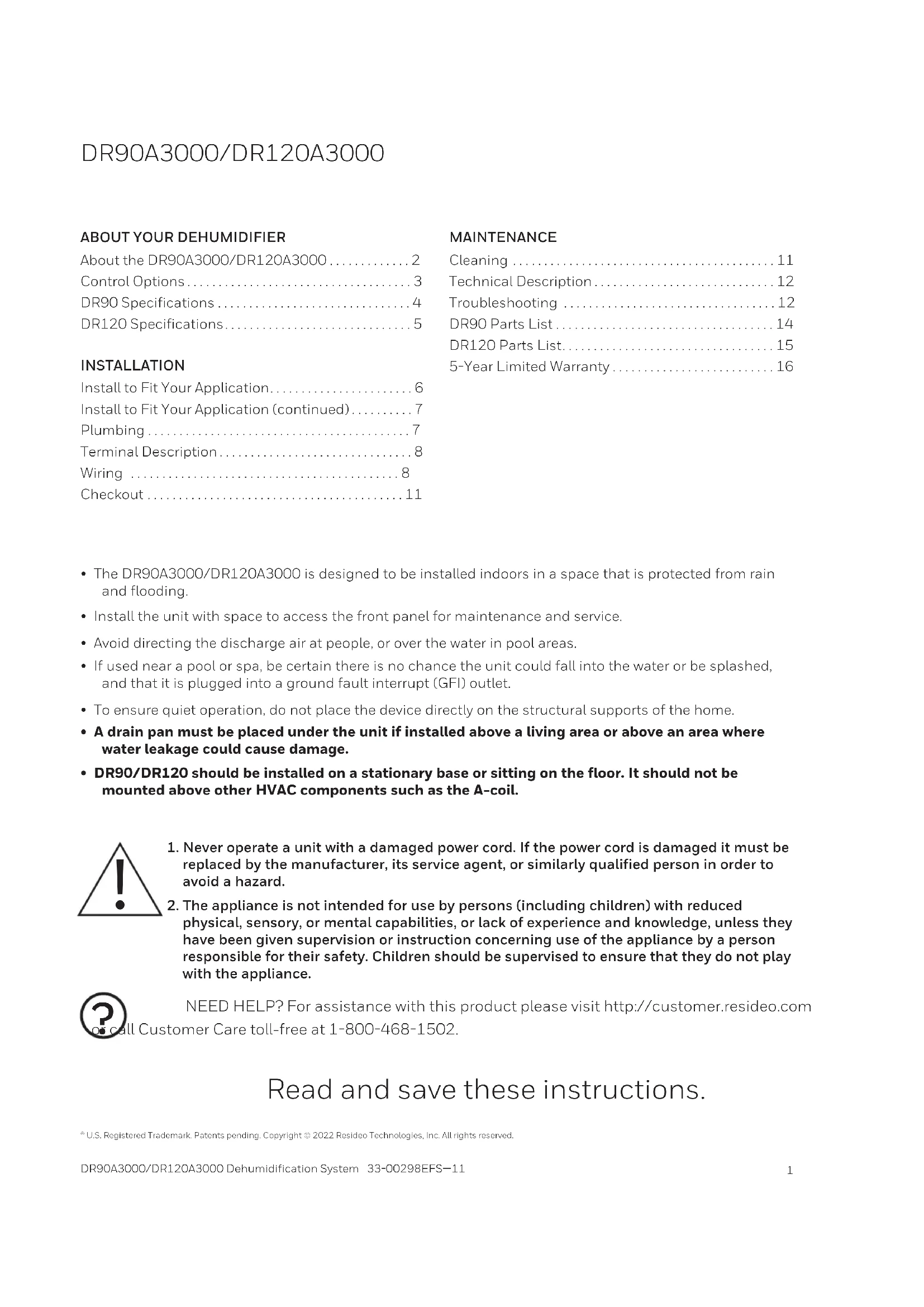
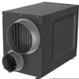
A1 DR90A3000 (1) or
A2 DR120A3000 (1)
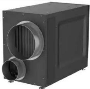
B MERV 11 Filter (1)
C Filter Door (2)
D Installation Guide
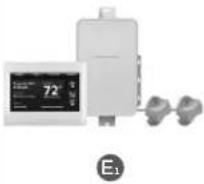
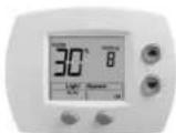
E _1 Prestige™ IAQ Kit
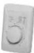
E2 H8908 Manual Dehumidistat
E3 VisionPRO™ Smart or VisionPRO RedLINK
H6062 HumidiPRO Digital Humidity Control
E5 T10 Pro Smart
Installation Checklist
Included in This Box
A1 DR90A3000 (1) or
A2 DR120A3000(1)
B MERV 11 Filter (1)
C Filter Door (2)
D Installation Guide
Control Options (Sold separately)
E1 Prestige IAQ Kit
E2 H8908 Manual Dehumidistat
E3 VisionPRO™ Smart or VisionPRO™ RedLINK
E4 H6062 HumidiPRO Digital Humidity Control
E5 T10 Pro Smart
Tools Required (Not Supplied)
- 3/8" hex drive
- Drill or duct cutting tool
- Wire stripper/cutter
- Scissors or utility knife
- Standard screwdriver
• T25 Torx screwdriver
- Duct tape
• 10" round duct and starter collar
• 18-22 gauge, 5 band thermostat wire
- 1/2" diameter drain line (8')
- 1/2^n drain clamps (2)
- 3/4" male NPT to drain line adaptor (1/2" Dia. recommended)
Options
• 1/2" drain p-trap (may be required by local code)
- Drain pan
- Float switch or water sensor
NOTE: Float switch or drain pan required if installed in location where water damage can occur if drain line gets clogged.
Warning: Installation must be performed by a qualified service technician and must comply with local codes.
Remove power to the device before installing or servicing the device. Failure to connect the device according to these instructions may result in damage to the device or the controls.
INSTALLATION INSTRUCTIONS BEGIN ON PAGE 6

DR90 Specifications 4
DR120 Specifications....5
INSTALLATION
Install to Fit Your Application....6
Install to Fit Your Application (continued)....7
Plumbing 7
Terminal Description....8
Wiring 8
Checkout....11
MAINTENANCE
Cleaning 11
Technical Description....12
Troubleshooting 12
DR90 Parts List....14
DR120 Parts List....15
5-Year Limited Warranty 16
- The DR90A3000/DR120A3000 is designed to be installed indoors in a space that is protected from rain and flooding.
• Install the unit with space to access the front panel for maintenance and service. - Avoid directing the discharge air at people, or over the water in pool areas.
- If used near a pool or spa, be certain there is no chance the unit could fall into the water or be splashed, and that it is plugged into a ground fault interrupt (GFI) outlet.
- To ensure quiet operation, do not place the device directly on the structural supports of the home.
- A drain pan must be placed under the unit if installed above a living area or above an area where water leakage could cause damage.
- DR90/DR120 should be installed on a stationary base or sitting on the floor. It should not be mounted above other HVAC components such as the A-coil.
- Never operate a unit with a damaged power cord. If the power cord is damaged it must be replaced by the manufacturer, its service agent, or similarly qualified person in order to avoid a hazard.
- The appliance is not intended for use by persons (including children) with reduced physical, sensory, or mental capabilities, or lack of experience and knowledge, unless they have been given supervision or instruction concerning use of the appliance by a person responsible for their safety. Children should be supervised to ensure that they do not play with the appliance.

NEED HELP? For assistance with this product please visit http://customer.resideo.com Customer Care toll-free at 1-800-468-1502.
Read and save these instructions.
^® U.S. Registered Trademark. Patents pending. Copyright © 2022 Resideo Technologies, Inc. All rights reserved.
About the DR90A3000/DR120A3000 Dehumidifier
The DR90A3000/DR120A3000 ensures the home is maintained at proper humidity levels through its high performance and efficiency.
Benefits
- Removes up to 90 (DR90) or 120 (DR120) pints of water per day from the indoor air
• Built-in fresh air supply
• Energy Star Rated
• Built-in transformer and fuse
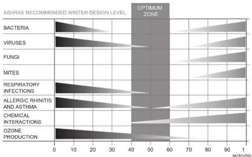
Maintaining Ideal Humidity
Dew points and relative humidity (RH) affect the way your body senses heat. Higher humidity levels cause the air to feel much hotter than the actual temperature. When maintained properly, your cooling equipment may not run as much because dehumidified air feels cooler.
Ideal humidity is defined by industry experts* as being between 40-60% on an average annual basis.
natural_image
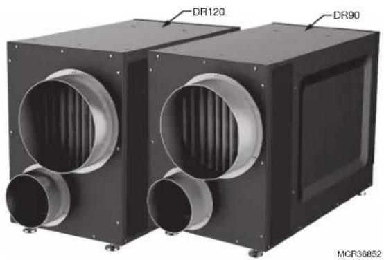
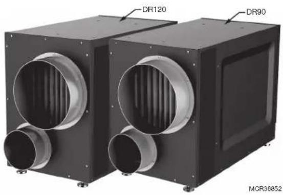
Two black industrial air ducts with ventilation ducts, labeled DR120 and DR90 (no text beyond labels)Capacity:
47 pints/day (60 °F [15.6 °C], 60 %RH)
65 pints/day (70 °F [21.1 °C], 60 %RH)
90 pints/day (80 °F [26.7 °C], 60 %RH)
When indoor humidity exceeds 60%, the home is more susceptible to mold and mildew growth. DR90A3000/DR120A3000 safeguards against excessive humidity in the home year-round.
*American Society of Heating, Refrigerating and Air Conditioning Engineers (ASHRAE).
bar
| Category | Value | | ---------------------------- | ----- | | BACTERIA | 40 | | VIRUSES | 40 | | FUNGI | 40 | | MITES | 40 | | RESPIRATORY INFECTIONS | 40 | | ALLERGIC RHINITIS AND ASTHMA | 40 | | CHEMICAL INTERACTIONS | 40 | | OZONE PRODUCTION | 40 |Control Options
The DR90A3000/DR120A3000 may be used with one of the following external controls:
natural_image
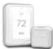
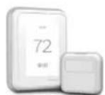
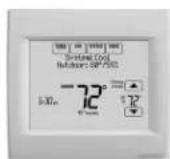
Two industrial control unit devices shown from different angles (no visible text or labels)T10 Pro Smart Thermostat (models begin with THX321WF)
- Controls heating/cooling and dehumidification.
- Advanced dehumidifier setting options to run system fan with dehumidifier or lock out dehumidifier if cooling is running.
Prestige IAQ Thermostat Kit
Prestige kit models numbers start with YTHX9421R
- Controls both heating/cooling and dehumidification.
- Wireless sensor for displaying outdoor temperature and humidity.
- Maintenance and service reminders.
• High definition color display.
• RedLINK® Wireless technology
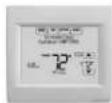
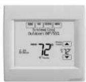
VisionPRO Smart or VisionPRO RedLINK® Thermostat
- Wi-Fi™ (TH8321WF1001) or RedLINK Wireless technology (TH8321R1001)
- Controls heating/cooling and ventilation.
• Display outdoor temperature and humidity. - Advanced dehumidifier setting options to run system fan with dehumidifier or lock out dehumidifier if cooling is running.
- Optional ventilation lockouts for high/low temp or humidity conditions. C7089R1013 wireless outdoor sensor for RedLINK model. Internet weather for Smart model.
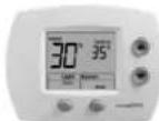
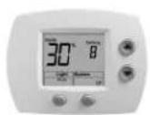
HumidiPRO Digital Control (H6062A1000)
- Manual dehumidification control
• Dehumidifier compressor protection - RH% and outdoor temperature calibration
- Adjustable high and low range stops (10-90%)
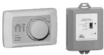
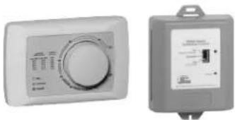
Manual Dehumidistat and Automatic Ventilation Controls
• H8908DSPST manual humidity control with intuitive comfort settings.
- Automatic W8150 ventilation control to ASHRAE standard, or for continuous operation.
DR90 Specifications
Install DR90A3000 according to National Electric Codes.
| Dry-Bulb Temp Intake Humidity Capacity (Pints/Day) | |
| 80°F (26.7°C) 60% RH 90 | |
| 70°F (21.1°C) 60% RH 65 | |
| 60°F (15.6°C) 60% RH 47 | |
| Home Size (square ft [m]) | Dehumidifier Capacity Required to Maintain Desired Indoor RH* | ||
| 60% RH Indoor (pints/day) | 50% RH Indoor (pints/day) | 40% RH Indoor (pints/day) | |
| 2080 (193.2) 49 | -54 55–58 71–78 | ||
| 2600 (241.5) 61 | -68 65–72 90–97 | ||
| 3120 (289.9) 75 | -82 79–86 95–110 | ||
* Based on extreme climates where outdoor humidity is 70-90% RH. For less extreme climates, larger homes can be adequately served with less capacity. Actual requirements may vary.
Dimensions in inches and (mm):
Product weight: 86 lbs.
Shipping weight: 95 lbs.
Shipping dimensions: 25.2" H × 19.3" W × 35.8" L
Media Filter: MERV 11, 14" H × 17.5" W × 1.75" L
Drain connection: 3/4" threaded female NPT connection.
Duct connections: 10" round inlet and outlet. 6" supply inlet. ABS plastic, compatible for connection to rigid or flexible ducting with sheet metal screws and/or tape.
Cabinet: 20 ga
Insulation: R value 1
Compressor: Rotary, 7.3 KBTU
Refrigerant: R-410A, 25 oz
Operating Temp Range (outside cabinet): 34°F to 135°F (1.1°C to 57.2°C)
Operating Humidity Range: 0-99% RH
Airflow versus external static pressure (0–1 in. [0 - 25.4 mm] water pressure) with collars attached
| 0 in. (0 mm) 320 CFM | |
| 0.2 in. (5 mm) 280 CFM | |
| 0.4 in. (10 mm) | 260 CFM |
| 0.6 in. (15.2 mm) | 215 CFM |
Input ratings
• Electrical input voltage: 120 VAC, 60 Hz nominal
- Input current: 5.3 A
Output ratings
• Power transformer to R/C terminals: 24 VAC, 0.85 A
• Energy Performance: 2.9 liters (6.1 pints) per kilowatt hour (KWH)
Standards and approval body requirements
• ETL Listed per UL 474 and CSA C22.2 No 92
• ENERGY STAR rated.
DR120 Specifications
Install DR120A3000 according to National Electric Codes.
Dry-Bulb Temp Intake Humidity Capacity (Pints/Day)
80^(26.7^) 60% RH 120
70°F (21.1°C) 60% RH 88
60°F (15.6°C) 60% RH 63
Home Size Dehumidifier Capacity Required to Maintain Desired Indoor RH*
| (square ft [m]) | 60% RH Indoor(pints/day) | 50% RH Indoor(pints/day) | 40% RH Indoor(pints/day) |
2080 (193.2) 49-54 55-58 71-78
2600 (241.5) 61-68 65-72 90-97
3120 (289.9) 75-82 79-86 95-110
* Based on extreme climates where outdoor humidity is 70-90% RH. For less extreme climates, larger homes can be adequately served with less capacity. Actual requirements may vary.
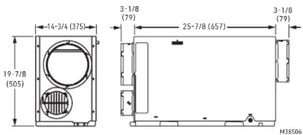
Dimensions in inches and (mm):
| 3-1/8(79) | 3-1/8(79) | ||
| 14-3/4 (375) | 25-7/8 (657) |
20-1/2 (521)
M38505
Product weight: 95 lbs.
Shipping weight: 104 lbs.
Shipping dimensions: 26" H × 19.3" W × 35.8" L
Media Filter: MERV 11, 14" H × 17.5" W × 1.75" L
Drain connection: 3/4" threaded female NPT connection.
Duct connections: 10" round inlet and outlet. 6" supply inlet. ABS plastic, compatible for connection to rigid or flexible ducting with sheet metal screws and/or tape.
Cabinet: 20 ga
Insulation: R value 1
Compressor: Rotary, 9.4 KBTU
Refrigerant: R-410A, 30 oz
Operating Temp Range (outside cabinet):
34°F to 135°F (1.1°C to 57.2°C)
Operating Humidity Range: 0-99% RH
Airflow versus external static pressure (0–1 in. [0 - 25.4 mm] water pressure) with collars attached
0 in. (0 mm) 400 CFM
0.2 in. (5 mm) 345 CFM
0.4 in. (10 mm) 295 CFM
0.6 in. (15.2 mm) 250 CFM
Input ratings
• Electrical input voltage: 120 VAC, 60 Hz nominal
- Input current: 7.3 A
Output ratings
• Power transformer to R/C terminals: 24 VAC, 0.85 A
• Energy Performance: 2.9 liters (6.1 pints) per kilowatt hour (KWH)
Standards and approval body requirements
• ETL Listed per UL 474 and CSA C22.2 No 92
- ENERGY STAR rated.
Install to Fit Your Application
Flex duct is recommended in connecting to the DR90A3000/DR120A3000 collars to reduce vibration noise.
natural_image
Two black industrial air ducts with ventilation ducts, labeled DR120 and DR90 (no text or symbols on the devices themselves)Duct Sizing: Use minimum 10" diameter round for duct lengths up to 25' Minimum 12" required for lengths longer than 25' Duct branches from the main inlet/exhaust should be minimum 10" round for 2-3 branches, and 12" round or larger for 4 branches or more.
For the optional fresh air ventilator port, use 6" round, insulated duct for lengths up to 50' Use 8" round duct for more than 50' of if more than 100 CFM is required.
Isolated Areas: Effective dehumidification may require ducting to isolated or stagnant air flow areas.
Electrical requirements:
115 VAC outlet. Ground fault interrupter (GFI) recommended.
Dedicated Return to Dedicated Supply
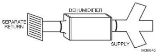
flowchart
graph LR
    A["SEPARATE RETURN"] --> B["DEHUMIDIFIER"]
    B --> C["SUPPLY"]
    C --> D["M36646"]
Ideal when...
- The dehumidifier will not be ducted to a forced air HVAC system.

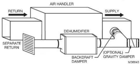
Dedicated Return to Main Supply
flowchart
graph LR
    A["AIR HANDLER"] -->|RETURN| B["SEPARATE RETURN"]
    A -->|SUPPLY| C["DEHUMIDIFIER"]
    C --> D["BACKDRAFT DAMPER"]
    D --> E["(OPTIONAL) GRAVITY DAMPER M36843"]
Ideal when...
- Access to dedicated central return for dehumidifier is available.
- Combined with A/C operation, requires backdraft damper on the exhaust port to minimize backdraft when dehumidifier is not on but A/C is.
- (optional) Duct humidifier supply with 20% open gravity damper to provide dry air to a specific area
Install to Fit Your Application (continued)
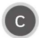
Main Return to Main Supply
flowchart
graph LR
    A["AIR HANDLER"] --> B["DEHUMIDIFIER"]
    B --> C["BACKDRAFT DAMPER M36844"]
    D["RETURN"] --> A
    E["SUPPLY"] --> F["Supply"]
Ideal when...
- When IAQ thermostat is used and configured for "Dehumidifier Not Allowed when Cool is Running".
- Requires damper on the exhaust port to minimize backdraft when DR90A3000/DR120A3000 is not on but A/C is.
- Access to a dedicated central return is not possible.
- System fan should run with dehumidifier for best results.

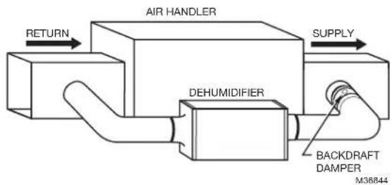
Main Return to Main Return
flowchart
graph LR
    A["Return"] --> B["AIR HANDLER"]
    B --> C["SUPPLY"]
    D["DEHUMIDIFIER"] --> B
    style A fill:#f9f,stroke:#333
    style B fill:#ccf,stroke:#333
    style C fill:#cfc,stroke:#333
    style D fill:#fcc,stroke:#333
Ideal when...
- Running DR90A3000/DR120A3000 with A/C operation.
- Minimizing discharge air temperature (DAT) increase is preferred.
- Access to a dedicated return is not possible.
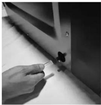
Plumbing
natural_image
Close-up of a hand holding a pen, applying material to a small object on a surface (no visible text or symbols)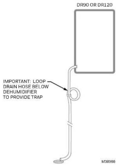
Attach 3/4" male NPT PCV drain nozzle (use teflon tape if needed). Do not over-tighten.
Connect 1/2" drain tube to male connection drain outlet. Secure drain tube to connector with hose clamp.
Run drain hose continuously downhill to an approved drain or condensate pump.
The drain line must include a water trap to prevent air from entering or exiting the dehumidifier.
NOTE: It is important that the DR90/DR120 is leveled for drain line to work properly.
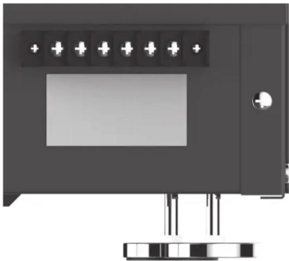
Terminal Description

CAUTION: Low voltage hazard.
Can cause equipment damage.
Disconnect HVAC equipment before beginning installation.
natural_image
Front view of a black electronic device with indicator lights and a display screen (no visible text or symbols)NOTE: The outer screws on the terminal block secure the block to the chassis. They are not used for wiring.
A wiring terminal block is located on the side panel of the dehumidifier unit.
The six terminals for the terminal block (reading from left to right in the photo) are:
FLOAT: External low voltage float switch or water sensor (two terminals). Use normally closed switch.
DHUM: Compressor and fan operation for dehumidification
R: 24V HOT output
FAN: Fan activation only for ventilation
C: 24V Common output
External 24V devices can be powered from R and C terminals (20VA max.).
Wiring
Wire the DR90A3000/DR120A3000 according to the diagram that applies to your desired operation.
Follow this diagram if using the Prestige thermostat.
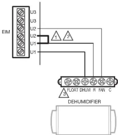
1 IN THIS DIAGRAM, U1 CONTROLS THE DR90/DR120 FOR DEHUM AND U2 CONTROLS THE DR90/DR120 FOR VENTILATION.
2 INSTALL A JUMPER ON EIM AS SHOWN ONLY WHEN USING THE DR90/DR120 FOR VENTILATION IN ADDITION TO DEHUMIDIFICATION.
3 IF A FLOAT SWITCH IS NOT USED, THEN JUMPER THE FLOAT TERMINALS M3841BA
Wiring (continued)
FOLLOW THIS DIAGRAM IF USING THE HUMIDIPRO DIGITAL HUMIDITY CONTROLLER.
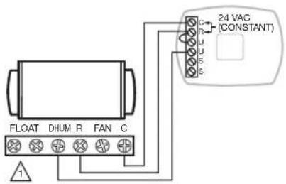
IF A FLOAT SWITCH IS NOT USED, THEN JUMPER THE FLOAT TERMINALS.
M37492A
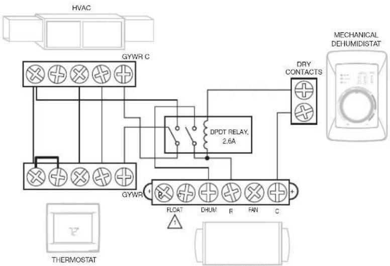
FOLLOW THIS DIAGRAM FOR DUCTED OPERATION WITH AN EXTERNAL HUMIDITY CONTROL.
flowchart
graph TD
    A["HVAC"] --> B["GYWR C"]
    B --> C["DPDT RELAY, 2.6A"]
    C --> D["DRY CONTACTS"]
    D --> E["MECHANICAL DEHUMIDISTAT"]
    F["THERMOSTAT"] --> G["GYWR"]
    G --> H["FLOAT"]
    G --> I["DHUM"]
    G --> J["R"]
    G --> K["FAN"]
    G --> L["C"]
    M["Ground"] --> N["Ground"]
A FLOAT SWITCH IS NOT USED, THEN JUMPER THE FLOAT TERMINALS.
M36854B
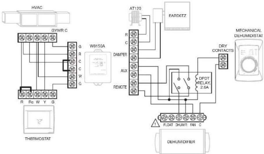
FOLLOW THIS DIAGRAM FOR DUCTED OPERATION WITH EXTERNAL HUMIDITY AND VENTILATION CONTROL.
flowchart
graph TD
    A["HVAC"] --> B["GYWR C"]
    B --> C["W8150A"]
    C --> D["AT120"]
    D --> E["EARD6TZ"]
    E --> F["DRY CONTACTS"]
    F --> G["DEHUMIDIFIER"]
    G --> H["FLOAT DHUMR FAN C"]
    H --> I["DPDT RELAY, 2.6A"]
    I --> J["AUX"]
    J --> K["REMOTE"]
    K --> L["DAMPER"]
    L --> M["R"]
    M --> N["C"]
    N --> O["G"]
    O --> P["Rc W Y G"]
    P --> Q["THERMOSTAT"]
IF A FLOAT SWITCH IS NOT USED, THEN JUMPER THE FLOAT TERMINALS.
M36855A
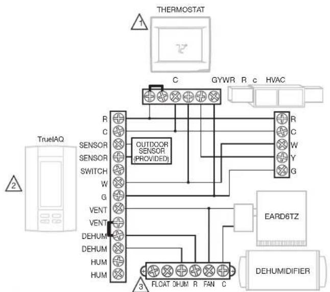
Wiring (continued)
Follow this diagram if using DR90A3000/DR120A3000 with a powered dehumidistat such as the DG115 IAQ control (DG115EZIQ).
flowchart
graph TD
    A["Thermostat"] --> B["C"]
    B --> C["GYWR"]
    B --> D["R"]
    B --> E["c"]
    B --> F["HVAC"]
    G["TrueIAQ"] --> H["R"]
    G --> I["C"]
    G --> J["SENSOR"]
    G --> K["SENSOR"]
    G --> L["SWITCH"]
    G --> M["W"]
    G --> N["G"]
    G --> O["VENT"]
    G --> P["VENT"]
    G --> Q["DEHUM"]
    G --> R["DEHUM"]
    G --> S["HUM"]
    G --> T["HUM"]
    U["Outdoor Sensor (PROVIDED)"] --> V["3"]
    W["EARD6TZ"] --> X["FLOAT DHUM R FAN C"]
    Y["DEHUMIDIFIER"] --> Z["3"]
1 IF A THERMOSTAT OTHER THAN A TH5110, TH5220, TH5320, TH6110, TH6220, TH6320, TH8110, TH8320, OR TH8321 IS USED, A RELAY MAY BE REQUIRED TO ISOLATE THE G WIRE.
2 PROGRAM ISU SETTING 60 TO 0 TO FORCE SYSTEM FAN ON WITH DEHUMIDIFICATION CALL.
3 IF A FLOAT SWITCH IS NOT USED, THEN JUMPER THE FLOAT TERMINALS. M38856A
Checkout
Apply power to DR90A3000/DR120A3000. Turn the humidity control to a low RH% level to initiate a dehumidification call. Confirm that the DR90A3000/DR120A3000 compressor and fan turn on. The furnace blower will also turn on to circulate air. This will take up to two minutes. Be sure to turn the control to the desired RH% or to Off when checkout is complete.
If using for ventilation, initiate a call for ventilation. Confirm that the DR90A3000/DR120A3000 fan turned on, but that the compressor remained off.
Cleaning
On an annual basis, perform the following maintenance requirement to ensure the dehumidifier runs at peak efficiency.

Unplug DR90A3000/ DR120A3000 before beginning service. Remove the magnetic filter door.
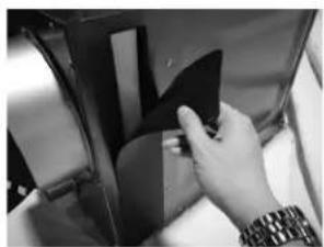
natural_image
Close-up of a hand inserting a black plastic component into a car seat (no visible text or symbols)
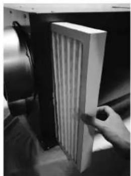
Remove filter and replace with new filter.
natural_image
Hand placing a white panel with ribbed structure inside a device (no visible text or symbols)
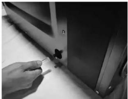
Check the drain connection and drain line to ensure it is clear of debris and sludge. Ensure all hose connections are secure once maintenance of the drain lines is complete.
natural_image
Close-up of a hand holding a small object near a window (no visible text or symbols)
When service is complete, initiate a call for dehumidification and check that the compressor and fan activate. If your thermostat has maintenance reminders, reset those.
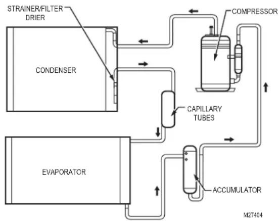
Technical Description
DR90A3000/DR120A3000 uses a refrigeration system similar to an air conditioner to remove heat and moisture from incoming air and add heat to the air that is discharged. Hot, high-pressure refrigerant gas is routed from the compressor to the condenser coil. The refrigerant is cooled and condensed by giving up its heat to the air that is about to be discharged from the unit. The refrigerant liquid then passes through a filter drier and capillary tubing which causes the refrigerant pressure and temperature to drop. It next enters the evaporator coil where it absorbs heat from the incoming air and evaporates. The evaporator operates in a flooded condition, which means that all the evaporator tubes contain liquid refrigerant during normal operation. A flooded evaporator should maintain nearly constant pressure and temperature across the entire coil, from inlet to outlet.
flowchart
graph TD
    A["CONDenser"] --> B["STRAINER/FILTER DRIER"]
    B --> C["COMPRESSOR"]
    C --> D["CAPILLARY TUBES"]
    D --> E["ACCUMULATOR"]
    E --> F["EVAPORATOR"]
    F --> G["M27404"]
Troubleshooting
Troubleshooting videos are available on the Resideo Pro YouTube channel playlist.

CAUTION: Servicing the DR65A3000 with its high pressure refrigerant system and high voltage circuitry presents a health hazard which could result in death, serious bodily injury, and/or property damage. Service should only be performed by a qualified service technician.
| Problem Recommended Troubleshooting Steps | |
| No dehumidification. Neither fan nor compressor run and the ventilation timer is OFF. | Unit unplugged or no power to outlet.Humidity control set too high or defective.Loose connection in internal or control wiring.Defective compressor relay.Defective control transformer.Optional Condensate Pump Safety Switch open. |
| No dehumidification. Compressor does not run but fan runs when there is a call for dehumidification and the ventilation control is OFF. | Defective compressor run capacitor.Bad connection in compressor circuit.Defective compressor overload.Defective compressor.Defrost thermostat open.Optional Condensate Pump Safety Switch open. |
| Fan runs when there is a call for dehumidification and the ventilation control is OFF, but the compressor cycles on and off too frequently. | Low ambient temperature and/or humidity causing unit to cycle through defrost mode.Defective compressor overload.Defective compressor.Defrost thermostat defective.Dirty air filter(s) or airflow restricted.Low refrigerant charge, causing defrost control to cycle.Bad connection in compressor circuit. Fan does not run with fan switch in either position. |
Troubleshooting (continued)
| Problem Recommended Troubleshooting Steps | |
| Fan does not run with ventilation activated.Compressor runs briefly but cycles on & off with humidity control turned to ON. | 1. Loose connection in fan circuit.2. Obstruction prevents fan rotation.3. Defective fan.4. Defective fan relay.5. Defective fan capacitor. |
| Evaporator coil frosted continuously, low de-humidifying capacity. | 1. Defrost thermostat loose or defective.2. Low refrigerant charge.3. Dirty air filter(s) or airflow restricted. |
| Unit not providing ventilation. | 1. Check control wire connections (check connections at fresh air damper also).2. Defective fresh air damper.3. Dirty air intake. Clean outside intake hood. |
| Unit removes some water, but not as much as expected. | 1. Air temperature and/or humidity have dropped.2. Humidity meter and or thermometer used are out of calibration.3. Unit has entered defrost cycle.4. Dirty air filter.5. Defective defrost thermostat.6. Low refrigerant charge.7. Air leak such as loose cover or ducting leaks.8. Defective compressor.9. Restrictive ducting.10. Optional Condensate Pump Safety Switch open. |
| Unit Test to determine problem: | 1. Detach field control wiring connections from main unit.2. Connect the R and FAN contacts from the main unit together; only the impeller fan should run. Disconnect the wires.3. Connect the R and DHUM contacts from the main unit together; the compressor and impeller fan should run.4. If these tests work, the main unit is working properly. You should check the control panel and field control wiring for problems next.5. Remove the control panel from the mounting box and detach it from the field installed control wiring. Connect the blue, yellow, and green wires from the control panel directly to the corresponding colored pigtails on the main unit.Leave the violet, white, and red wires disconnected!6. Turn on the humidity control. The compressor and impeller fan should run.7. If these tests work, the problem is most likely in the field control wiring. |
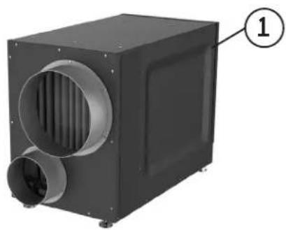
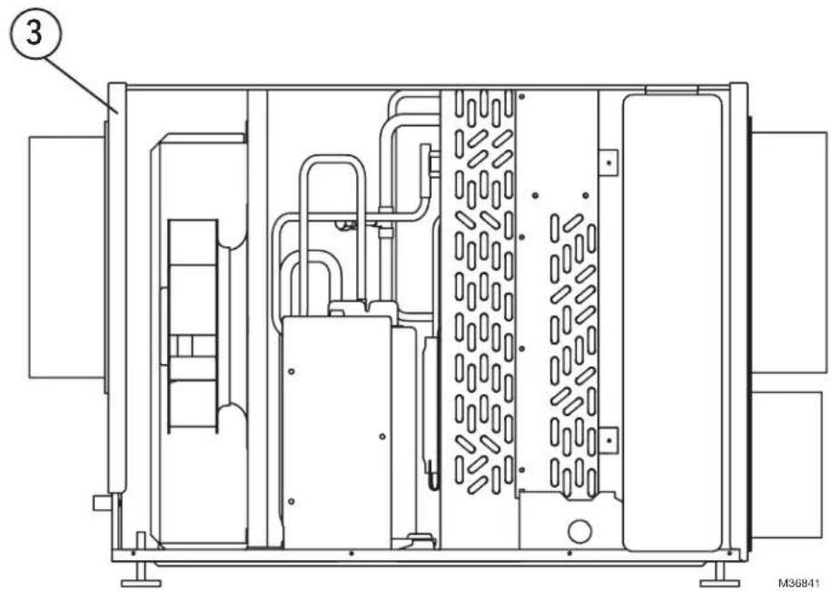
DR90/DR120 Parts List
| Figure Reference Base and Accessory Parts Part Number | |
| 1 Dehumidifier DR90A3000/U | |
| 1 Dehumidifier DR120A3000 | |
| 2 Motorized Ventilation Damper EARD6TZ | |
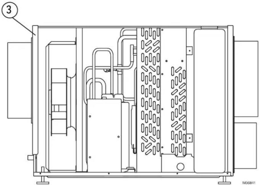
| 3 Filter 50070171-002 | |
| 4 Replaceable Fuse T2.5A L 250V (NOT SOLD BY RESIDEO) | |
natural_image
Exterior view of a black industrial air duct or fan unit with ventilation ducts and a labeled component (1), no visible text or symbols beyond the label.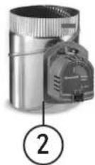
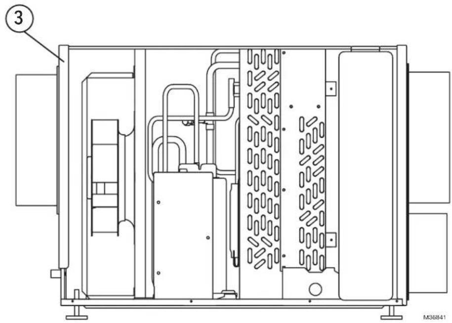
natural_image
Technical line drawing of an industrial machine interior with no visible text or symbolsFor reference only.
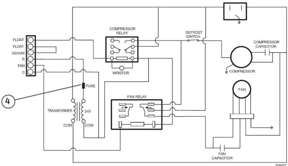
flowchart
graph TD
    A["FLOAT"] --> B["TRANSFORMER"]
    C["DEHUM"] --> B
    D["R"] --> B
    E["FAN"] --> B
    F["C"] --> B
    B --> G["FUSE"]
    G --> H["24V"]
    H --> I["COM"]
    I --> J["COM"]
    J --> K["COMPRESSOR RELAY"]
    K --> L["WRISTOR"]
    L --> M["DEFROST SWITCH"]
    M --> N["COMPRESSOR CAPACITOR"]
    N --> O["FAN"]
    O --> P["FAN CAPACITOR"]
    P --> Q["FAN RELAY"]
    Q --> R["FAN"]
    R --> S["COMPRESSOR"]
    S --> T["CONCLOSURE Capacitor"]
    T --> U["CONCLOSURE Capacitor"]
    U --> V["CONCLOSURE Capacitor"]
    V --> W["CONCLOSURE Capacitor"]
    W --> X["CONCLOSURE Capacitor"]
    X --> Y["CONCLOSURE Capacitor"]
    Y --> Z["CONCLOSURE Capacitor"]
    Z --> AA["CONCLOSURE Capacitor"]
    AA --> AB["CONCLOSURE Capacitor"]
    AB --> AC["CONCLOSURE Capacitor"]
    AC --> AD["CONCLOSURE Capacitor"]
    AD --> AE["CONCLOSURE Capacitor"]
The product should not be disposed of with other household waste. Check for the nearest authorized collection centers or authorized recyclers. The correct disposal of end-of-life equipment will help prevent potential negative consequences for the environment and human health.
5-Year Limited Warranty
Resideo warrants this product to be free from defects in workmanship or materials, under normal use and service, for a period of five (5) years from the date of first purchase by the original purchaser. If at any time during the warranty period the product is determined to be defective due to workmanship or materials, Resideo shall repair or replace it (at Resideo's option).
If the product is defective,
(i) return it, with a bill of sale or other dated proof of purchase, to the place from which you purchased it; or (ii) call Resideo Customer Care at 1-800-468-1502. Customer Care will make the determination whether the product should be returned to the following address: Resideo Return Goods, 1985 Douglas Dr. N., Golden Valley, MN 55422, or whether a replacement product can be sent to you.
This warranty does not cover removal or reinstallation costs. This warranty shall not apply if it is shown by Resideo that the defect was caused by damage which occurred while the product was in the possession of a consumer.
Resideo's sole responsibility shall be to repair or replace the product within the terms stated above. RESIDEO SHALL NOT BE LIABLE FOR ANY LOSS OR DAMAGE OF ANY KIND, INCLUDING ANY INCIDENTAL OR CONSEQUENTIAL DAMAGES RESULTING, DIRECTLY OR INDIRECTLY, FROM ANY BREACH OF ANY WARRANTY, EXPRESS OR IMPLIED, OR ANY OTHER FAILURE OF THIS PRODUCT.
Some states do not allow the exclusion or limitation of incidental or consequential damages, so this limitation may not apply to you.
THIS WARRANTY IS THE ONLY EXPRESS WARRANTY RESIDEO MAKES ON THIS PRODUCT. THE DURATION OF ANY IMPLIED WARRANTIES, INCLUDING THE WARRANTIES OF MERCHANTABILITY AND FITNESS FOR A PARTICULAR PURPOSE, IS HEREBY LIMITED TO THE FIVE YEAR DURATION OF THIS WARRANTY. Some states do not allow limitations on how long an implied warranty lasts, so the above limitation may not apply to you.
This warranty gives you specific legal rights, and you may have other rights which vary from state to state. If you have any questions concerning this warranty, please write Resideo Customer Care, 1985 Douglas Dr, Golden Valley, MN 55422 or call 1-800-468-1502.

resideo
www.resideo.com
Resideo Technologies Inc.
1985 Douglas Drive North, Golden Valley, MN 55422
1-800-468-1502
33-00298EFS-11 M.S. Rev. 05-22 | Printed in United States
© 2022 Resideo Technologies, Inc. All rights reserved. The Honeywell Home trademark is used under license from Honeywell International, Inc.
This product is manufactured by Resideo Technologies, Inc. and its affiliates.
Description technique 12
Dépannage 12
natural_image
Two black industrial air ducts with ventilation ducts, labeled DR120 and DR90 (no text or symbols on the structures themselves)natural_image
Two industrial control devices with circular gauges and indicator lights (no visible text or symbols)* RH = HUMIDITÉ RELATIVE
natural_image
Two black industrial air ducts with ventilation ducts, labeled DR120 and DR90 (no additional text or symbols visible)natural_image
Close-up of a hand holding a small object with a butterfly-shaped object attached to a wooden table (no visible text or symbols)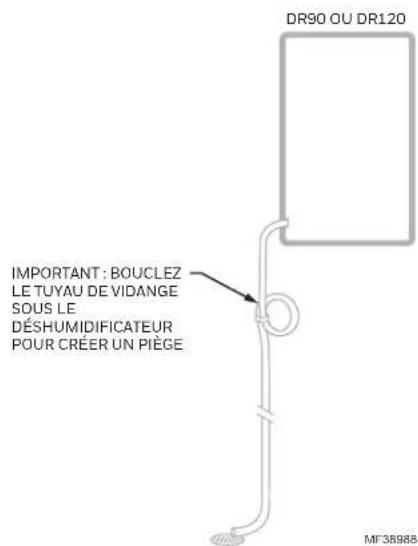
natural_image
Pure electrical circuit lines without any symbolsnatural_image
Close-up of a hand inserting a dark object into a circular component (no visible text or symbols)
natural_image
Close-up of a hand inserting a white panel into a device (no visible text or symbols)
natural_image
Close-up of a hand holding a small object near a cabinet (no visible text or symbols)
Description technique
natural_image
Exterior view of a black industrial air conditioning unit with ventilation ducts and a labeled component (1), no visible text or symbols beyond the label.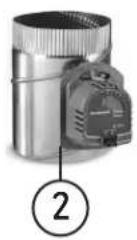
Resideo Technologies Inc.
1985 Douglas Drive North, Golden Valley, MN 55422
1-800-468-1502
© 2022 Resideo Technologies, Inc. All rights reserved. The Honeywell Home trademark is used under license from Honeywell International, Inc. This product is manufactured by Resideo Technologies, Inc. and its affiliates.
natural_image
Two black industrial air ducts with ventilation ducts, labeled DR120 and DR90 (no additional text or symbols visible)Capacidad :
47 pintas/día (60 °F [15,6 °C], 60% de HR) 65 pintas/día (70 °F [21,1 °C], 60% de HR) 90 pintas/día (80 °F [26,7 °C], 60% de HR)
natural_image
Two industrial control panels with circular gauges and indicator lights (no visible text or symbols)Termostato inteligente T10 Pro (los modelos comienzan con THX321WF)
natural_image
Two black industrial air ducts with ventilation ducts, labeled DR120 and DR90 (no text beyond labels)natural_image
Close-up of a hand holding a small object near a wall, with no visible text or symbols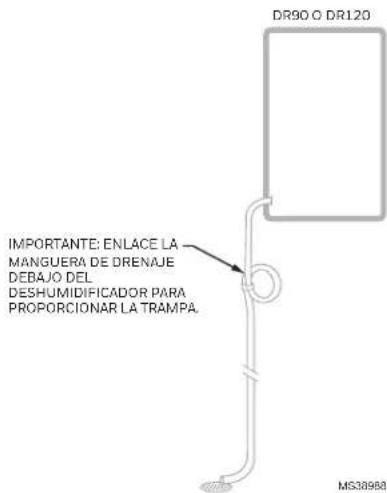
natural_image
Pure electrical circuit lines without any symbolsnatural_image
Close-up of a hand adjusting a dark object on a vehicle (no visible text or symbols)
natural_image
Hand inserting a vertical panel into a rack, no visible text or symbols
natural_image
Close-up of a hand holding a small object near a cabinet (no visible text or symbols)Descripción técnica
natural_image
Exterior view of a black industrial air duct or fan unit with ventilation ducts and a labeled component (1), no visible text or symbols beyond the label.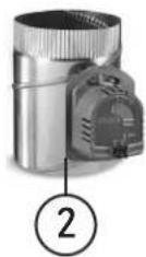
natural_image
Technical line drawing of an industrial machine or enclosure with internal components and no visible text or symbolsResideo Technologies Inc.
1985 Douglas Drive North, Golden Valley, MN 55422
1-800-468-1502
© 2022 Resideo Technologies, Inc. All rights reserved. The Honeywell Home trademark is used under license from Honeywell International, Inc.
This product is manufactured by Resideo Technologies, Inc. and its affiliates.