
TravellerMan 3 - Receiver MEGASAT - Free user manual and instructions
Find the device manual for free TravellerMan 3 MEGASAT in PDF.
| Product type | Satellite receiver (flat antenna with control unit) |
| Brand | Megasat |
| Model | TravellerMan 3 |
| Antenna dimensions | 525 x 145 x 480 mm (L/H/D) |
| Antenna weight | 7 kg |
| Control unit dimensions | 195 x 30 x 150 mm (L/H/D) |
| Control unit weight | 360 g |
| Power supply | 12 V DC / 5 A (via battery or external power supply) |
| Antenna type | Flat antenna |
| Frequency band | Ku band (10.7 GHz to 12.75 GHz) |
| LNB gain | 33 dBi |
| Reception performance | 49 dBW |
| Polarization | Vertical / Horizontal |
| Tilt angle | 0° to 90° |
| Search angle | 365° |
| Temperature range | -25 °C to +70 °C |
| Number of users | 2 (two televisions possible) |
| Main functions | Automatic satellite search, control via control unit or Bluetooth mobile app, firmware update, automatic retraction (contact option), satellite selection |
| Maintenance and cleaning | Clean the housing with a soft, dry cloth; avoid dirt on the antenna which can impair reception |
| Safety | Do not expose the control unit to water; use a 7 A fuse on the power cable; do not exceed 12 V DC |
| Spare parts and repairability | Coaxial cables supplied (1 m and 2x10 m), roof feed-through, optional mobile kit (ref. 1201000); firmware update possible via the app |
| General information | Compliant with directives 2014/30/EU, 2014/35/EU, 2014/53/EU; product registration possible at www.megasat.tv |
Frequently Asked Questions - TravellerMan 3 MEGASAT
User questions about TravellerMan 3 MEGASAT
0 question about this device. Answer the ones you know or ask your own.
Ask a new question about this device
Download the instructions for your Receiver in PDF format for free! Find your manual TravellerMan 3 - MEGASAT and take your electronic device back in hand. On this page are published all the documents necessary for the use of your device. TravellerMan 3 by MEGASAT.
USER MANUAL TravellerMan 3 MEGASAT
Traveller-Man 3
Bedienungsanleitung
WICHTIG!!!
Art-Nr.: 1201000
1. Einführung
1.3 Systemkomponenten

ACHTUNG!
Antenneneinheit
2. Installation

2. Installation
Reading data from server...
Latest version already updated
New software available


HOT Hotbird (13° Ost)
HIS Hispasat (30° West)
E9E Eutelsat 9 B (9° Ost)
E5W Eutelsat 5 West (5° West)
TUR Türksat (42° Ost)
THO Thor (0,8° West)
Hinweis:
Hinweis:
Traveller-Man 3
user manual
IMPORTANT!!!
Please carry out a firmware update before using the antenna for the first time, with the Megasat app, perform a firmware update!
1. Introduction
1.1 Safety Information 03
1.2 Delivery 03
1.3 System components....04
2. Installation
2.1 Setting the Antenna to Installation Mode 05
2.2 Installation on the roof 06
2.3 Gluing instructions....07
2.4 Indoor installation....08
2.5 Connection of the components 09
2.6 The control unit....10
2.7 Satellite transmission....11
3. Satellite search with the control unit
3.1 Designation of the respective LEDs and keys....12
3.2 Satellite search.... 13
4. Mobile app for controlling the antenna
4.1 Connecting the control unit to the mobile device 14
4.2 Firmware update of the antenna....16
4.3 Change satellite 17
4.4 Disconnect Bluetooth connection....17
-
Troubleshooting....18
-
Footprint....19
-
Mounting dimensions....20
-
Specifications....21
1. Introduction
1.1 Safety Information

Please read the user manual carefully before you start the installation. If you have already installed similar products, the procedure may not be the same as for this product.
- Improper handling can cause serious damage to this device. Those responsible may also be held responsible for any resulting further damage to the equipment.
- Please check the correct operating voltage of your power supply before commissioning. Please refer to the specifications in this user manual for the operating voltage of the device.
- The control unit must not be exposed to dripping water, splashing water or other liquids.
- Do not let children play with foils or other packaging materials, there is a danger of suffocation.
1.2 Delivery
■ 1x Traveller-Man 3
■ 1x Control unit incl. powercable
■ 1x Coax cable (1 m)
■ 1x Coax cable (10 m)
■ 1x Roof lead-through
■ 1x User manual
Optional accessories:
Mobile Kit 3
for mobile use

Art-No.: 1201000
1. Introduction
1.3 System components
Open the carton and remove the control unit, connection cables and packing material. Lift the antenna straight up out of the box. Never turn the system upside down!


WARNING!
Never touch the antenna directly to the dish when lifting it out of the box. Lift the antenna by the base plate.

Antenna unit
The high-performance antenna, the elevation angle of 0-90° and the auto-skew function enable the best possible reception in the most important holiday destinations in Europe.
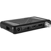
Control unit
The control unit is used for satellite selection and control. It is connected between antenna and TV (receiver) and supplies the antenna with power. After successful alignment the device can be switched off.
Note:
The Traveller-Man 3 has an additional connection for a second TV or receiver. For the correct connection of the components, please refer to the connection diagram in this operating manual.
2. Installation

As a matter of principle, we recommend having the installation carried out by your specialist dealer or a specialist workshop! Please also note that the vehicle height changes accordingly due to the antenna! Please strictly adhere to the individual points of the installation instructions!
General information
Provide a suitable workplace, a garage/hall is better than an outdoor place. The ambient temperature for installation must be between +5°C and max. +25°C. Do not work directly in the sun. Observe the work regulations when handling chemical products. Ensure the necessary work hygiene.
2.1 Setting the Antenna to Installation Mode
To remove the mounting plate from the antenna, we recommend to set the antenna into installation mode to be able to loosen the four Allen screws more easily. To do this, you must first connect the antenna and the control unit provisionally.
- Connect the supplied antenna cable (10 m) to the antenna and the control unit.
- Connect the supplied power cable to a power source (12 V, min. 5 A) and the control unit.
-
Switch the control unit on at the standby button.
-
The antenna now points upwards. Once the antenna is upright, disconnect the power supply from the control unit.
-
Loosen the four Allen screws to lift the antenna unit from the mounting plate.
-
Now remove all connection cables to start the installation.

2. Installation
2.2 Installation on the roof
- Make sure that the roof of your vehicle is sufficiently stable. If the roof stability is insufficient or doubtful, attach an approx. 2 mm thick sheet metal plate measuring approx. 100 x 100 cm to the outer skin of the roof. Please ask your vehicle manufacturer for more information.

Important:
The antenna must point with the motor unit in driving direction!
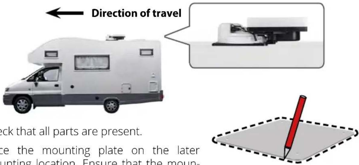
- Check that all parts are present.
- Place the mounting plate on the later mounting location. Ensure that the moun-
ting surface is level and that no roof structures are in the way. It is essential to observe the mounting dimensions in these instructions. The minimum distance to an air conditioner should be 30 cm.
- Clean the mounting surface with a suitable cleaner and a fleece cloth to remove dirt and impurities. Then mark the base plate of the antenna with a pen.
- Slightly roughen the drawn surfaces and feet with sandpaper (120 grain) and clean the surface again with the cleaner and allow the cleaner to flash off for about 10 minutes. WARNING: Do not touch the surfaces afterwards.
- Mount the roof lead-through (preferably in the slipstream behind the antenna) on the vehicle roof. Make sure that the penetration of water and moisture (e.g. rain or splash water) into the drill hole is avoided. Make sure that the cables are not bent too much to avoid signal loss and damage to the cable (smallest bending radius max. 5-7 cm).
2. Installation
2.3 Gluing instructions
-
Prepare the adhesive for mounting.
-
Now apply the adhesive to the underside of the antenna base in serpentine lines so that the adhesive cures well all the way inside.
-
Now immediately (within 5 minutes after applying the adhesive) place the antenna on the marked field. Press the foot lightly and evenly and fix the antenna so that it does not slip, e.g. with adhesive tape. There must still be at least 2 mm of adhesive between the antenna foot and the surface after pressing on. The adhesive is cured after max. 48 hours at +18° C and a relative humidity of 50% . If there is a low humidity during the installation period, spray some water into the air around the antenna after the adhesive has been applied.
-
Remove any leaked adhesive mass immediately with a spatula or similar and clean the soiled surfaces with the cleaner and a fleece cloth.
-
After the complete assembly and hardening of the adhesive, a silicone joint can be drawn around the mounting plate.
-
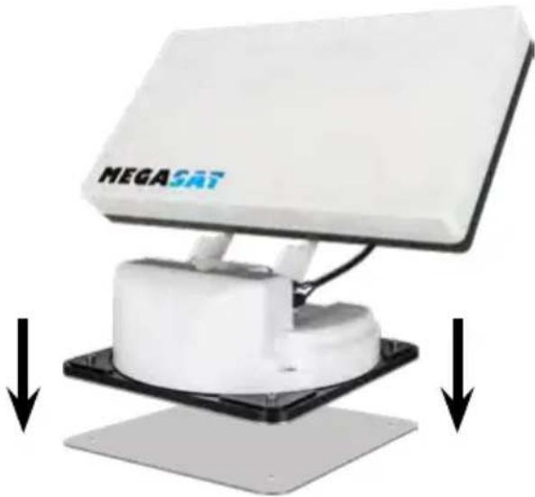
Then place the antenna on the mounting plate and fasten it again with the four Allen screws.

2. Installation
2.3 Indoor installation
- The coax cable is laid inside the vehicle.
- When choosing the location for the control unit and the satellite receiver, make sure that both devices are in a dry and protected place.
- Do not place the control unit and satellite receiver near heat sources and ensure sufficient ventilation.
-
The basic connection options for the antenna system are shown below:
-
Connect the power supply (red-black cable) for the control unit to your vehicle's battery via a fuse (7 amps) to prevent cable fire in the event of a short circuit. The yellow cable is connected to the ignition plus of the vehicle and is also protected by a 7 amp fuse (This cable only needs to be connected if the antenna is to retract automatically when the engine is started). The remaining black cable is connected to the corresponding negative pole of the ignition system (ground).
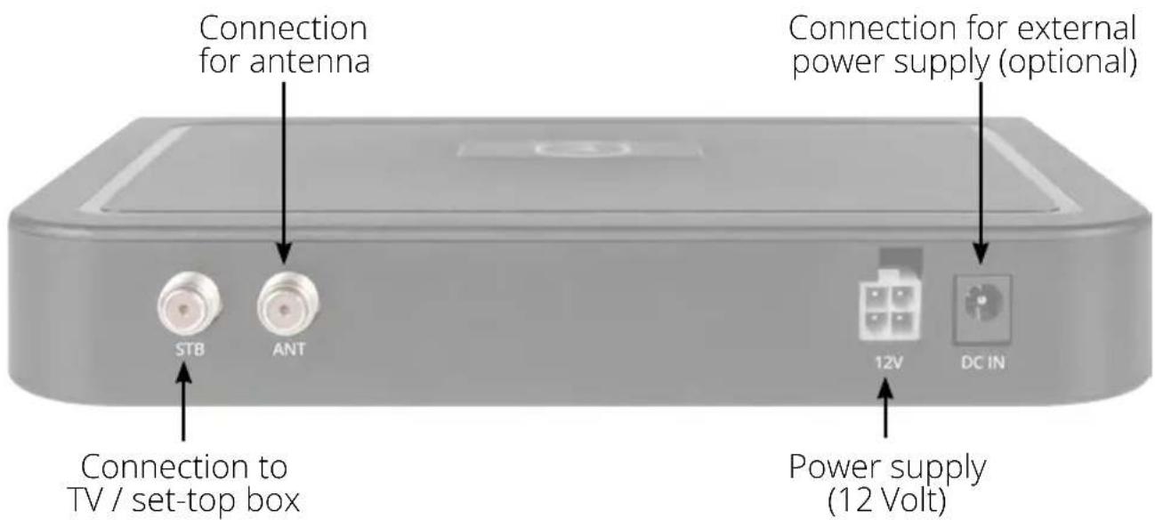
- Connect the coax cable from the antenna to the control unit (10 m coax cable with F-plug in „ANTENNA“)
- Connect the control unit to the TV or satellite receiver (1 m coaxial cable with F-plug from „RECEIVER“ to the satellite receiver)
Note:
If you want to operate two TV sets, connect a second coaxial cable from the antenna directly to the second TV or satellite receiver.
2. Installation
2.5 Connection of the components
Ignition plus
The antenna automatically moves to the retracted position as soon as the ignition key is turned. This function is only guaranteed if the control unit is switched on and cable 4 is connected to the negative pole and cable 5 to the ignition plus of the vehicle.
Power supply
DC 12 V via battery (positive pole permanent supply RED) or optional 230 V/12 V DC power supply (no chargers). Make sure that a current of at least 5 amperes is guaranteed.
① Coax cable 10 m
② Coax cable 1 m
③ — Positive pole
④ — Negative pole
⑤ Ignition plus
![graph TD A["Control unit"] -->|①| B["MEGA/BoxANT"] B -->|②| C["Television 2 Television 1"] C -->|③ (+) (-)| D["ReceiverSTB"] D -->|④ (-) (+)| E["Second coaxial cable NOT included in delivery contained!"] E --> F["Control-BoxANT"] style A fill:#f9f,stroke:#333 style C fill:#ccf,stroke:#333 style D fi…](/content/2026/04/614808/images/02765ee4de71ce7e994fb2c8a2219df7ed18e229df4415a9832ba6ed23d645f2.jpg)

Warning: Always connect the control unit via a 7 ampere fused cable of at least 2.5 mm² thickness. Never connect to the car battery without a fuse.
2. Installation
2.5 Control unit

Warning: Always connect the control unit via a 7 ampere fused cable of at least 2.5 mm 4 thickness. Never connect to the car battery without a fuse.
2. Installation
2.6 Satellite broadcasting
Direct Broadcast Service (DBS) satellites broadcast audio, video and data information from satellites located 22.000 miles in space. A receiving station, such as the antenna, should include a dish and satellite receiver to receive the signals and process them for use by the consumer audio and video equipment. The system requires a clear view of the satellite to maximize the signal reception.


Objects such as tall lighthouse, bridges and big ship that block this view will cause a loss of signal. The signal will be quickly restored once the antenna has a clear line of sight again. Heavy rain, cloud, snow or ice may also interfere with the signal reception quality. If the satellite signal is lost due to blockage or severe weather condition, services from the receiver will be lost (picture will freeze frame and may disappear). When the satellite signal strength is again high enough, then the receiver will resume providing desired programming services.
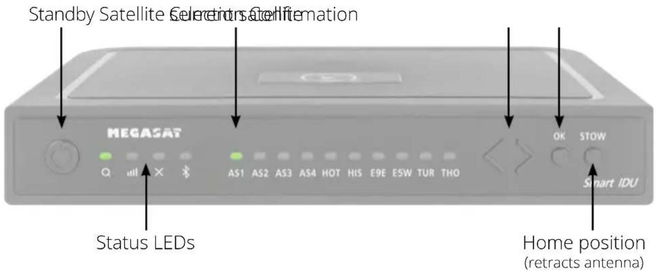
3. Satellite search with the control unit
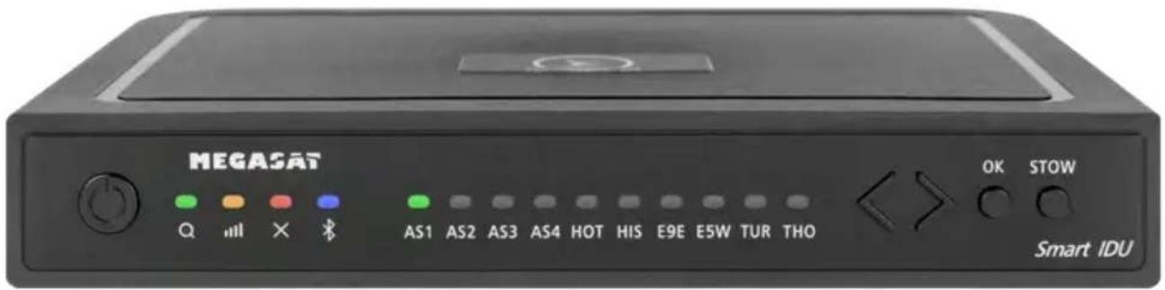
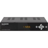
3.1 Designation of the respective LEDs and keys

Search-LED
Flashing during satellite search

Reception-LED
Lights up when a satellite is found

Error-LED
Lights up in case of a malfunction

Bluetooth-LED
Lights when connected

Satellite-LED
Astra 1 (19,2° East)

Satellite-LED
Astra 2 (28,2° East)

Satellite-LED
Astra 3 (23,5° East)

Satellite-LED
Astra 4 ( 4° East)

Satellite-LED
Hotbird (13° East)

Satellite-LED
Hispasat (30° West)

Satellite-LED
Eutelsat 9 B (9° East)
Satellite-LED
Eutelsat 5 West (5° West)

Satellite-LED
Turksat (42° East)

Satellite-LED
Thor (0,8° West)

Standby-button
Switches the control unit on / off

Arrow-button
Changing satellites

OK-button
Confirms the satellite selection

STOW-button
Moves the antenna to the home position
3. Satellite search with the control unit
3.2 Satellite search
| 1. |  | the control unit on at the standby button. |
| 2. |  | The search LED flashes green during the search process. |
| 3. |  | The satellite LED of the last used satellite flashes green. |
| 4. |  | To change the satellite, you must change the satellite with the arrow keys within approx. 3-5 seconds while the LEDs are flashing. Later changing is only possible if the antenna has found a satellite before. |
| 5. |  | Confirm the satellite selection with the OK button or wait 3-5 seconds until the satellite logs in automatically. |
| 6. |  | After the selected satellite has been found, the reception LED will light up orange. |
| 7. |  | If the selected satellite was not found, the Error LED will light red. |
| 8. |  | After successful search, you can switch off the control unit again at the standby key. |
Note:
If you want to start the search at another location, simply press the Standby key to search for the last selected satellite.
Retract the antenna to the home position
| 1. |  | ssary, switch the control unit on at the standby button. |
| 2. |  | Press the STOW button to retract the antenna. |
4. Mobile App to control the antenna

With the app, the satellites can be changed via the smartphone or tablet. Future firmware updates for the control unit can also be made. The app is available free of charge from the App Store (iOS) or the Google Play Store (Android). Search for the name „Megasat“ in the respective store.
Note: Make sure that Bluetooth® is activated on the mobile device and that you are no further than 10 metres away from the control unit.
4.1 Connecting the control unit to the mobile device
-
After the app has opened, the following start screen appears.
-
Now switch on the control unit. The name of the control unit will then appear in the selection menu. Click on it.


4. Mobile App to control the antenna
- On the main interface of the app there are now various options:
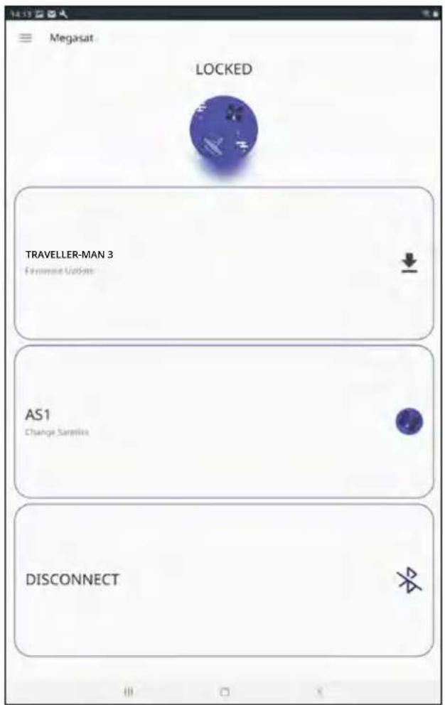
Firmware update of the antenna
Change satellites
Disconnect Bluetooth® connection
4. Mobile App to control the antenna
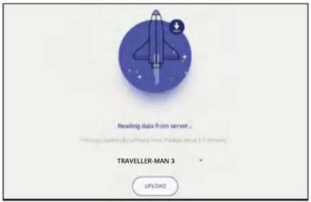
4.2 Firmware Update of the Antenna
- Tap the button to open the up-date menu.

- The app checks whether a newer version of the firmware is currently available:
Reading data from server...

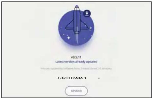
- If no new firmware is available, the current version number is displayed and the following message appears:
Latest version already updated

- If a new firmware is available, the new version number is displayed and the following message appears:
New software available
Then tap the „Upload“ button to update the antenna.

4. Mobile App to control the antenna
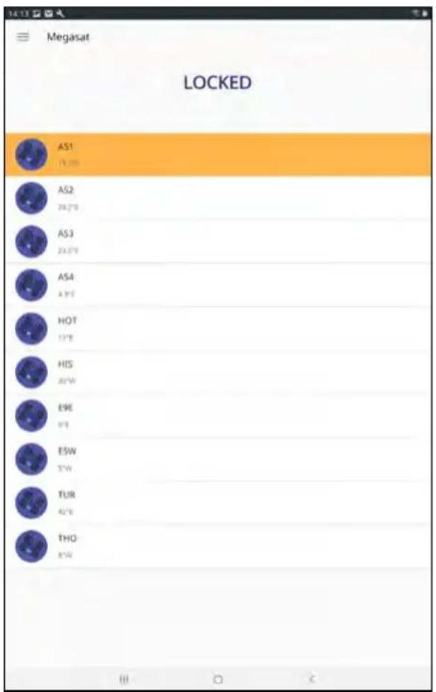
4.3 Change satellite
-
Tap on the button to open the satellite list.
-
Select the desired satellite. After approx. 3-5 seconds the satellite will be searched automatically.
AS1 Astra 1 (19,2° East)
AS2 Astra 2 (28,2° East)
AS3 Astra 3 (23,5° East)
AS4 Astra 4 (4° East)
HOT Hotbird (13° East)
HIS Hispasat (30° West)
E9E Eutelsat 9 B (9° East)
E5W Eutelsat 5 West (5° West)
TUR Türksat (42° East)
THO Thor (0,8° West)
Note:
A satellite change is only possible if the antenna has found a satellite before.

4.4 Disconnect Bluetooth® connection
Tap the button to disconnect the Bluetooth® connection between mobile device and control unit.

5. Troubleshooting
No satellite signal
Objects such as trees, bridges and large houses located at the satellite's angle of incidence cause the signal to be lost. If the satellite signal is lost due to severe weather conditions, the current program of the TV or receiver will be interrupted (the picture will pixelate, freeze or disappear). When the weather conditions allow good reception again, the TV picture will be restored.
Is there dirt on the antenna?
Heavy dirt on the housing can cause reception problems.
Is everything correctly connected and switched on?
Make sure that the TV and the receiver are connected correctly and that the receiver is correctly set for satellite reception. Are all cables connected correctly and the connections screwed tightly onto the coaxial cable? Also check the coaxial cable for kinks.
Footprint of the satellite
Satellites are in fixed positions above the equator in orbit. In order to receive the TV signals, the receiving location must be within the footprint. Use the diagram to check whether your location is within the satellite's footprint. In the peripheral areas of the footprint, reception interference may occur.
Satellite frequency of a TV channel was changed
TV stations change their frequency sporadically, which then no longer matches the frequency in the receiver. Ask for the current frequency of the channel.
The firmware of the control unit is outdated
If transponders on the satellite are changed, the antenna may no longer be able to find the satellite. Update the firmware of the control unit to get the latest transponder information.
The mobil app does not connect to the control unit
Make sure that Bluetooth® on your mobile device is switched on and that you are in the direct vicinity of the control unit (max. 10 metres).
6. Footprint
Astra 1 Hotbird

Note: In the outlying areas of the footprint there may be interference.
7. Mounting dimensions

Note:
Weight and dimensions are not absolutely exact values.
Technical details can be changed at any time without prior notice.
Conformity information
Hereby, Megasat Werke GmbH declares that the following product is in compliance with the essential requirements and other relevant provisions of directives 2014/30/EU (EMC), 2014/35/EU (LVD) and 2014/53/EU (RED):
Traveller-Man 3 (Art-No. 1500196)
The declaration of conformity for this product is located at the company: Megasat Werke GmbH, Brückenstraße 2a, D-97618 Niederlauer
The declaration of conformity can be downloaded from our homepage: www.megasat.tv/support/downloads
PRODUCT REGISTRATION
Registering your Megasat product gives you access to our automatic e-mail notifications. If your product requires new firmware, you will be notified by e-mail.
To register, please visit our homepage www.megasat.tv
You can find the form under Support ⇒ Product registration
Version: 1.1 (January 2023)
Technical changes, misprint and errors reserved.
Traveller-Man 3
Mode d'emploi
IMPORTANT!!!

ATTENTION!
Unité d'antenne
2. Installation
2. Installation
Remarque: Make sure that Bluetooth ® is activated in the mobile device and that you are no further than 10 metres away from the control unit.
Reading data from server...
Latest version already updated
HOT Hotbird (13° Est)
HIS Hispasat (30° Ouest)
E9E Eutelsat 9 B (9° Est)
E5W Eutelsat 5 West (5° Ouest)
TUR Türksat (42° Est)
THO Thor (0,8° Ouest)
Remarque:
Remarque:


- BEDIENUNGSANLEITUNG
- WICHTIG
- EINFÜHRUNG
- 1.3 SYSTEMKOMPONENTEN
- ACHTUNG
- ANTENNENEINHEIT
- INSTALLATION
- HINWEIS
- IMPORTANT
- INTRODUCTION
- SATELLITE SEARCH WITH THE CONTROL UNIT
- MOBILE APP FOR CONTROLLING THE ANTENNA
- 1.1 SAFETY INFORMATION
- 1.2 DELIVERY
- 1.3 SYSTEM COMPONENTS
- WARNING
- ANTENNA UNIT
- CONTROL UNIT
- NOTE
- GENERAL INFORMATION
- 2.1 SETTING THE ANTENNA TO INSTALLATION MODE
- 2.2 INSTALLATION ON THE ROOF
- 2.3 GLUING INSTRUCTIONS
- 2.3 INDOOR INSTALLATION
- 2.5 CONNECTION OF THE COMPONENTS
- IGNITION PLUS
- POWER SUPPLY
- 2.5 CONTROL UNIT
- 2.6 SATELLITE BROADCASTING
- 3.1 DESIGNATION OF THE RESPECTIVE LEDS AND KEYS
- SEARCH-LED
- RECEPTION-LED
- ERROR-LED
- BLUETOOTH-LED
- SATELLITE-LED
- STANDBY-BUTTON
- ARROW-BUTTON
- OK-BUTTON
- STOW-BUTTON
- 3.2 SATELLITE SEARCH
- RETRACT THE ANTENNA TO THE HOME POSITION
- MOBILE APP TO CONTROL THE ANTENNA
- 4.1 CONNECTING THE CONTROL UNIT TO THE MOBILE DEVICE
- 4.2 FIRMWARE UPDATE OF THE ANTENNA
- 4.3 CHANGE SATELLITE
- 4.4 DISCONNECT BLUETOOTH® CONNECTION
- TROUBLESHOOTING
- NO SATELLITE SIGNAL
- IS THERE DIRT ON THE ANTENNA
- IS EVERYTHING CORRECTLY CONNECTED AND SWITCHED ON
- FOOTPRINT OF THE SATELLITE
- SATELLITE FREQUENCY OF A TV CHANNEL WAS CHANGED
- THE FIRMWARE OF THE CONTROL UNIT IS OUTDATED
- THE MOBIL APP DOES NOT CONNECT TO THE CONTROL UNIT
- FOOTPRINT
- ASTRA 1 HOTBIRD
- MOUNTING DIMENSIONS
- CONFORMITY INFORMATION
- TRAVELLER-MAN 3 (ART-NO. 1500196)
- PRODUCT REGISTRATION
- MODE D'EMPLOI
- ATTENTION
- UNITÉ D'ANTENNE
- REMARQUE
Brand : MEGASAT
Model : TravellerMan 3
Category : Receiver