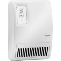
H 260E eco - Heating DIMPLEX - Free user manual and instructions
Find the device manual for free H 260E eco DIMPLEX in PDF.


| Product type | Bathroom fan heater |
| Brand | Dimplex |
| Model | H 260E eco |
| Dimensions (W x H x D) | 300 x 405 x 120 mm |
| Weight | 3.2 kg |
| Power supply | 230 V ~ 50 Hz, 1/N/PE |
| Rated heat output | 1.0 kW |
| Protection rating | IP24 |
| Mounting | Wall-mounted, horizontal installation |
| Heating type | Forced convection (fan) |
| Control | Electronic with thermostat, weekly programming, adaptive start |
| Operating modes | Timer, manual, frost protection (7 °C), countdown timer |
| Special functions | Cold air fan (FAN), power reduction (LO), key lock, program copy |
| Display | Digital screen, touch keys |
| Safety | Overload limiter (auto shut-off), child protection (< 3 years keep away, 3-8 years under supervision), hot surface |
| Cleaning and maintenance | Soft damp cloth, vacuum cleaner for dust; do not use abrasive products |
| Warranty | 2 years |
| Disposal | Do not dispose of with household waste, local recycling center |
Frequently Asked Questions - H 260E eco DIMPLEX
User questions about H 260E eco DIMPLEX
0 question about this device. Answer the ones you know or ask your own.
Ask a new question about this device
Download the instructions for your Heating in PDF format for free! Find your manual H 260E eco - DIMPLEX and take your electronic device back in hand. On this page are published all the documents necessary for the use of your device. H 260E eco by DIMPLEX.
USER MANUAL H 260E eco DIMPLEX
natural_image
White BCDimplex electric heater with digital display and ventilation grille (no text or symbols on main body)DCDimplex
| Montage- und Gebrauchsanweisung | Deutscheng |
| Installation and Operating Instructions | Françaislato |
| Instructions de montage et d’utilisation | |
| Istruzioni d’uso e di montaggio | Nederlands |
| Montage- en gebruiksaanwijzing |
Fan heater for bathrooms
natural_image
Technical line drawing of a two-view device with front and top views (no text or symbols)natural_image
Technical line drawing of a mechanical component with dimension arrows and internal features (no text or symbols)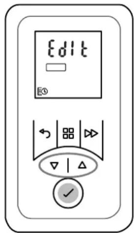
1. Notes for the user
i NOTE
Dear customer,
Keep these instructions in a safe place and pass them on to possible future owners.
CAUTION!
This device can be used by children aged 8 and over and by persons with limited physical, sensory or mental aptitude or lack of experience and/or knowledge, providing they are supervised or have been instructed in the safe use of the device and understand the associated potential dangers. Children must not play with the device. Cleaning and user maintenance may not be carried out by children without supervision!
CAUTION!
Children younger than 3 years of age must be kept away unless they are supervised constantly. Children between the ages of 3 and 8 may switch the device on and off if they are supervised or have been instructed in the safe use of the device and have understood the resulting dangers, providing that the device is positioned or installed in its normal place of use!
CAUTION!
Children between the ages of 3 and 8 may not switch on the device, clean the device or carry out maintenance!
CAUTION!
The device carries the symbol shown on the right, which indicates that the heating device must under no circumstances be covered with any objects.

CAUTION!
Some parts of the device can get very hot and cause burns. Particular caution must be taken with children or vulnerable people!
CAUTION!
Do not operate the heating device in rooms where highly inflammable substances are used (e.g. solvents).
CAUTION!
Install the device in such a manner that it cannot be touched by a person in the bathtub or under the shower.
CAUTION!
If the power cable is damaged, it must be replaced by the manufacturer or after-sales service representative or a person with comparable qualifications for switching off danger sources!
CAUTION!
In order to avoid a hazard due to inadvertent resetting of the thermal cutout, this appliance must not be supplied through an external switching device, such as a timer or connected to a circuit that is regularly switched on and off by the utility.
CAUTION!
Rooms can become overheated if left unattended whilst being heated. Persons who are not able to vacate the room if the temperature becomes too high can thus be placed in danger.
i NOTE
Use device for room heating within enclosed rooms only.
2. Assembly, installation, minimum clearance

CAUTION!
Do not install the device directly below a wall socket.
natural_image
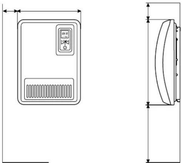
Technical line drawing of a two-view device with front and top views (no text or symbols)The minimum clearances must be observed.
In addition, a clearance of 750 mm is to be maintained in front of the unit.
The heating device must be aligned horizontally and installed on a vertical wall (see illustration).
All dimensions in mm
During assembly, the safety area must be complied with according to the current installation regulations.
The socket or supply connection socket must be accessible after installation.
Make sure that the inflow and outflow of air at the device are unimpeded.

NOTE
Installation on wooden walls is permissible.
Wall mounting

CAUTION!
The original wall bracket supplied on the rear of the device must be used!

NOTE
Look out for electric cables or pipework in the wall when drilling.
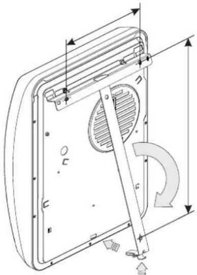
■ Unlock the wall bracket (A) and remove from the device.
- Drill mounting holes for the wall bracket and insert the dowels.
- Align the wall bracket and firmly screw it onto the wall.
■ Hang the device on the wall mount.
■ Pivot down the heater and push into place (B).
natural_image
Technical line drawing of a mechanical component with dimension arrows and internal features (no text or symbols)3. Electrical connection
The voltage specified on the type plate must match the line voltage.
The cable must not be in contact with the casing.
It is recommended that a separate circuit be provided for the power supply.
Insert the plug in the socket. The plug must always be accessible in case of emergencies.
The unit must be connected only to an earthed power outlet.
4. Overload protector
For your safety, the heating device is equipped with an overload protector. If the air circulation is interrupted (e.g. due to the air grille being covered or closed), the device switches off automatically. Err35 is shown on the display.
In this case, the power supply to the heating device should be disconnected for a few minutes (disconnect the plug, switch off the fuse) to allow the device to cool down sufficiently.
Before recommissioning the device, remove the reasons for the overload protector being triggered.
5. Cleaning
The device must be disconnected from the mains and allowed to cool down before cleaning and maintenance. Clean the outside of the device using a soft, damp cloth. Do not use scouring powder or furniture polish as this may damage the surface.
Dust which gathers inside the device can be removed from the outside using a vacuum cleaner.
6. Control description
6.1 Control unit
The heating device is equipped with a configurable electronic control, consisting of a display and six touchscreen keys. The control unit is located on the top on the right. All settings can be selected using the six keys on the user interface.
The set functions and values are shown on the display.
6.3 Display
The display lights up when a key is activated. If no changes are made for a prolonged period, the display switches off. If no key is pressed, the display returns to the main menu after 30 seconds.
The 4-digit device PIN is displayed by pressing the ENTER key.
7. Operating modes
7.1 Timer week program
Up to four heating programs (On/Off) can be set for each weekday. A room temperature can be specified for each heating program.
TIMER symbol is shown in the display.
7.2 Manual operation
Manual specification of the room temperature.
MANUAL symbol is shown in the display.
7.3 Frost protection
Specified frost protection temperature of 7°C.
FROST symbol is shown in the display.
HINWEIS
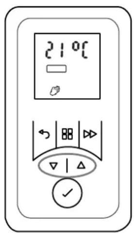
The room temperature can be changed with the ▲ or
▼ keys in all operating modes.
In the timer program, this change is only carried out for the current time program.
8. Commissioning
8.1 Setting the date and time
The control includes a real-time clock with calendar function.
6.2 Key functions
MAIN MENU
Setting date and time
Timer week program
Manual operation
Frost protection mode
BACK
Return to the previous program item
Keys ▲ ▼
Used to navigate through the menu and to change the setting values.
ENTER
Saving settings.
ADVANCE
Special functions such as switching to the next programme item in timer mode or activating the run-back timer.
The date and time are set with the following steps:
Press the MENU key.
Press ▲ or ▼ to select the DATE & TIME symbol. The symbol flashes.
Press the ENTER key. The hours display flashes.
Use ▲ or ▼ to set the hours and minutes. Confirm every position specified with the ENTER key.
■ The time is saved and the display dAY flashes briefly.
■ Use ▲ or ▼ to set the day.
■ Confirm every position specified with the ENTER key. 1-12 display flashes briefly.
■ Use ▲ or ▼ to set the month.
■ Confirm every position specified with the ENTER key. YEAr display flashes briefly.
■ Use ▲ or ▼ to set the year.
■ Confirm every position specified with the ENTER key. dSt (summer time) ON display flashes.
■ Recommendation: Confirm the ON display with the ENTER key. This ensures the system will automatically change to summer/winter time.
9. Operation
9.1 Standby mode (waiting position)
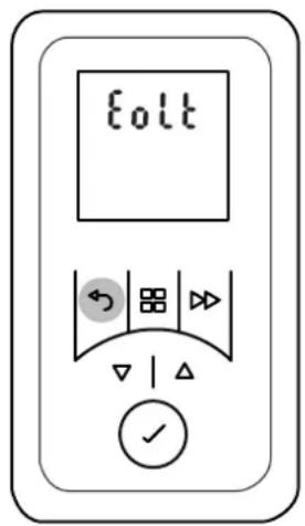
- Hold down the BACK key until the display Eolt appears. The heating device is in standby mode.
■ To return to the previous operating status, briefly press the BACK key.
9.2 Switching heating operation on/off
Switching heating operation on
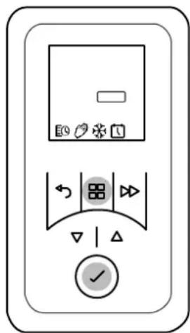
- Press the MAIN MENU key. The TIMER symbol flashes.
- Press ▲ or ▼ to select the required operating mode. The symbol flashes.
■ Confirm with the ENTER key.
Switching heating operation off
- Press the MAIN MENU key. The TIMER symbol flashes.
■ Press ▲ or ▼ to select the OFF symbol. The OFF symbol flashes.
■ Confirm with the ENTER key.
i NOTE
Heating operation Off does not mean that the device is completely disconnected from the power supply. To disconnect the device from the electricity network, please pull out the plug.
9.3 Timer week program
The timer is pre-programmed at the factory. Four time blocks, which can be adapted individually for each weekday, are available per day.
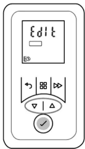
To change these profiles, carry out the following steps:
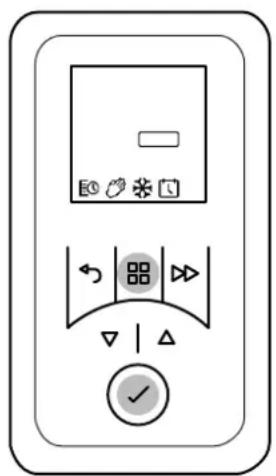
■ Press the MENU key. The TIMER symbol flashes.
■ Press the ENTER key. The ON symbol flashes.
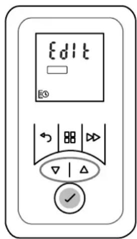
■ Press ▲ or ▼ to select the EdIt display. EdIt display flashes.
■ Press the ENTER key. The weekday flashes.
■ Use ▲ or ▼ to select the day.
1 = Monday 5 = Friday
2 = Tuesday 6 = Saturday
3 = Wednesday 7 = Sunday
4 = Thursday
■ Press the ENTER key. P1 (Program 1) flashes.
■ Press the ENTER key. Switch-on time flashes.
■ Use ▲ or ▼ to set the hours and minutes. Confirm every position specified with the ENTER key. Room temperature flashes.
■ Use ▲ or ▼ to set the temperature. Press the ENTER key. Switch-off time flashes.
■ Use ▲ or ▼ to set the hours and minutes. Confirm every position specified with the ENTER key. P2 (Program 2) flashes.
■ The programs P2, P3 and P4 can be set in the same way.
- To copy the newly set programs P1 - P4 to other days, hold down the ADVANCE key. COPY display flashes briefly. The day values selected are copied.
■ Press ▲ or ▼ to select a new weekday. The week-day flashes.
- Hold down the ENTER key. PStE display flashes briefly. The day values copied are assigned to the new weekday.
■ Then press the MAIN MENU key.
9.4 Manual operation
i NOTE
The timer week program is deactivated in manual operation.
The room temperature specification takes place manually.
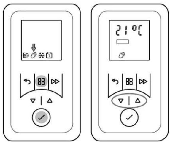
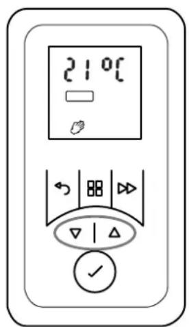
■ Press the MENU key. The TIMER symbol flashes.
■ Press ▲ or ▼ to select the MANUAL symbol. The MANUAL symbol flashes. Press the ENTER key.
■ Use ▲ or ▼ to set the room temperature.
9.5 Frost protection
Specified frost protection temperature of 7°C.
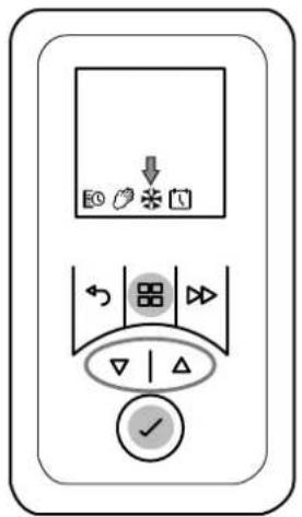
■ Press the MENU key. The TIMER symbol flashes.
Press ▲ or ▼ to select the FROST symbol. The FROST symbol flashes. Press the ENTER key. FROST symbol and temperature 7°C are displayed.
i NOTE
The pre-set temperature value of 7^ C can be changed with ▲ or ▼.
9.6 Run-back timer
The run-back timer can be used to activate a one-off, time-limited heating program.
Basic settings
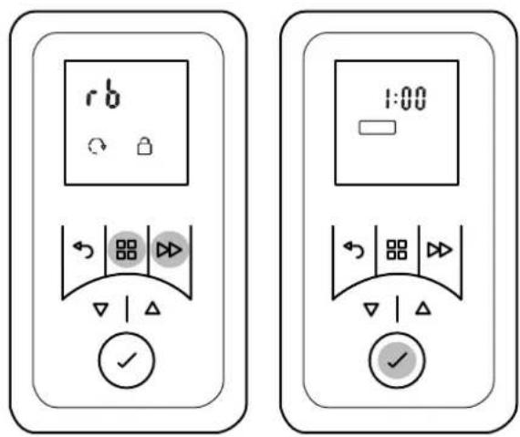
■ Hold down the MENU and ADVANCE keys until the rb display flashes.
■ Press the ENTER key. ON/OFF display flashes.
■ Press ▲ or ▼ to select the ON display. Press the ENTER key. Maximal run-back time flashes.
■ Use ▲ or ▼ to set the maximal run-back time.
| Maximal run-back time | Press the ADVANCE key: | |||
| 1 time | 2 times | 3 times | 4 times | |
| 30 minutes 00:15 | 00:20 | 0:25 | 00:30 | |
| 01:00 h (factory) | 00:15 | 00:30 | 00:45 | 01:00 |
| 01:30 h 00:15 | 00:30 | 01:00 | 01:30 | |
| 02:00 h 00:30 | 01:00 | 01:30 | 02:00 | |
| 04:00 h 01:00 | 02:00 | 03:00 | 04:00 | |
| 06:00 h 01:30 | 03:00 | 04:30 | 06:00 | |
| 08:00 h 02:00 | 04:00 | 06:00 | 08:00 | |
■ Press the ENTER key. Room temperature flashes.
■ Where necessary, change the room temperature with ▲ or ▼. Confirm with the ENTER key.
Run-back timer On
i NOTE
Not possible if operating mode TIMER is selected.
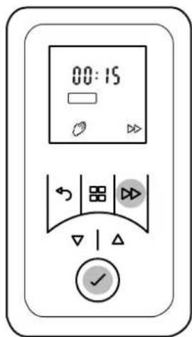
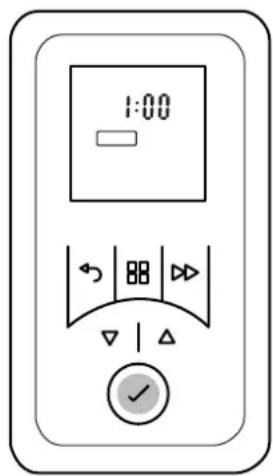
■ Press the ADVANCE key. Run-back time flashes.
■ The run-back time can be changed by pressing the ADVANCE key several times.
■ Press the ENTER key. Run-back timer = ON.
Run-back timer Off
■ Press the ADVANCE key several times until the OFF display flashes.
■ Press the ENTER key. Run-back timer = OFF.
9.7 Adaptive start-up
i NOTE
This function is executed only when the operating mode TIMER is selected.
This function guarantees that the set room temperature is achieved exactly at the start of the switch-on time.
Example:
In the timer menu, a set room temperature of 22^ C is specified for 07:00. The current room temperature is 17^ C. The heating device switches on early so that the specified room temperature of 22^ C is reached by 07:00.
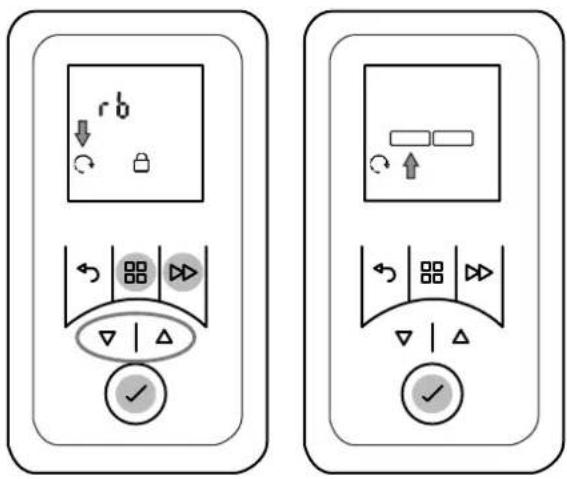
■ Hold down the MENU and ADVANCE keys until the rb display flashes.
■ Press ▲ or ▼ to select the ADAPTIVE START symbol. The symbol flashes.
■ Press the ENTER key.
■ Press ▲ or ▼ to select ON or OFF to switch the function on or off.
10. Options
10.1 Blocking keys
Key functions are blocked using a freely selectable four-digit numerical code.
i NOTE
The function of the run-back timer and switching to the next programme item in timer mode is also possible with active key lock.
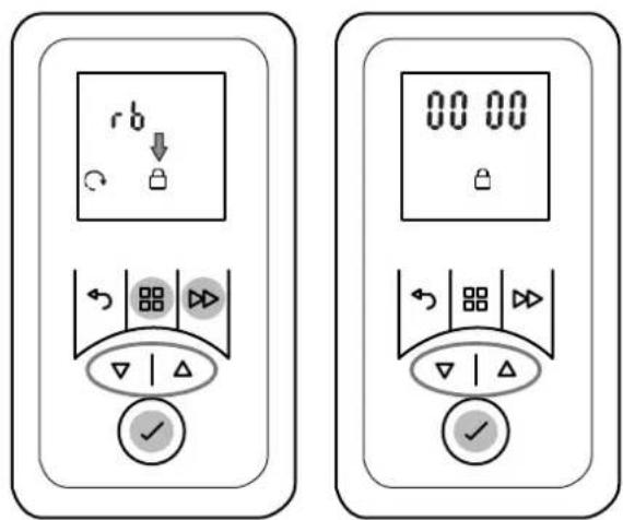
Specifying unlock code
- Hold down the MENU and ADVANCE keys until the rb display flashes.
■ Press ▲ or ▼ to select the BLOCKED symbol. The symbol flashes.
■ Press the ENTER key. The number display flashes.
■ Press ▲ or ▼ to specify the number for the unlock code. Confirm every position specified with the ENTER key.
i NOTE
If the specified lock code is not available, the block can be cleared by entering the number 4115.
Unlocking keys
■ Press any button. The four-digit numerical code 0000 is displayed.
■ Press ▲ or ▼ to enter the number for the unlock code. Confirm every position specified with the ENTER key.
10.2 Reducing heat output, cold air mode
Model H 260E
The maximal heat output of 2 kW can be reduced to 1 kW. Alternatively, the device can be operated as a cold air fan.
Model H 260E eco
The device can be alternatively operated as a cold air fan.
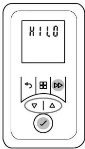
■ Hold down the ADVANCE key until the HILO display appears.
■ Press ▲ or ▼ to select HI or LO or FAN. The display means:
HI = normal operation, full fan speed.
LO = fan speed reduction, heat reduction to 1 kW on model H 260E.
FAN = cold air mode (no heat output).
■ Confirm selected setting with ENTER.
10.3 Minimum room temperature
This function can be used to ensure that a minimum room temperature is specified even during OFF times, for example in timer mode (week program).
i NOTE
The specification also applies to the runback timer function. Frost protection mode has priority.
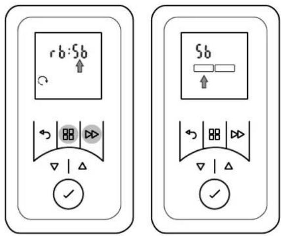
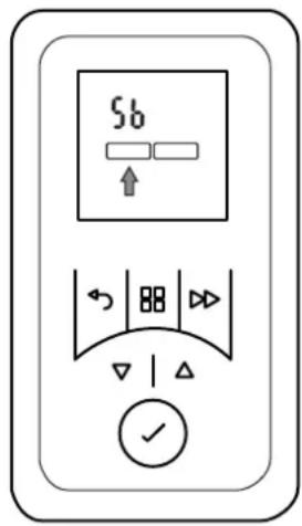
■ Hold down the MENU and ADVANCE keys until the rb display flashes.
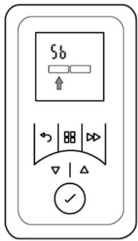
■ Press ▲. The Sb display flashes.
■ Press the ENTER key. The ON symbol flashes.
■ Press the ENTER key. The minimum room temperature (factory setting 16°C) flashes.
■ Use ▲ or ▼ to set the minimum room temperature and confirm with ENTER.
■ Press the BACK key to return to the standard display.
10.4 Reset to factory settings
Resets all settings made by the user to the pre-set factory settings.
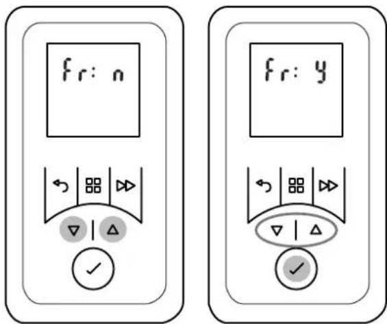
■ Hold down ▲ and ▼ until the Fr n display appears.
■ Press ▲ or ▼ to select the Y display. The symbol flashes.
■ Press the ENTER key. All values are reset to the factory settings. Time display appears.
■ Set the time and date.
10.5 Temperature unit
Display can be set to degrees Celsius and degrees Fahrenheit.
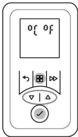
■ Hold down the MENU key until °C display flashes.
■ Press ▲ or ▼ to select °C or °F.
■ Confirm with the ENTER key.
i NOTE
The temperature unit ^ C is customary in most European countries.
11. Warranty
This product is supplied with a two-year warranty according to our terms of guarantee.
12. Note on disposal
Do not dispose of the unit with general household waste. The device must be taken to a local waste disposal plant.

13. Technical data
| Model reference H 260E H 260E eco | |||
| Nominal voltage 1/N/PE, 230 | V~, 50 Hz | ||
| Degree of protection IP24 | |||
| Dimensions (W x H x D) 300 | x 405 x 120 mm | ||
| Weight 3.2 kg | |||
| Heat output | |||
| Nominal heat output | P_nom | 2.0 kW 1.0 kW | |
| Minimum heat output (indicative) | P_min | 1.0 kW 1.0 kW | |
| Maximum continuous heat output | P_max, C | 2.0 kW 1.0 kW | |
| Auxiliary electricity consumption | |||
| At nominal heat output | e|_max | 0.0 W | 0.0 W |
| At minimum heat output | e|_min | 0.0 W | 0.0 W |
| In standby mode | e|_SB | 0.5 W | 0.5 W |
| Type of control | |||
| Electronic room temperature controller with week program, adaptive control of the heating start and operating time limit | |||
2. Montage, installation, distances minimales

ATTENTION!
natural_image
Technical line drawing of a two-view device with front and top views (no text or symbols)natural_image
Technical line drawing of a mechanical component with dimension arrows and internal features (no text or symbols)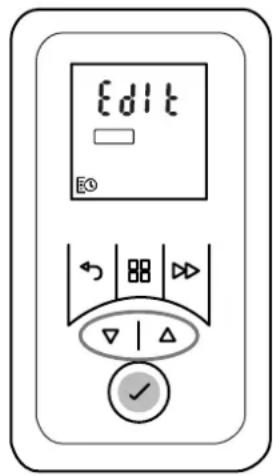
natural_image
Technical line drawing of a two-view device with front and top views (no text or symbols)natural_image
Technical line drawing of a mechanical component with dimension arrows and internal features (no text or symbols)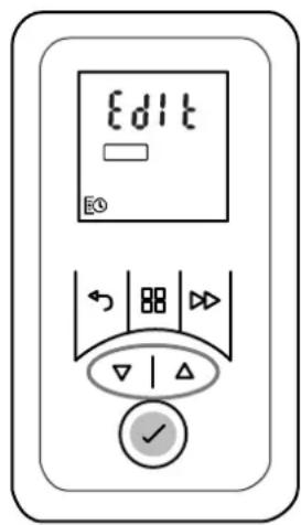
natural_image
Technical line drawing of a two-view device with front and top views (no text or symbols)natural_image
Technical line drawing of a mechanical component with dimension arrows and internal features (no text or symbols)6.2 Toetsfuncties
HOOFDMENU
9.1 Stand-bymodus (wachtstand)
Deblokkeringscode vastleggen
- DCDimplex
- Notes for the user
- i NOTE
- CAUTION!
- Assembly, installation, minimum clearance
- NOTE
- Wall mounting
- Electrical connection
- Overload protector
- Cleaning
- Control description
- Control unit
- Display
- Operating modes
- Timer week program
- Manual operation
- Frost protection
- HINWEIS
- Commissioning
- Setting the date and time
- Key functions
- MAIN MENU
- BACK
- Keys ▲ ▼
- ENTER
- ADVANCE
- Operation
- Standby mode (waiting position)
- Switching heating operation on/off
- Switching heating operation on
- Switching heating operation off
- Timer week program
- Manual operation
- Frost protection
- Run-back timer
- Run-back timer On
- Run-back timer Off
- Adaptive start-up
- Example:
- Options
- Blocking keys
- Specifying unlock code
- Unlocking keys
- Reducing heat output, cold air mode
- Model H 260E
- Model H 260E eco
- Minimum room temperature
- Reset to factory settings
- Temperature unit
- Warranty
- Note on disposal
- Technical data
- Montage, installation, distances minimales
- ATTENTION!
- Toetsfuncties
- HOOFDMENU
- Stand-bymodus (wachtstand)
- Deblokkeringscode vastleggen
Brand : DIMPLEX
Model : H 260E eco
Category : Heating