TCS115BAN - Speaker Turbosound - Free user manual and instructions
Find the device manual for free TCS115BAN Turbosound in PDF.
| Product Type | Powered Subwoofer |
| Brand | Turbosound |
| Model | TCS115BAN |
| Loudspeaker | 15" (38 cm) with high-temperature voice coil |
| Amplifier | Built-in, Class D, with switch-mode power supply |
| Continuous Power | 1000 W RMS |
| Peak Power | 2000 W |
| Frequency Response | 45 Hz – 150 Hz (-10 dB) |
| Maximum SPL | 130 dB SPL peak |
| Input Connectors | 1 x combo XLR/TRS (balanced), 1 x XLR LINK |
| Network Connectors | 1 x ULTRANET IN (EtherCON), 1 x ULTRANET THRU (EtherCON) |
| USB Connector | Type B for firmware update and PC control |
| Power Supply | 100-240 V AC, 50/60 Hz, with locking powerCON connector |
| Built-in DSP | Parametric EQ, crossover, limiter, delay (300 ms), 8 anti-feedback filters |
| Factory Presets | 20 user presets and curve presets (Brix, Tailteux, etc.) |
| Enclosure Material | Birch plywood with impact-resistant coating |
| Grille | Steel with anti-dust acoustic foam |
| Rigging Points | 8 x M10 integrated (top, bottom, sides, rear) |
| Mounting Options | WB-35 wall brackets, CB-35 ceiling brackets, TCS-FK1/FK2 flying kits |
| Dimensions (H x W x D) | 500 x 600 x 700 mm |
| Net Weight | 35 kg |
| Maintenance and Cleaning | Dust the grille with a dry cloth; do not use liquid products |
| General Information | Indoor use, tropical or moderate up to 45°C; disposal via WEEE |
Frequently Asked Questions - TCS115BAN Turbosound
User questions about TCS115BAN Turbosound
0 question about this device. Answer the ones you know or ask your own.
Ask a new question about this device
Download the instructions for your Speaker in PDF format for free! Find your manual TCS115BAN - Turbosound and take your electronic device back in hand. On this page are published all the documents necessary for the use of your device. TCS115BAN by Turbosound.
USER MANUAL TCS115BAN Turbosound
natural_image
Row of black outdoor audio equipment units with no visible text or symbolsTCS-AN SERIES
TCS122/64-AN (-WH), TCS122/94-AN (-WH), TCS122/96-AN (-WH), TCS152/64-AN (-WH), TCS152/94-AN (-WH), TCS152/96-AN (-WH), TCS115B-AN (WH), TCS218B-AN (WH)
Arrayable 2,500 Watt 2 Way Full Range Loudspeakers with Dendritic Waveguides 6,000 Watt and Arrayable 3,000 Watt Subwoofers Klark Teknik DSP Technology and ULTRANET Networking
2 TCS-AN SERIES Quick Start Guide 3
EN
ES
EN Important Safety Instructions
Terminals marked with this symbol carry electrical current of sufficient magnitude to constitute risk of electric shock. the only high quality professional speaker tables with 15" TS or twist-locking plugs pre installed. All other installation or modification should be performed only by qualified personnel.
This symbol, wherever it appears, alerts you to the presence of uninsulated dangerous voltage inside the enclosure – voltage that may be sufficient to constitute a risk of shock.
This symbol, wherever it appears, alerts you to important operating and maintenance instructions in the accompanying literature. Please read the manual.
Caution To reduce the risk of electric shock, do not remove the top cover (or the rear section). No user serviceable parts include. Refer servicing to qualified personnel.
Caution To reduce the risk of fire or electric shock, do not expose this appliance to rain and moisture. The apparatus shall not be exposed to dripping or splashing liquids and no objects filled with liquids, such as wares, shall be plated on the apparatus.
Caution These service instructions are for use by qualified service personnel only. To reduce the risk of electric shock do not perform any servicing other than that contained in the operation instructions. Repairs have to be performed by qualified service personnel.
- Read these instructions.
- Keep these instructions.
- Here all warnings.
- Follow all instructions.
- Do not use this apparatus near water.
- Clean only with dry cloth.
- Do not lock any ventilation openings, install in accordance with the manufacturer's instructions.
-
Do not install near any heat sources such as rotators, heat registers, stoves, or other apparatus (including amplifiers) that produce heat.
-
Do not defeat the safety purpose of the polarized or grounding-type plug. A polarized plug has two blades with one wider than the other. A grounding-type plug has two blades and a third grounding prong. The wide blade or the third prong are provided for your safety. If the provided plug does not fit into your outlet, consult an electrician for replacement of the obsoiete outlet.
-
Protect the power cord from being vialled on or pinched particularly at plugs, convenience receptacles, and the point where they exit from the apparatus.
- Use only attachments/accessories specified by the manufacturer.

- Use only with the cart, stand, tripod, bracket, or table specified by the manufacturer, or sold with the apparatus. When a cart is used, use caution when moving the cart/apparatus combination to avoid
injury from tip-over.
-
Unplug this apparatus during lightning storms or when unused for long periods of time.
-
Refer all servicing to qualified service personnel. Servicing is required when the apparatus has been damaged in any way, such as power supply cord or plug in damaged, liquid has been spilled or objects have fallen into the apparatus, the apparatus has been exposed to rain or moisture, does not operate normally, or has been dropped.
-
The apparatus shall be connected to a MUNG socket outlet with a protective earthing connection.
-
Where the MAINS plug or an appliance coupler is used as the disconnect device, the disconnect device shall remain nearly operable.

- Correct disposal of this product: This symbol indicates that this product must not be disposed of with household waste, according to the WEE Directive (2012/19/EU) and
should be taken to a collection center licensed for the recycling of waste electrical and electronic equipment (ELEC). The misunderstanding of this type of waste could have a possible negative impact on the environment and human health due to potentially hazardous substances that are generally associated with ELEC. At the same time, your cooperation in the correct disposal of this product will contribute to the efficient use of natural resources. For more information about where you can take your waste equipment for recycling, please contact your local city office, or your household waste collection service. 18. Do not install in a confined space, such as a book case or similar unit.
-
Do not place naked flame sources, such as lighted candles, on the apparatus.
-
Please keep the environmental aspects of battery disposal in mind. Batteries must be disposed-of at a battery collection point.
-
This apparatus may be used in tropical and moderate climates up to 45°C.
LEGAL DISCLAIMER
Music Tribe accepts no liability for any loss which may be suffered by any person who relies either wholly or in part upon any description, photograph, or statement contained herein. Technical specifications, appearances and other information are subject to change without notice. All trademarks are the property of their respective owners. Midas, Mark Tekink, Lab Suggers, Lake, Tammy, Turbosound, TC Electronic, TC Helicon, Behringer, Bugera, Institut Microraphes and Codaudio are trademarks or registered trademarks of Music Tribe Global Brands Ltd. © Music Tribe Global Brands Ltd. 2021 All rights reserved.
LIMITED WARRANTY
For the applicable warranty terms and conditions and additional information regarding Music Tribe's Limited Warranty, please see complete details online at musictribe.com/warranty.
ES
BESCHRÄNKTE GARANTIE
Thank you for choosing a Turbosound loudspeaker product for your application. If you would like further information about this or any other Turbosound product, please visit our website at turbosound.com.
Unpacking the Loudspeaker
After unpacking the unit please check carefully for damage. If damage is found, please notify your supplier at once. You, the consignee, must instigate any claim. Please retain all packaging in case of future re-shipment.
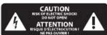
Controls
text_image
ATHENS TurbosoundC11 LCD SCREEN displays the current DSP module and parameter settings.
2 SETUP button steps through parameters within DSP processing modules.
(1) PROCESS button steps through the DSP processing modules.
(4) AUDIO LINK XLR connector provides an un-processed copy of the AUDIO INPUT signal.
(5) AUDIO INPUT combo jack accepts input signals using XLR, balanced N° TRS or unbalanced N° TS connectors.
POWER switch turns the unit on and off.
[7] AC INPUT accepts power connections from power cables fitted with Neutrik powerCON twist-locking connectors.
① ENCODER KNOB toggles between Graphic and Edit modes (when pressed) and changes parameter values (when rotated).
[5] EXIT button returns to the top-level DSP screen when pressed.
ENTER button saves changes and deactivates Edit mode when pressed.
ULTRANET THRU sends out unprocessed digital audio from the ULTRANET IN connector to additional ULTRANET-equipped devices.
USB connection enables firmware updates and remote control over parameters via computer. Please visit turbosound.com to download DSP control software for your computer.
ULTRANET IN RJ45/Neutrik etherCON jack for connection to additional ULTRANET-equipped devices.
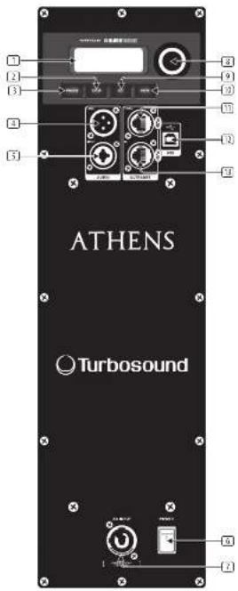
Networking capability
All TCS-AN powered loudspeakers offer remote control via USB. The USB connection allows the user to configure and monitor all DSP parameters using dedicated software for PC.
The DSP firmware can also be updated via the USB connection. Visit turbosound.com for the latest firmware version.
TCS-AN speakers also offer proprietary ULTRANET networking capabilities through the ULTRANET IN and ULTRANET THRU connections using CATS cables with RJAS connectors. ULTRANET allows the user to transmit unidirectionally up to 16 independent channels of 24-bit audio throughout the TCS-AN system, as well as other ULTRANET-equipped devices such as digital mixers and personal monitor systems. Up to 7 devices can be connected in series on a single ULTRANET cable.
flowchart
graph TD
    A["MDAE MS2"] --> B["ATENS"]
    B --> C["Turbosound"]
    C --> D["ATENS"]
    D --> E["Turbosound"]
    E --> F["ATENS"]
    F --> G["Turbosound"]
    G --> H["ATENS"]
    H --> I["Turbosound"]
    I --> J["ATENS"]
    J --> K["Turbosound"]
    K --> L["ATENS"]
    L --> M["Turbosound"]
    M --> N["ATENS"]
    N --> O["Turbosound"]
    O --> P["ATENS"]
    P --> Q["Turbosound"]
    Q --> R["ATENS"]
    R --> S["Turbosound"]
    S --> T["ATENS"]
    T --> U["Turbosound"]
    U --> V["ATENS"]
    V --> W["Turbosound"]
    W --> X["ATENS"]
    X --> Y["Turbosound"]
| Fullrange Subwoofer Function | ||||
| POSITION | Free | For positioning the speaker in free suspension or ground stacked away from walls. | ||
| Wall | Floor | For positioning the speaker on or not to a wall, or on the floor (subwoofer) | ||
| Ceiling | Wall | For positioning the speaker over the ceiling and wall, or front and wall isubwoofer | ||
| Corner Corner | For positioning the speaker in a corner next to the ceiling (fixed install) or in a corner on the floor (subwoofer) | |||
| Screenion update. | DELAY | Delay | Delay | Adjusts the amount of delay (max 300 msec = 103 m or 138 feet). |
| Unit | Unit | Selects between them, meters and feet. | ||
| LIMIT LIMITER | Limit Limit | Adjust the limit threshold for the input signal from OFF-up to 30 dBf. This threshold adjustment allows you to set time output power which is below the loudspeaker system's rated into output. | ||
| LOAD START SWITCH | SETUP(page 2) | Version Version Displays the installed firmware version. | ||
| LOAD SWITCH | 1, 20, 1, 20. | To load a specific preset, turn the encoder to select the desired preset 'number', and then press rather than ENTER button or the encoder. When asked for content press the encoder again or ENTER to abort. | ||
| SAVE SWITCH | 1, 20, 1, 20. | To save a preset choose the respective preset due and press ENTER or the encoder. | ||
| Sub Menu | Save Preset Save Preset | Name the preset by choosing the character with the encoder and pressing to confirm each character. When finished, press the ENTER button to save the preset. | ||
| SOLO SWITCHLOCK SWITCH | Contrast | Contrast | Adjust LCD panel contrast. The default contrast value is 15. | |
| ATHENS | Screen Screen | One LCD screen saw (default) turns on automatically after approve, 2 minutes. OFF- LCD turns off automatically after approve, 5 minutes. | ||
| SUB MENU | Lock | Lock | Lock the device and create a password by choosing the password characters with the encoder and pressing to confirm each character. After finished press the ENTER button, unlock the device by entering the password or according the unit via USB to a PC running proprietary remote software. The software does not require a password. | |
| DOWN MENU | Warning Warning | In one of overrunning, an alert appears on the LCD screen, and the amplifier will shut down until the unit costs. | ||
LCD Graphic Indicators
To help the user immediately recognize that a parameter has been selected and changed from the initial default setting, the parameter's related text on the top-level screen will invert and change to black text on a white background. As an example, the following screenshots show how the text for the EQ function changes when the TCS-AN default EQ setting has been changed:

This indicator function occurs only on the main DSP menu level and works for all DSP-related functions, except for the LOAD, SAVE and SETUP sub-sections on the second page of the top-level SETUP menu.
Mounting and Fixing
The table below summarises the rigging parts or kits required for various applications, and some examples of the possible rigging options are illustrated.
TCS-AH series cabinets are designed with multiple internal rigging points to suit many possible mounting methods in permanent installations. All cabinets can be simply suspended using optional MB or MTR shoulder eyebrows coupled to the internal rigging points provided. Remove the appropriate countersunk screws and replace them with eyebrows, which must have a thread length of at least 18mm. Use the rear rigging point to single the cabinet for optimum room coverage. Cabinets may be hung upside down if required. Turbosound WB-55 and CR-55 wall and ceiling brackets are optimally available for TCS-AH series cabinets, and these are also compatible with industry standard wall and ceiling brackets which use 50 mm x 60 mm hole spacing.
| Model | Wall | Ceiling | Downfill | Array Kit | Eyebulls |
| TCS122 W8-55 CB-55 | TCS122/PTCS-F61TCS-F62 | B4-10-40 | |||
| TCS152 W8-55 CB-55 | TCS152/PTCS-F61TCS-F62 | B4-10-40 | |||
| TCS1158 | TCS115-PTCS-F63 | B4-10-40 | |||
| TCS Subscaler 1B-10-40 |
Some typical examples of the possible rigging options are shown here:
natural_image
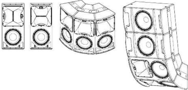
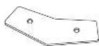
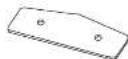
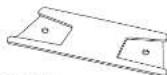
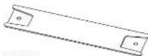
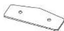
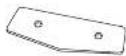
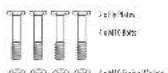
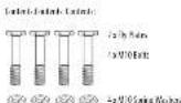
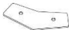
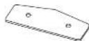
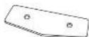
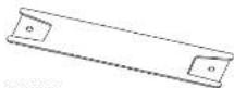
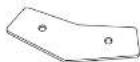
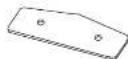
Technical line drawings of three different speaker housing designs (no text or symbols)TCS-AN Series Flying Components

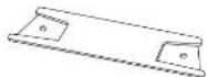
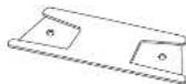
Wall and Ceiling Brackets
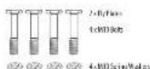
To install a loudspeaker using Turbosound wall and ceiling brackets, first separate the brackets into their wall/ceiling plate and speaker plate component parts. Remove the countersunk bolts on the rear panel of the cabinet. Attach the speaker plate to the cabinet with the bolts supplied. Fix the wall/ceiling plate in the venue using appropriate fixings (not supplied). Lift the loudspeaker on to the wall plate and re-assemble the bracket parts, adjust the vertical angle and tighten all bolts.
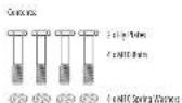
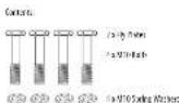
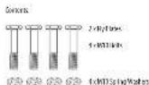
Loudspeaker Arrays and Clusters
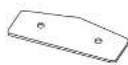
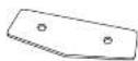
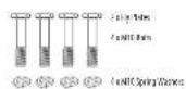
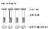
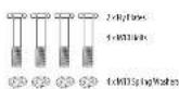
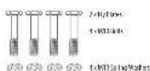
An array of two or more cabinets requires the use of kits of flyplates and inter-cabinet couplers, which are fixed to the cabinet sides through the MTD rigging points and assembled together in a 'daisy chain' fashion to build up the required array. For all loudspeaker arrays consisting of two or more cabinets:
The number of inter cabinet coupler kits required - the number of boxes - 1, The number of flyplate kits required - the number of boxes.
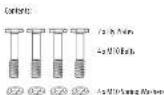
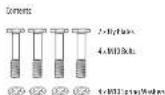
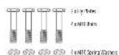
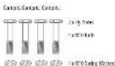
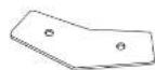
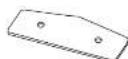
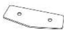
Illustrated here are the components parts available for TCS cabinets.
TCS152-IP(MII)
B, Flax B1 K1 TCS152
7CS122-P-3W1
R/Flex-R/Kr7CS122

© © © © 2: NIO Bokwesen

□ □ □ □ /sV1086388
10 10 10 10 10

TCS-RCT/AM
with Correct Groups B for TCS12c or TCS152
Consors: 2 cEX
125-35(###)
Into: Cai#r#Coup# 19.0x7251158
Contents 1:10C
TCB2 (HK)
Inter-Channel CounterFilter (CS12) or (CS13)
Generic - 1x10

B 1140
Erbcl V100 mm
Color: 12Fptd
Suspending with Eyebolts
TCS-MN cabinets can be suspended using optional eyebolts coupled to the internal rigging points provided on the top, bottom and sides and back. The simplest method is to use the two rigging points on the top and a single pull-back rigging point in the centre of the rear panel.
Remove the appropriate countersunk screws and replace them with shoulder eyebrows, which must have a thread length of at least 18 mm. Use the rear rigging point to angle the cabinet for optimum mom coverage. Cabinets may be hung upside down if required.
IMPORTANT NOTE FOR ALL INSTALLATION METHODS: The mounting of a permanently installed sound system may be dangerous unless undertaken by qualified personnel with the required experience and certification to perform the necessary tasks. Walls, floors or ceilings must be capable of safety and securely supporting the actual load. The mounting accessory used must be safely and securely fixed both to the loudspeaker and to the wall, floor or ceiling.
When mounting rigging components on walls, floors or ceilings, ensure that all fixings and fasteners used are of an appropriate site and load rating. Wall and ceiling claddings, and the construction and composition of walls and ceilings, all need to be taken into account when determining whether a particular fixing arrangement can be safely employed for a particular load. Cavity plugs or other specialist fixings, if required, must be of an appropriate type, and must be fitted and used in accordance with the maker's instructions.
The operation of your speaker cabinet as part of a flown system, if installed incorrectly and improperly, can potentially expose persons to serious health risks and even death. In addition, please ensure that electrical, mechanical and acoustic considerations are discussed with qualified and certified (by local state or national authorities) personnel prior to any installation or flying.
Make sure that speaker cabinets are set up and flown by qualified and certified personnel only, using dedicated equipment and original parts and components delivered with the unit. If any parts or components are missing please contact your Dealer before attempting to set up the system.
Be sure to observe the local, state and other safety regulations applicable in your country. Music Tribe, including the Music Tribe companies listed on the enclosed "Service Information Sheet", assumes no liability for any damage or personal injury resulting from improper use, installation or operation of the product. Regular checks must be conducted by qualified personnel to ensure that the system remains in a secure and stable condition. Make sure that, where the speaker is flown, the area underneath the speaker is free of human traffic. Do not fly the speaker in areas that can be entered or used by members of the public.
Speakers create a magnetic field, even if not in operation. Therefore, please keep all materials that can be affected by such fields (discs, computers, monitors, etc) at a safe distance. A safe distance is usually between 1 and 2 metres.
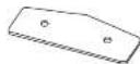
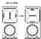
Rotating the HF horn pattern
The high frequency hom in all TCS122 and TCS152 models can be rotated through 90° in order to swap the horizontal and vertical dispersion patterns, particularly useful when assembling clusters or for example to retain the original dispersion when the cabinet is installed in a horizontal orientation.
- Place the cabinet on its back on a suitable work surface.
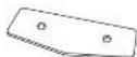
- Remove the 10 post-drive screws that hold the grille in place and set the grille aside (Fig 1).
- Remove and disconnect the bass driver (fig 2) to access the compression driver retaining brace, making a note of the bass driver polarity for later reconnection.
- Reach in through the bass driver cavity and loosen the two wing nuts securing the compression driver retaining brace (Fig 3).
- Remove the horn fixing screws that secure the horn to the enclosure and lift out the horn and compression driver assembly (fig 4). (If required for servicing or replacement, disconnect the cables from the compression driver, making a note of the polarity for later reconnection.)
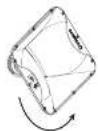
- Rotate the nom to achieve the desired coverage pattern [fig 5].
- Re-assemble the cabinet and drivers by reversing steps 1-5.
- If the compression driver cables have been disconnected, reconnect the cables while observing the correct polarity (white cable to the -ve terminal, black cable to the -ve terminal).
- Place the horn and compression driver back into the cabinet, making sure that the driver cables pass underneath the compression driver retainer and that the compression driver fits squarely back into the retaining brace.
- Tighten the wing nuts back onto the compression driver retaining brace [fig 3].
- Replace the horn fixing screws and tighten to secure the horn back into the enclosure (Fig 4).
- Reconnect the bass driver cables, observing the correct polarity (red cable to the +ve terminal, blue cable to the -ve terminal).
- Check all components and confirm the horn orientation is correct [fig 6].
- Replace the grille (fig 1) and phase check the cabinet before use.

kg.1
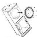
Fig.2
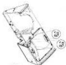
图3
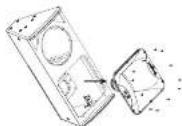
图2-15-10.6
text_image
ATHENS Turbosoundnatural_image
Technical line drawings of four different speaker housing configurations (no text or symbols)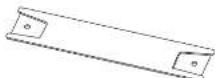
12.30-4 [6]C
(b) 4-dna for X=151
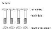
⑤ ⑥ ⑦ ⑧ 4:NICRA Mo#a
① ② ③ ④ ⑤
⑤ ⑥ ⑤ ⑥ 4xMD/Fat/Walers
IC-PC10K
rbc-camC:coaRtBcIcIIS2/cclRS
(###) - 7.6K
75-43-MH
In-line data (appr) for 2019
Somatic Jol.
TCS B214K
Intra Gau et Goula B1 for TCS122 or TCS152
(crem: 3 eK)

B 114
E,abc(10)240mm
(cubcl: 1cylcbl)
text_image
ATHENS Turbosoundnatural_image
Technical line drawings of a multi-tiered speaker tower assembly (no text or symbols)
© © © 4: NICOLI Market
20 20 20 20 427014 MoMn

© © © © 4-MD/10/Sales
TCS RELIAR
In the case of the TCS12 or TCS15
Consors: 2 cEX

72 PS(MH)
Min (Max Cap) for 725.193
Gorax 1-IX

TC-49210M
info-Casal-Code#10 for IT 527 or IT 535
(see www.163)

E-11-1
Lybe173b 4mm
Linde: 1cl,yeed
text_image
ATHENS Turbosoundflowchart
graph TD
    MD45DL16["MD45 DL16"] --> MD45MS2["MD45 MS2"]
    MD45MS2 --> ATHENS1["ATHENS"]
    MD45MS2 --> ATHENS2["ATHENS"]
    MD45MS2 --> ATHENS3["ATHENS"]
    MD45MS2 --> ATHENS4["ATHENS"]
    ATHENS1 --> Turbosound1["Turbosound"]
    ATHENS2 --> Turbosound2["Turbosound"]
    ATHENS3 --> Turbosound3["Turbosound"]
    ATHENS4 --> Turbosound4["Turbosound"]
natural_image
Technical line drawings of a multi-tiered speaker tower assembly (no text or symbols)
TCR1/AR
Inter-Correct Cooler H for TGT22 or TGT32
Cofactors: 2x100.
12 B3/MH
Inter-Chine (exp) 12/159

TCS-02 (A)
Intra-Caust-Guolar B1 for TCS123 or TCS152
Convers. To Beclit

E_1abc (V) Do 40mm
Census:
text_image
ATHENS Turbosoundnatural_image
Technical line drawings of four different speaker housing configurations (no text or symbols)Componentes Voadores Série TCS-AN
Suportes de parede e teto
7CS122 FP 3W-1
By Fire Bt for CS122
TCS115 47 (AM)
By: 0.0283 (CS115)
4: NID-114 Market
© © © © 12/01/14 Mod.
4. KONI WOEN

TCS-RCI/MK
Inter-Channel Computer Error for TCS12.0 to TCS32
Contents: 2 eKL

123 83 (MHz)
Inter-Cabinet Coupler (MHz) 1251159
[cm] = 2.012

TCS-02 (A)
Intra-Caixt-Goula B for TCS12 or TCS15
Covers 1 dX

14-11-4
E,abc(1/2)0.40mm
Cenon: 1cE,abc
text_image
ATHENS Turbosoundflowchart
graph TD
    A["MDA3/M32"] --> B["ATHENS"]
    B --> C["Turbosound"]
    C --> D["ATHENS"]
    D --> E["Turbosound"]
    E --> F["ATHENS"]
    F --> G["Turbosound"]
    G --> H["ATHENS"]
    H --> I["Turbosound"]
    I --> J["ATHENS"]
    J --> K["Turbosound"]
    K --> L["ATHENS"]
    L --> M["Turbosound"]
    M --> N["ATHENS"]
    N --> O["Turbosound"]
    O --> P["ATHENS"]
    P --> Q["Turbosound"]
    Q --> R["ATHENS"]
    R --> S["Turbosound"]
    S --> T["ATHENS"]
    T --> U["Turbosound"]
    U --> V["ATHENS"]
    V --> W["Turbosound"]
    W --> X["ATHENS"]
    X --> Y["Turbosound"]
natural_image
Technical line drawings of four different speaker housing configurations (no text or symbols)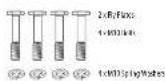
© © © © 4-MD/10/Sales

TCS RELIAR
In the case of the TCS12 or TCS15
Consors: 2 cEX
725 PB3(MH)
Min (Lead Copper) for 725.193
Conex 161X
TC-4921/M
mio-Canul-Lozzer B1 for IT (327 or 350)
(see next.) eKI

E3-11-7
Lybe1/25h 4mm
Linde: Telpect
text_image
ATHENS Turbosoundnatural_image
Technical line drawings of a multi-tiered speaker tower assembly (no text or symbols)
7CS122 FP 3W-1
By Fire Bt for CS122

TCS115 47 (AM)
By: 0.0283 (CS115)
4: NID-114 Market
© © © © 12/01/14 Mod.
4.001 W/500
TCS-RC1/AR
inter-Context Similar to for TCS12c: TCS12
Contents: 3 eK1
725 83 (MHI
Inter-Calvin-Couple) Ref: 725-159
Icelerich - 3 (01)
105402 104
In a Carad Goula B for TCS122 or TCS132
Goula B 2100

14-15-0
Ejede IV 1024(###)
C##t##. 1#Ejede#.
text_image
ATHENS Turbosoundnatural_image
Technical line drawing of a multi-tiered mechanical housing or enclosure with circular components (no text or symbols)Flygkomponenter i TCS-AN-serien
Vägg- och takfästen
© © © © 2: NIO Bokwesen
□ □ □ □ /sV108636

10 10 10 10 10
TCS-RCT/AM
Incr. Caneet Goula B for TCS12c or TCS152
Comms. 2 dEX
125-35(###)
Into: Cai#r#e Coupie 19.04-7251158
Contents 1-10C
TCB2 (HK)
Inter-Channel CounterFilter (CS12) or (CS13)
Generic - 1x10

B 1140
Erbcl V100 mm
Color: 12Fptd
text_image
ATHENS TurbosoundSubsolvency 1CS 18-040
natural_image
Technical line drawing of a multi-tiered mechanical housing or enclosure with circular components (no text or symbols)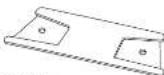
7CS122 FP 3W-1
By Fire Bt for CS122
TCS115 47 (AM)
By: 062837 (CS115)
4: NID-114 Market
© © © © 12/01/14 Mod.
4.001 W/500
TCS-RCI/MK
Inter-Carrel Complex I for TCS22 or TCS32
Contents: 1 eKL
123 83 (MHz)
Inter-Cabinet Couple: 1231159
Contents: 2 e10
TCS-02 [M]
Intra-Caustal Cerebrin for TCS12c or TCS152
Cerebrin 2 dX

14-11-4
E,abc(1/2)0.40mm
Cenon: 1cE,abc
Technical Specifications
TCS122/64-AN (-WH) TCS122/94-AN (-WH) TCS122/96-AN (-WH) TCS152/64-AN (-WH)
| System | ||||
| Frequency response | 50 Hz - 18 kHz ± 3 dB45 Hz - 20 kHz - 10 dB | 50 Hz - 18 kHz ± 3 dB45 Hz - 20 kHz - 10 dB | 50 Hz - 18 kHz ± 3 dB45 Hz - 20 kHz - 10 dB | 41 Hz - 18 kHz ± 3 dB35 Hz - 20 kHz - 10 dB |
| Nominal dispersion | 62" II x 40V @ 6 dB points, rotatable | 90" II x 40V @ 6 dB points, rotatable | 90" II x 60V @ 6 dB points, rotatable | 60" II x 40V @ 6 dB points, rotatable |
| Minimum S/P, 131 dB peak 131 dB peak 131 dB peak 133 dB peak | ||||
| Crossover type Active Active Active | ||||
| Transducers | 1 x 12" (312 mm)LF Driver1 x 1.4" (36 mm)HF compression driver | 1 x 12" (312 mm)LF Driver1 x 1.4" (36 mm)HF compression driver | 1 x 12" (312 mm)LF Driver1 x 1.4" (36 mm)HF compression driver | 1 x 15" (394 mm) LF Driver1 x 1.4" (36 mm)HF compression driver |
| Limiter | Independent HF, LF, peak and rms | Independent HF, LF, peak and rms | Independent HF, LF, peak and rms | Independent HF, LF, peak and rms |
| Amplifier | ||||
| Maximum output power * 2500 V/2500 V/2500 V/2500 V# | ||||
| Type Class-D Class-D Class-D Class-D | ||||
| Protection | Short circuit, thermal | Short circuit, thermal | Short circuit, thermal | Short circuit, thermal |
| Connectors | ||||
| Input/Link | 1 x Combo Jack/XLR, 1 x ALR | 1 x Combo Jack/XLR, 1 x ALR | 1 x Combo Jack/XLR, 1 x ALR | 1 x Combo Jack/XLR 1 x XLR |
| Sensitivity | +4 dBu or +14 dBu software switchable | +4 dBu or +14 dBu software switchable | +4 dBu or +14 dBu software switchable | +4 dBu or +14 dBu software switchable |
| Input impedance | 40 kΩ balanced | 40 kΩ balanced | 40 kΩ balanced | 40 kΩ balanced |
| Maximum input level | +22 dBu | +22 dBu | +22 dBu | -22 dBu |
| Ultralent input/Link | 2 x R45 | 2 x R45 | 2 x R45 | 2 x R45 |
| Matrix Supply | Neutrik powerCOH 20A | Neutrik powerCOH 20A | Neutrik powerCOH 20A | Neutrik powerCOH 20A |
| Controls | ||||
| DSP | Rotary push encoder and level controlButtons for Process, Setup,Lext, Linter | Rotary push encoder and level controlButtons for Process, Setup,Lext, Linter | Rotary push encoder and level controlButtons for Process, Setup,Lext, Linter | Rotary push encoder and level controlButtons for Process, Setup,Lext, Linter |
| User DSP Functions | ||||
| Factory EQ Peaks | Positioning, Sound mode, FBQ | Positioning, Sound mode, FBQ | Positioning, Sound mode, FBQ | Positioning, Sound mode, FBQ |
| Display | LCD 128 x 32, blue, backlit | LCD 128 x 32, blue, backlit | LCD 128 x 32, blue, backlit | LCD 128 x 32, blue, backlit |
| Delay | 0 - 300 ms | 0 - 300 ms | 0 - 300 ms | 0 - 300 ms |
| Equilisation | High and low sheathing EQ2 x parameter EQ | High and low sheathing EQ2 x parameter EQ | High and low sheathing EQ2 x parameter EQ | High and low sheathing EQ2 x parameter EQ |
| Limiter | Zero attack input limiter | Zero attack input limiter | Zero attack input limiter | Zero attack input limiter |
| Presets | 20 total presets,19 user-definable | 20 total presets,19 user-definable | 25 total presets,19 user-definable | 20 total presets,19 user-definable |
| Crossover | High Pass L-R 24 dB/ocst | High Pass L-R 24 dB/ocst | High Pass L-R 24 dB/ocst | High Pass L-R 24 dB/ocst |
| Protection | Lock-out function for all settings | Lock-out function for all settings | Lock-out function for all settings | Lock-out function for all settings |
Quick Start Guide 85
TCS122/64-AN (-WH) TCS122/94-AN (-WH) TCS122/96-AN (-WH) TCS152/64-AN (-WH)
| Ultrane Digital Network | ||||
| Digital processing | ||||
| A/O conversion | 24-bit, 14.1/18 kHz sample rate | 24-bit, 14.1/18 kHz sample rate | 24-bit, 14.1/18 kHz sample rate | 24-bit, 14.1/18 kHz sample rate |
| Converter type | 24-bit, delta sigma | 24-bit, delta sigma | 24-bit, delta sigma | 24-bit, delta sigma |
| System | ||||
| Signal | 16 channels | 16 channels | 16 channels | 16 channels |
| Latency | < 0.9 ms | < 0.9 ms | < 0.9 ms | < 0.5 ms |
| Frequency response | 20 Hz to 20 kHz (+0 / -3 dB) | 20 Hz to 25 kHz (+0 / -3 dB) | 20 Hz to 20 kHz (+0 / -3 dB) | 20 Hz to 20 kHz (+0 / -3 dB) |
| Dynamic range | typical 92 dB | typical 92 dB | typical 92 dB | typical 92 dB |
| Cabling | ||||
| Cables | Shielded CATS | Shielded CATS | Shielded CATS | Shielded CATS |
| Cable length | max. 246 ft / 75 m recommended | max. 246 ft / 75 m recommended | max. 246 ft / 75 m recommended | max. 246 ft / 75 m recommended |
| Power Supply | ||||
| Power consumption | 90 W / kg / max power | 90 W / kg / max power | 90 W / kg / max power | 90 W / kg / max power |
| Voltage (uses) | ||||
| USA / Canada | 120 V~, 60 Hz(1 T5 A H 250 V) | 120 V~, 60 Hz(1 T5 A H 250 V) | 120 V~, 60 Hz(1 T5 A H 250 V) | 120 V~, 60 Hz(1 T5 A H 250 V) |
| UK / Australia / Europe | 220-240 V~, 50/60 Hz(T 10 A H 250 V) | 220-240 V~, 50/60 Hz(T 10 A H 250 V) | 220-240 V~, 50/60 Hz(T 10 A H 250 V) | 220-240 V~, 50/60 Hz(T 10 A H 250 V) |
| Korea / China | 220-240 V~, 50/60 Hz(T 10 A H 250 V) | 220-240 V~, 50/60 Hz(T 10 A H 250 V) | 220-240 V~, 50/60 Hz(T 10 A H 250 V) | 220-240 V~, 50/60 Hz(T 10 A H 250 V) |
| Japan | 120 V~, 50/60 Hz(T 15 A H 250 V) | 120 V~, 50/60 Hz(T 15 A H 250 V) | 120 V~, 50/60 Hz(T 15 A H 250 V) | 120 V~, 50/60 Hz(T 15 A H 250 V) |
| Endoore | ||||
| Dimensions HDD | 834 x 399 x 425 mm(32.8 x 15.7 x 16.7") | 834 x 399 x 425 mm(32.8 x 15.7 x 16.7") | 834 x 399 x 425 mm(32.8 x 15.7 x 16.7") | 834 x 423 x 451 mm(32.8 x 16.6 x 17.8") |
| Net weight | 27.8 kg (61.2 lbs) | 27.8 kg (61.2 lbs) | 27.8 kg (61.2 lbs) | 30.6 kg (67.3 lbs) |
| Construction | 15 mm (1" inch plywood | 15 mm (2" & 8 inch plywood | 15 mm (2" & 8 inch plywood | 15 mm (3" inch plywood |
| Finish | Semi matt black paint(white optional) | Semi matt black paint(white optional) | Semi matt black paint(white optional) | Semi matt black paint(white optional) |
| Grille | Powder coated perforated steel | Powder coated perforated steel | Powder coated perforated steel | Powder coated perforated steel |
| Flying hardware | M10 x 9, M8 x 8 points | M10 x 9, M8 x 8 points | M10 x 9, M8 x 8 points | M10 x 9, M8 x 8 points |
| Accessories | ||||
| TCS122, FP (1/4W) Fly plate kit for TCS122 | TCS122, FP (1/4W) Fly plate kit for TCS122 | TCS122, FP (1/4W) Fly plate kit for TCS122 | TCS152, FP (1/4W) Fly plate kit for TCS152 | |
| TCS-FKI (1/4W) Inter-cabinetcoupler kit for TCS122 or TCS152 | TCS-FKI (1/4W) Inter-cabinetcoupler kit for TCS122 or TCS152 | TCS-FKI (1/4W) Inter-cabinetcoupler kit for TCS122 or TCS152 | TCS-FKI (1/4W) Inter-cabinetcoupler kit for TCS122 or TCS152 | |
| TCS FKI (1/4W) Inter-cabinetcoupler kit for TCS115B withTCS122 or TCS152 | TCS FKI (1/4W) Inter-cabinetcoupler kit for TCS115B withTCS122 or TCS152 | TCS FKI (1/4W) Inter-cabinetcoupler kit for TCS115B withTCS122 or TCS152 | TCS FKI (1/4W) Inter-cabinetcoupler kit for TCS115B withTCS 122 or TCS152 | |
Technical Specifications
| System | ||||
| Frequency response | 41 Hz - 18 kHz ± 1 dB35 Hz - 20 kHz - 10 dB | 41 Hz - 18 kHz ± 1 dB15 Hz - 20 kHz - 10 dB | 45 Hz - 150 Hz ± 1 dB40 Hz - 200 Hz - 10 dB | 33 Hz - 200 Hz ± 1 dB27 Hz - 200 Hz - 10 dB |
| Nominal dispersion | 92" H x 40" V @ 6 dB points, rotatable | 90" H x 60" V @ 6 dB points, rotatable | Pair Space Hall Space | |
| Minimum SPL 133 dB peak 133 dB peak 141 dB peak | ||||
| Crossover type Active Active Active Active | ||||
| Transducers | 1 x 15" (394 mm) LF Driver1 x 1.4" (36 mm)HF compression driver | 1 x 15" (394 mm) LF Driver1 x 1.4" (36 mm)HF compression driver | 1 x 15" (387 mm) LF driver/ | 2 x 16" (460 mm) LF driver/ |
| Limiter | Independent HF, LF, peak and rms | Independent HF, LF, peak and rms | Peak and rms | Peak and rms |
| Amplifier | ||||
| Minimum output power* | 2500 Ω | 2500 Ω | 3000 Ω | 6000 Ω |
| Type | Class-D | Class-D | Class-D | Class-D |
| Protection | Short circuit, thermal | Short circuit, thermal | Short circuit, thermal | Short circuit, thermal |
| Connectors | ||||
| Input/link | 1 x Combo Jack/XLR 1 x XLR | 1 x Combo Jack/XLR 1 x XLR | 1 x Combo Jack/XLR 1 x XLR | 1 x Combo Jack/XLR 1 x XLR |
| Sensitivity | +4 dBu or +14 dBu software switchable | +4 dBu or +14 dBu software switchable | +4 dBu or +14 dBu software switchable | +4 dBu or +14 dBu software switchable |
| Input impedance | 40 kΩ balanced | 40 kΩ balanced | 40 kΩ balanced | 40 kΩ balanced |
| Maximum input level | +22 dBu | +22 dBu | +22 dBu | +22 dBu |
| Ultranet input/link | 2 x R45 | 2 x R45 | 2 x R45 | 2 x R45 |
| Maine Supply | Neutlink powerCON 20A | Neutlink powerCON 20A | Neutlink powerCON 20A | Neutlink powerCON 20A |
| Controls | ||||
| DSP | Rotary push-encoder and level controlButtons for Process, Setup,OLT, Enter | Rotary push-encoder and level controlButtons for Process, Setup,OLT, Enter | Rotary push-encoder and level controlButtons for Process, Setup,OLT, Enter | Rotary push-encoder and level controlButtons for Process, Setup,OLT, Enter |
| User DSP Functions | ||||
| Factory EQ Presets | Positioning, Sound mode, FBQ | Positioning, Sound mode, FBQ | Positioning, Sound mode | Positioning, Sound mode |
| Display | LCD 128 x 32, blue, backlit | LCD 128 x 32, blue, backlit | LCD 128 x 32, blue, backlit | LCD 128 x 32, blue, backlit |
| Delay | 0 - 300 ms 0 - 300 ms 0 - 300 ms 0 - 300 ms 0 - 300 ms 0 - 300 ms 0 - 300 ms 0 - 300 ms 0 - 300 ms 0 - 300 ms 0 - 300 ms 0 - 300 ms 0 - 300 ms 0 - 100 ms 0 - 100 ms 0 - 100 ms 0 - 100 ms 0 - 100 ms 0 - 100 ms 0 - 100 ms 0 - 100 ms 0 - 100 ms 0 - 100 ms 0 - 100 ms 0 - 100 ms 0 - 100 ms | |||
| Equalisation | High and low shelving EQ2 x parametric EQ | High and low shelving EQ2 x parametric EQ | High and low shelving EQ2 x parametric EQ | High and low shelving EQ2 x parametric EQ |
| Limiter | Zero attack input limiter | Zero attack input limiter | Zero attack input limiter | Zero attack input limiter |
| Presets | 20 total presets,19 user-detainable | 20 total presets,19 user-detainable | 25 total presets,19 user-detainable | 25 total presets,19 user-detainable |
| Crossover | High Pass L R 24 effect | High Pass L R 24 effect | Low Pass L R 24 effect | Low Pass L R 24 effect |
| Protection | Lock-out function for all settings | Lock-out function for all settings | Lock-out function for all settings | Lock-out function for all settings |
Quick Start Guide 87
| Ultraneet Digital Network | ||||
| Digital processing | ||||
| 4-D outputson | 24-bit, 64.1/48 kHz sample rate | 24-bit, 64.1/48 kHz sample rate | 24-bit, 64.1/48 kHz sample rate | 24-bit, 64.1/48 kHz sample rate |
| Converter type | 24-bit, delta-sigma | 24-bit, delta-sigma | 24-bit, delta-sigma | 24-bit, delta-sigma |
| System | ||||
| Signal | 16 channels | 16 channels | 16 channels | 16 channels |
| Latency | <0.9 ms | <0.9 ms | <0.9 ms | <0.5 ms |
| Frequency response | 20 Hz to 20 kHz (+0.1 -3 dB) | 25 Hz to 20 kHz (+0.1 -3 dB) | 20 Hz to 25 kHz (-0.1 -3 dB) | 20 Hz to 25 kHz (-0.1 -3 dB) |
| Dynamic range | typical 92 dB | typical 92 dB | typical 92 dB | typical 92 dB |
| Cabling | ||||
| Cables | Shielded CATS | Shielded CATS | Shielded CATS | Shielded CATS |
| Cable length | max. 246 ft / 75 m recommended | max. 246 ft / 75 m recommended | max. 246 ft / 75 m recommended | max. 246 ft / 75 m recommended |
| Power Supply | ||||
| Power consumption | 90 W @ 4 max power 90 V @ | 7-max power | 100 V @ 7 max power | 350 W @ 5 max power |
| Voltage (uses) | ||||
| USA / Canada | 120 V ~ 60 Hz(T 15 A H 250 V) | 120 V ~ 60 Hz(T 15 A H 250 V) | 120 V ~ 60 Hz(T 15 A H 250 V) | 120 V ~ 60 Hz(T 15 A H 250 V) |
| UK / Australia / Europe | 220-240 V ~ 50/60 Hz(T 10 A H 250 V) | 220-240 V ~ 50/60 Hz(T 10 A H 250 V) | 220-240 V ~ 50/60 Hz(T 10 A H 250 V) | 220-240 V ~ 50/60 Hz(T 10 A H 250 V) |
| Korea / China | 220-240 V ~ 50/60 Hz(T 10 A H 250 V) | 220-240 V ~ 50/60 Hz(T 10 A H 250 V) | 220-240 V ~ 50/60 Hz(T 10 A H 250 V) | 220-240 V ~ 5O/60 Hz(T 10 A H 250 V) |
| Japan | 120V ~ 50/60 Hz(T 15 A H 250 V) | 100V ~ 50/60 Hz(T 15 A H 250 V) | 100V ~ 50/60 Hz(T 15 A H 250 V) | 100V ~ 50/60 Hz(T 15 A H 250 V) |
| Endurance | ||||
| Dimensions HDD | 834 x 473 x 451 mm(32.8 x 18.6 x 17.8") | 834 x 473 x 451 mm(32.8 x 18.6 x 17.8") | 834 x 469 x 452 mm(32.8 x 18.5 x 17.8") | 710 x 1130 x 230 mm(28 x 44.5 x 28.7") |
| Net weight | 30.6 kg (67.3 lbs) | 30.6 kg (67.3 lbs) | 34.5 kg (75.9 lbs) | 95.5 kg (210.1 lbs) |
| Construction | 15 mm (1" Pitch plywood) | 15 mm (1" 8-inch plywood) | 15 mm (6" 1" Birch plywood) | 18 mm (3" 1" Birch plywood) |
| Finish | Semi matt black paint(white optional) | Semi matt black paint(white optional) | Semi matt black paint(white optional) | Semi matt black paint(white optional) |
| Grille | Powder coated perforated steel | Powder coated perforated steel | Powder coated perforated steel | Powder coated perforated steel |
| Flying hardware | MTO x 0; MTO x 8 points | MTO x 0; MTO x 8 points | MTO x 8 | MTO x 8 |
| Accessories | ||||
| TCS152: FP (-) MVO Fly plate kit for TCS152 | TCS152: FP (-) MVO Fly plate kit for TCS152 | TCS115: FP (-) MVO Fly plate kit for TCS115B | ||
| TCS-FIO (-) MVO Inter-cabinetcoupler kit for TCS123 or TCS122 | TCS-FIO (-) MVO Inter-cabinetcoupler kit for TCS123 or TCS122 | TCS-FK2 (-) MVO Inter-cabinetcoupler kit for TCS115B with TCS122 or TCS122 | ||
| TCS-TK2 (-) MVO Inter-cabinetcoupler kit for TCS115B with TCS123 or TCS122 | TCS-TK2 (-) MVO Inter-cabinetcoupler kit for TCS113B with TCS122 or TCS122 | TCS-FK2 (-) MVO Inter-cabinetcoupler kit for TCS115B | ||
* independent of limiters and driver protection circuits
† Only qualified personnel are allowed to modify the AC-Main cord and to adhere to all applicable national standards.
Other important information

Important information
- Register online. Please register your new Music Tribe equipment right after you purchase it by visiting muscibe.com. Registering your purchase using our simple online form helps us to process your repair claims more quietly and efficiently. Also, read the terms and conditions of our warranty, if applicable.
- Malfunction, Should your Music Tribe Author and Reseller not be located in your vicinity, you may contact the Music Tribe Authorized Fulfill for your country listed under "Support" at musicitibe.com. Should your country not be listed, please check if your problem can be dealt with by our "Online Support" which may also be found under "Support" at musicitibe.com. Alternatively, please submit an online warranty claim at musicitibe.com BEFORE returning the product.
- Power Connections. Before plugging the unit into a power socket, please make sure you me using the correct mains voltage for your particular model. Equity fuses must be replaced with fuses of the same type and rating without exception.

Responsible Party Name: Music Tribe Commercial NV Inc.
Address: 5270 Procyon Street,
Las Vegas NV 89118,
United States
Phone Number: +1 702 800 8290
TCS-AN SERIES
This equipment has been tested and found to comply with the limits for a Class A digital device, pursuant to part 15 of the FCC Rules. These limits are designed to provide reasonable protection against harmful interference when the equipment is operated in a commercial environment. This equipment generates, uses, and can radiate radio frequency energy and, if not installed and used in accordance with the instruction manual, may cause harmful interference to radio communications. Operation of this equipment in a residential area is likely to cause harmful interference in which case the user will be required to correct the interference at his own expense.
This device complies with Part 15 of the FCC rules. Operation is subject to the
following two conditions:
(1) this device may not cause harmful interference, and
[2] this device must accept any interference received, including interference that may cause undesired operation.
Warning: Operation of this equipment in a residential environment could cause radio interference.
Important information:
Changes or modifications to the equipment not expressly approved by Music Tribe can void the user's authority to use the equipment.

Hereby, MUSIC Tribe declares that this product is in compliance with Directive 2014/35/EU, Directive 2014/30/EU, Directive 2011/65/EU and Amendment 2015/863/EU, Directive 2012/19/EU, Regulation 519/2012 REACH SVHC and Directive 1907/2006/EC.
Full text of EU DoC is available at https://community.musictribe.com/
EU Representative: Music Tribe Brands DK A/S
Address: In Spang Olsens Gade 17, DK - 8200arhus N, Denmark