EC7008 - Surveillance Camera ECCO - Free user manual and instructions
Find the device manual for free EC7008 ECCO in PDF.

| Product Type | Wireless Vehicle Surveillance Camera System |
| Brand | ECCO |
| Model | EC7008 (Monitor EC7008-WK, Camera EC2027-WC) |
| Display | 7 inches, resolution 800x3(RGB)x480, contrast 500:1, brightness 400 cd/m² |
| Camera | 1/3" CMOS sensor, 500 TV lines, IR night vision (0 Lux) |
| Monitor power supply | DC 10–32 V, max consumption 6 W |
| Camera power supply | 12–24 VDC (10–30 V), max consumption 250 mA (12 V) / 140 mA (24 V) |
| Number of cameras | Up to 4 (wireless) |
| Operating frequency | 2.4 GHz (2400–2483.5 MHz) |
| Transmission distance | 120 m (without obstacles) |
| Video compression | MPEG4 |
| Video formats | PAL (25 fps) / NTSC (30 fps) |
| Recording | On Micro SD card (max 128 GB), automatic overwriting |
| Main functions | Wireless pairing, camera switching, dual/quad display, image adjustments (brightness, contrast, hue), mirror/flip, audio, parking countdown, auto backlight |
| Maintenance and cleaning | Do not expose to water. Clean the screen with a soft dry cloth. Do not open the housing. |
| Safety | Installation by a professional. Grounding mandatory. 3 A fuse on positive line. Waterproof the connections. |
| Spare parts (references) | Camera EC2027-WC, monitor EC7008-WM, cable PCY-7008-WM, antenna ECANTE-R, base bracket MB01, sun visor AS7000SS |
| Warranty | 36 months limited (parts and labor) |
| Operating temperature | Monitor: -20 to +70 °C; Camera: -20 to +70 °C (storage -30 to +80 °C) |
| Standards | Compliant with FCC Part 15 |
Frequently Asked Questions - EC7008 ECCO
User questions about EC7008 ECCO
0 question about this device. Answer the ones you know or ask your own.
Ask a new question about this device
Download the instructions for your Surveillance Camera in PDF format for free! Find your manual EC7008 - ECCO and take your electronic device back in hand. On this page are published all the documents necessary for the use of your device. EC7008 by ECCO.
USER MANUAL EC7008 ECCO
Failure to install or use this product according to manufacturer's recommendations may result in property damage, serious bodily/personal injury, and/or death to you and those you are seeking to protect!

Do not install and/or operate this safety product unless you have read and understand the safety information contained
- Proper installation combined with operator training in the use, care, and maintenance of safety products are essential to ensure the safety of you and those you are trying to protect.
- Exercise caution when working with live electrical connections.
- This product must be properly grounded. Inadequate grounding and/or shorting of electrical connections can cause high current arcing, which can cause personal injury and/or severe vehicle damage, including fire.
- Proper placement and installation are vital to the performance of this safety product. Install this product so that the performance of the system is maximized and the controls are placed within convenient reach of the operator so that s/he can operate the system without losing eye contact with the roadway.
- It is the responsibility of the vehicle operator to ensure during use that all features of this product work correctly. In use, the vehicle operator should ensure the field-of-view of the camera/monitor is not blocked by vehicle components (i.e., open trunks or compartment doors), people, vehicles, or other obstructions.
- Never take the right-of-way for granted. It is your responsibility to be sure you can proceed safely before entering an intersection, driving against traffic, responding at a high rate of speed, walking on or around traffic lanes.
- This equipment is intended for use by authorized personnel only. The user is responsible for understanding and obeying all laws regarding safety products. Therefore, the user should check all applicable city, state, and federal laws and regulations. The manufacturer assumes no liability for any loss resulting from the use of this safety product.
Installation, Wiring and Function

Caution! When drilling into any vehicle surface, make sure that the area is free from any electrical wires, fuel lines,istry, etc. that could be damaged.
CAMERA SYSTEM MODEL EC7008-WK OPERATING INSTRUCTIONS:

WARNING!
- Please align the remote control with the remote signal receiver window to operate.
- Never disassemble the remote control or allow it to drop or get wet.
WIRING INSTRUCTIONS:
Important! Waterproof all connections whether inside or outside the vehicle by using sealant and wrapping with insulation tape. Wrap tape tightly, overlapping by one-half widths so there are no gaps.
Notes:
- Larger wires and tight connections will provide longer service life for components. For high current wires it is recommended that terminal blocks or soldered connections be used with shrink tubing to protect the connections. Do not use insulation displacement connectors (e.g., 3M Scotchlock type connectors)
- Route wiring using grommets and sealant when passing through compartment walls. Minimize the number of splices to reduce voltage drop. High ambient temperatures (e.g., under-hood) will significantly reduce the current carrying capacity of wires, fuses, and circuit breakers. All wiring should conform to the minimum wire size and other recommendations of the manufacturer and be protected from moving parts and hot surfaces. Looms, grommets, cable ties, and similar installation hardware should be used to anchor and protect all wiring.
- Fuses or circuit breakers should be located as close to the power takeoff points as possible and properly sized to protect the wiring and devices.
- Particular attention should be paid to the location and method of making electrical connections and splices to protect these points from corrosion and loss of conductivity.
- Ground termination should be only be made to substantial chassis components, preferably directly to the vehicle battery.
- Circuit breakers are very sensitive to high temperatures and will "false trip" when mounted in hot environments or operated close to their capacity.
The unit is designed for electrical systems from 12 to 24 VDC (10 to 30 VDC extremes). Wiring options are as follows in Figure 1:
All wiring should be a minimum of 26 AWG. A 3-amp fuse in the positive line for the monitor is required.
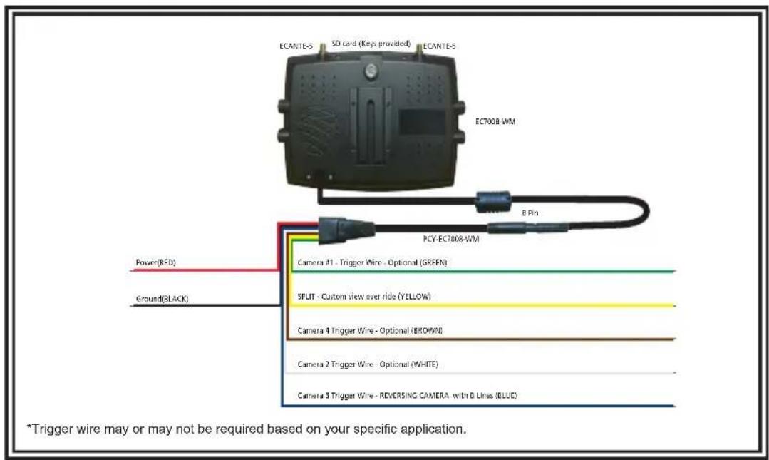
Figure 1

=no/low signal

= full signal and you are ready to go to next step
INSTALLATION INSTRUCTIONS:
RECOMMENDED TO BENCH TEST PRIOR TO INSTALL to establish placement/priority for cameras.
- Trim the solder tips to improve connections
- Install both antennas onto the monitor - twist on
- Connect the monitor power cord to the harness by lining up the notches to fully seat over the knob
- Power on the monitor by connecting the red to power and black to ground
- Monitor will default to Scan Mode with Camera 1
- Using the remote, SEL button on remote, choose Camera 1 for pairing
- DO NOT power on camera.
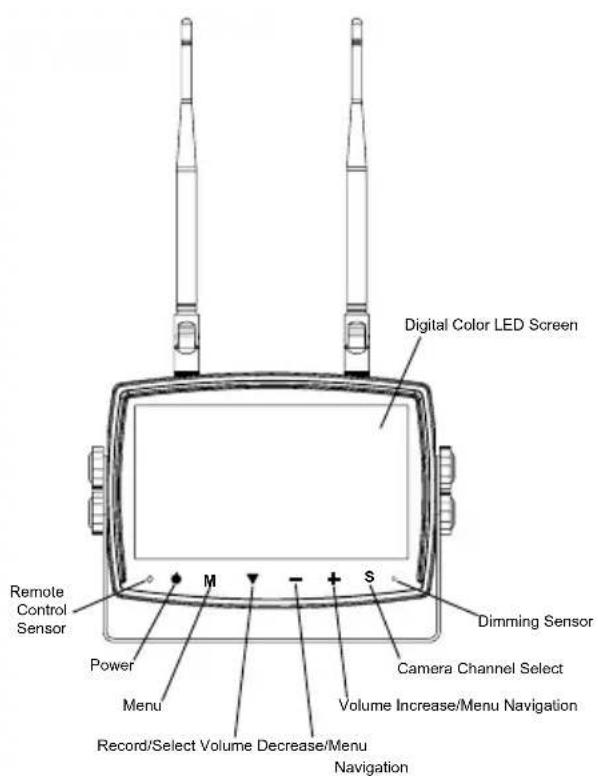
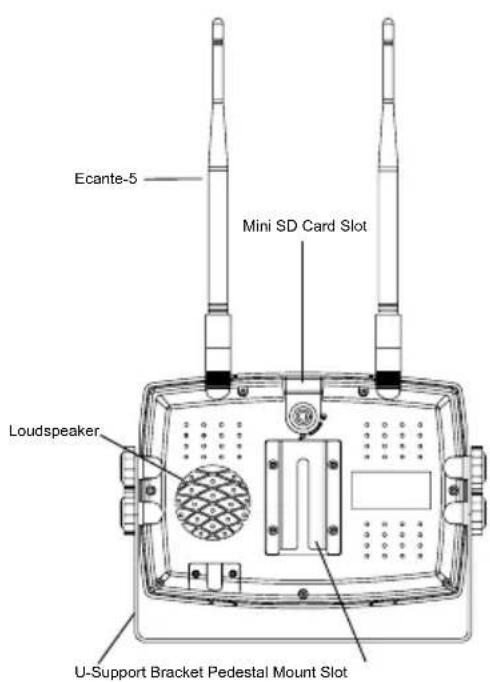
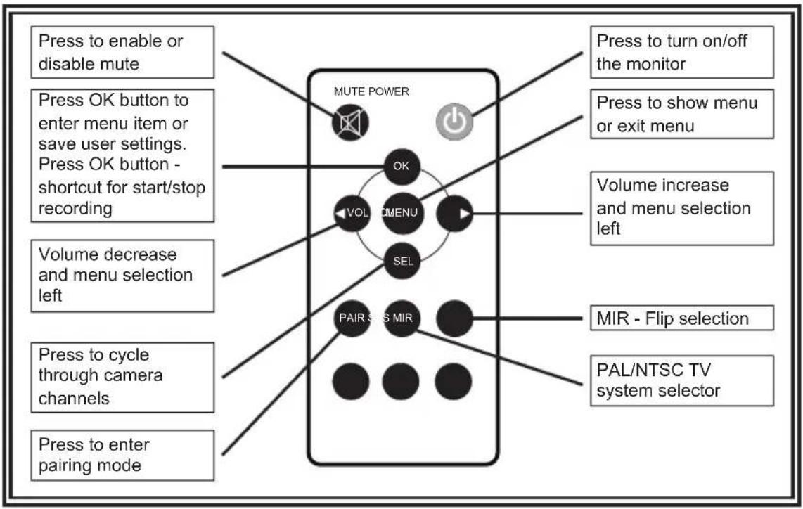
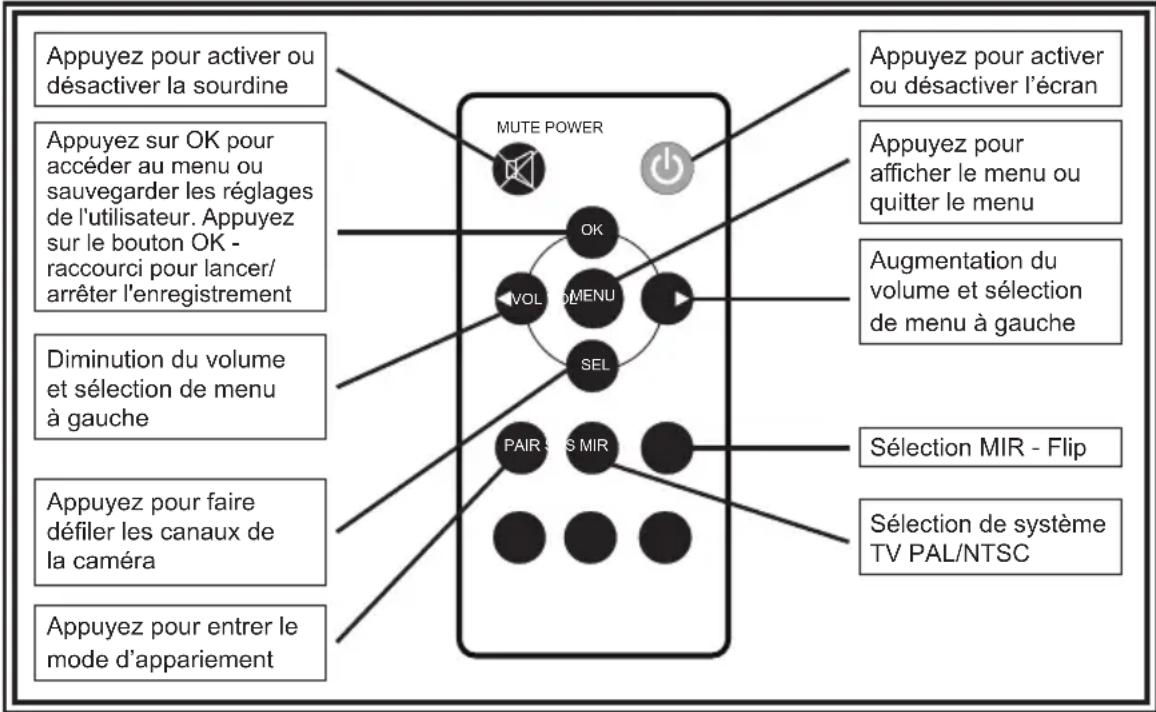
MONITOR PARTS IDENTIFICATION
flowchart
graph TD
    A["Press to enable or disable mute"] --> B["MUTE POWER"]
    C["Press OK button to enter menu item or save user settings. Press OK button - shortcut for start/stop recording"] --> B
    D["Volume decrease and menu selection left"] --> B
    E["Press to cycle through camera channels"] --> B
    F["Press to enter pairing mode"] --> B
    G["OK"] --> H["VMENU"]
    I["VOL"] --> H
    J["SEL"] --> H
    K["PAIR"] --> L["MIR"]
    M["PAL/NTSC TV system selector"] --> L
    N["Press to turn on/off the monitor"] --> B
    O["Press to show menu or exit menu"] --> B
    P["Volume increase and menu selection left"] --> B
    Q["MIR - Flip selection"] --> L
Pairing monitor to camera:
Cameras must be paired sequentially
Using the remote:
- Click menu on the remote
- Use the Right Arrow labeled Volume to go over to PAIRING menu option highlighted in yellow
- Confirm selection using the OK button
A. 50 second countdown will appear on monitor as pairing process is starting - Apply power to camera One during the 50 second countdown (using power and ground wires) must be 12 to 24 volts

=no/low signal

= full signal and you are ready to go to next step
- Image from Camera One will appear - this camera is now paired
A. DO NOT disconnect power from Camera One if adding multiple cameras
- If adding additional cameras, press SEL on the remote
A. This will take you to CAMERA Two
If pairing process is followed properly, monitor will stay paired with camera. Should camera power off or lose signal, reapply power to camera and monitor/camera will repair. This applies to all configurations. DO NOT PRESS PAIR BUTTON ON THE BACK OF THE CAMERA.
PAIRING 2nd CAMERA
- Click menu on the remote
- Use the Right Arrow labeled Volume to go over to PAIRING menu option highlighted in yellow
- Confirm selection using the OK button
A. 50 second countdown will appear on monitor as pairing process is starting - Apply power to camera Two during the 50 second countdown (using power and ground wires) must be 12 to 24 volts

= no/low signal

= full signal and you are ready to go to next step
- Image from Camera Two will appear - this camera is now paired
A. DO NOT disconnect power from Camera One or Camera TWO if adding multiple cameras
- If adding additional cameras, press SEL on the remote
A. This will take you to CAMERA Three
If pairing process is followed properly, monitor will stay paired with camera. Should camera power off or lose signal, reapply power to camera and monitor/camera will repair. This applies to all configurations. DO NOT PRESS PAIR BUTTON ON THE BACK OF THE CAMERA.
PAIRING 3rd CAMERA
- Click menu on the remote
- Use the Right Arrow labeled Volume to go over to PAIRING menu option highlighted in yellow
- Confirm selection using the OK button
A. 50 second countdown will appear on monitor as pairing process is starting - Apply power to camera Three during the 50 second countdown (using power and ground wires) must be 12 to 24 volts

= no/low signal

= full signal and you are ready to go to next step
- Image from Camera Three will appear - this camera is now paired
. DO NOT disconnect power from Camera One, Camera Two or Camera Three if adding multiple cameras
- If adding additional cameras, press SEL on the remote
A. This will take you to CAMERA Four
If pairing process is followed properly, monitor will stay paired with camera. Should camera power off or lose signal, reapply power to camera and monitor/camera will repair. This applies to all configurations. DO NOT PRESS PAIR BUTTON ON THE BACK OF THE CAMERA.
PAIRING 4th CAMERA
- Click menu on the remote
- Use the Right Arrow labeled Volume to go over to PAIRING menu option highlighted in yellow
- Confirm selection using the OK button
A. 50 second countdown will appear on monitor as pairing process is starting - Apply power to camera Four during the 50 second countdown (using power and ground wires) must be 12 to 24 volts

= no/low signal

= full signal and you are ready to go to next step
After all cameras have been paired, power them off and install onto the vehicle/apparatus.
If using a camera for a Reversing Camera:
Camera 3 is reversing camera
- One camera system - pair Camera 3
- Two camera system - pair Camera 1 and then skip 2 and pair with Camera 3
When in Single, Dual or Quad camera view, when the vehicle goes into reverse, Camera 3 (reversing camera) will take priority of the screen until vehicle is put back into drive.
Pairing the EC2030 - Remote Wireless Camera
Camera will go to sleep after 30 seconds without activity
- Click menu on the remote
- Use the Right Arrow labeled Volume to go over to PAIRING menu option highlighted in yellow
- Confirm selection using the OK button on remote
A. A 50 second countdown will appear as pairing is starting
- Turn on the wireless camera using the power button on the side
- Camera will pick up in 5-8 seconds
VOLUME ADJUSTMENT
During single image modes, the volume can be adjusted using the + and - buttons on the monitor or the < and > buttons on the remote.
During split/quad image modes, the audio from one camera is selected through the split audio menu option, see below for details. Return to any single image mode to adjust the volume.
SELECTING 2 CAM VIEW
Press the S button on the monitor until split view CAM1 and CAM2 appears on the screen. Press + or - on the monitor (or < or > on the remote control) to cycle through all the split camera views.
CUSTOM VIEW OVERRIDE SELECTION
To select the yellow trigger override, press the S button until split view CAM1 and CAM2 is on the screen. Apply and hold power to yellow trigger wire and press the + or - button on the monitor (< or > on the remote) to cycle through all split camera views, including quad view. When desired split or quad override view is found, remove yellow trigger wire from power. Wait for camera view to reset. Press S to change to camera view and return to normal viewing mode. Touch the yellow trigger wire to power wire to test if the trigger override is working properly. This view will override all standard views except reversing trigger wire when power is applied to yellow.
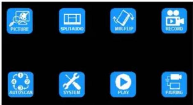
MENU OPTIONS
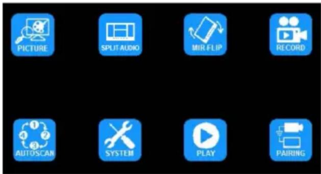
Press M (or MENU on the remote) to display the following options and settings:
-
PICTURE 5. AUTOSCAN
-
SPLIT-AUDIO 6. SYSTEM
-
MIR-FLIP 7. PLAY
-
RECORD 8. PAIRING

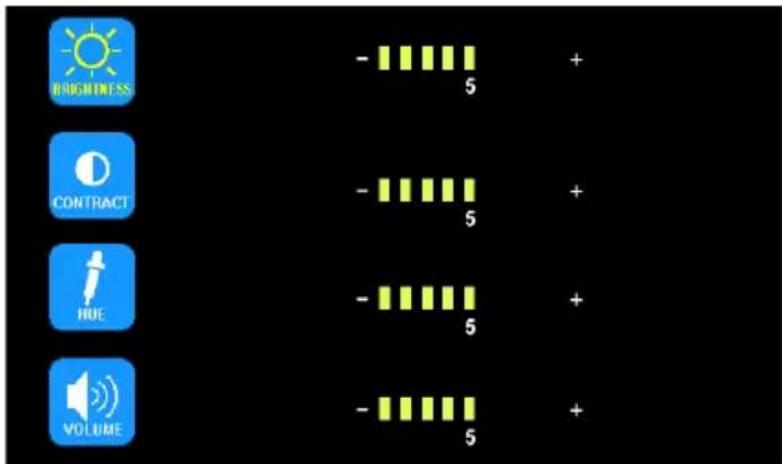
MENU OPTION: PICTURE IMAGE MODE OPTIONS
Using the monitor:
-
Press S to enter the single image mode to be adjusted.
-
Press M to enter the Menu
-
Use the + or - to highlight the PICTURE Option
-
Press the down arrow to enter the PICTURE Option
-
Use the + or - to highlight the desired adjustment
-
Press the down arrow to enter the adjustment option
-
Use the + or - to change the settings
-
Press the down arrow to exit the adjustment option
-
Press M twice to return to the main screen
Using the remote:
-
Press SEL to enter the single image mode to be adjusted
-
Press MENU to enter the Menu
-
Use the < or > to highlight the PICTURE Option
-
Press OK to enter the PICTURE Option
-
Use the < or > to highlight the desired adjustment
-
Press OK to enter the adjustment option
-
Use the < or > to change the settings
-
Press OK to exit the adjustment option
-
Press MENU twice to return to the main screen

MENU OPTION: SPLIT-AUDIO ON/OFF SELECTION
Audio from one camera is selected through the split audio menu option. Return to any single image mode to adjust the volume. The volume selected during any single camera image mode will carry over to all other image modes. Volume can not be adjusted during split or quad image modes.
Using the monitor:
Using the remote:
- Press M to enter the Menu
- Use the + or - to highlight the SPLIT-AUDIO option
- Press the down arrow to enter the SPLIT-AUDIO menu
- Use the + or - to highlight/select the camera to deliver audio
-
Press M twice to return to the main screen
-
Press MENU to enter the Menu
- Use the < or > to highlight the SPLIT-AUDIO option
- Press OK to enter the SPLIT-AUDIO menu
- Use the < or > to highlight/select the camera to deliver audio
- Press MENU twice to return to the main screen


MENU OPTION: MIR-FLIP ROTATION/FLIP OPTIONS
Using the monitor:
- Press S to enter the single image mode to be adjusted.
- Press M to enter the Menu
- Use the + or - to highlight the MIR-FLIP Option
- Press the down arrow to enter the MIR-FLIP Option
- Use the + or - to highlight the desired orientation
- Press M twice to return to the main screen
Using the remote:
- Press SEL to enter the single image mode to be adjusted
- Press MIR to rotate the image


MENU OPTION: RECORD RECORDING OPTIONS
The record function is passcode protected. At initial startup, a 4 digit numerical passcode can be established in order to access the menu. Press the down arrow to select first digit, when number is red, use + or - to select 0 through 9. Press the down arrow to move to the next number and continued until desired 4 digit pin is finished. Press the down arrow to confirm. This passcode will also be used for accessing the playback menu and will be the same 4 digits. In order to access the menu again, you will be prompted to enter the passcode again.
Once the pass code has been set, you can set automatic recording upon start up by selecting the record menu by pressing the down arrow. Use the + or - to select ON or OFF. Press the down arrow to exit and press M to exit the menu.
Enable/Disable Recording
A blue rectangle at the top of the monitor will indicate active recording as long as a mini SD card has been been installed and formatted. See further sections for details. To enable or disable recording in split or quad view, press the down arrow on the monitor or the OK on the remote.
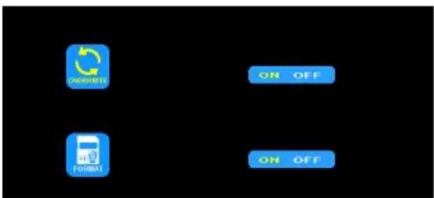
Once OVERWRITE is enabled, any recording that takes place after the mini SD card is to capacity, the system will automatically start overwriting existing recordings. See the table below for recording capacities.
To enable overwrite or to format a mini SG card
Using the monitor:
- Press M to enter the Menu
- Use the + or - to highlight the RECORD Option
- Press the down arrow to enter the RECORD Option
- Use the + or - to highlight the desired adjustment
- Press M twice to return to the main screen
Using the remote:
- Press MENU to enter the Menu
- Use the < or > to highlight the RECORD Option
- Press OK to enter the RECORD Option
- Use the < or > to highlight the desired adjustment
- Press MENU twice to return to the main screen
| Mode 8G 16G 32G 64G 126G | |||
| SINGLE (640x480x1) 14h 28h 55h 110h 220h | |||
| QUAD (320x240x4) 11h 22h 43h 86h 172h | |||
| SPLIT (400x480x2) 13h 25h 50h 101h 201h |
AUTOSCAN is disabled by default when all cameras are set to off in the AUTOSCAN menu. AUTOSCAN is enabled once one or more cameras are set to ON in the AUTOSCAN menu. Once enabled, AUTOSCAN occurs as an additional image mode between the split and CAM1 image modes. The SCANTIME, or time interval for each camera, is in seconds.
Using the monitor:
- Press M to enter the Menu
- Use the + or - to highlight the AUTOSCAN Option
- Press the down arrow to enter the AUTOSCAN Option
- Use the + or - to highlight the desired adjustment
- Press the down arrow to enter the adjustment option
- Use the + or - to change the settings
- Press the down arrow to exit the adjustment option
- Press M twice to return to the main screen
Using the remote:
- Press MENU to enter the Menu
- Use the < or > to highlight the AUTOSCAN Option
- Press OK to enter the AUTOSCAN Option
- Use the < or > to highlight the desired adjustment
- Press OK to enter the adjustment option
- Use the < or > to change the settings
- Press OK to exit the adjustment option
- Press MENU twice to return to the main screen
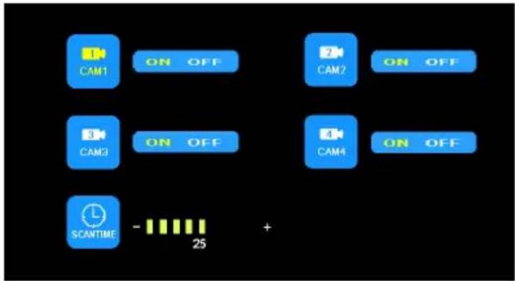
flowchart
graph TD
    A["1 CAM1"] --> B["ON OFF"]
    C["2 CAM2"] --> D["ON OFF"]
    E["3 CAM3"] --> F["ON OFF"]
    G["4 CAM4"] --> H["ON OFF"]
    I["SCANTIME"] --> J["- 25"]
    J --> K["+"]

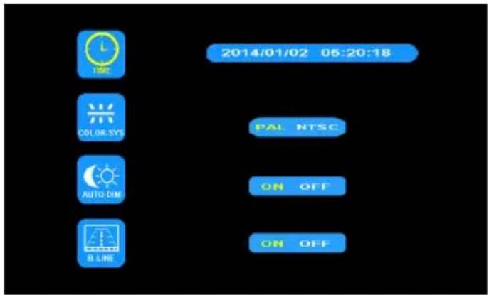
MENU OPTION: SYSTEM SYSTEM OPTIONS
When AUTO-DIM is set to ON, the backlight automatically adjusts in accordance with the outer brightness. When the B-LINE is set to ON, the electronic distance label will be displayed when the blue camera 3 trigger wire is activated.
Both PAL and NTSC color system options are available. PAL offers automated color correction and 25 frames per second (fps), popular in Europe and Australia, while NTSC uses manual color correction and 30 fps, popular in the U.S. and Asia.
If using an SD Card, you will need to reset the date/time stamp in the system options before SD Card has been installed.
Using the monitor:
- Press M to enter the Menu
- Use the + or - to highlight the SYSTEM Option
- Press the down arrow to enter the SYSTEM Option
- Use the + or - to highlight the desired adjustment
- Press the down arrow to enter the adjustment option
- Use the + or - to change the settings
- Press the down arrow to exit the adjustment option
- Press M twice to return to the main screen
Using the remote:
- Press MENU to enter the Menu
- Use the < or > to highlight the SYSTEM Option
- Press OK to enter the SYSTEM Option
- Use the < or > to highlight the desired adjustment
- Press OK to enter the adjustment option
- Use the < or > to change the settings
- Press OK to exit the adjustment option
- Press MENU twice to return to the main screen
See Record section for setting up a passcode. In order to access the menu after initial setup, you will need the passcode.
Using the monitor:
- Press S to enter the single image mode to be adjusted.
- Press M to enter the Menu
- Use the + or - to highlight the PLAY Option
- Press the down arrow to enter the PLAY Option
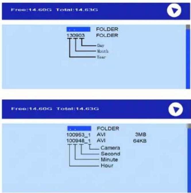
- Use the + or - to highlight the desired folder labeled by the dates. (See below)
- Press the down arrow to enter the folder.
- Use the + or - to highlight the desired recording labeled by the time and image channel. (See below)
- Press the down arrow to play the recording
- Press M twice to return to the main screen
Using the remote:
- Press SEL to enter the single image mode to be adjusted
- Press MENU to enter the Menu
- Use the < or > to highlight the PLAY Option
- Press OK to enter PLAY Option.
- Use the < or > to highlight the desired recording labeled by the time and image channel. (See below)
- Press OK to enter the folder
- Use the < or > to highlight the desired recording labeled by the time and image channel. (See below)
- Press OK to play the recording
- Press MENU twice to return to the main screen
Verify Media Player has most up to date software if given a system error on playback.
MONITOR MODEL EC7008-WM INSTALLATION AND MOUNTING:

WARNING!
To prevent accidental shock, DO NOT OPEN THE MONITOR CASE. Opening the monitor case will expose the inside of the monitor to conditions that could adversely affect performance. Any evidence of tampering with sealed components will void the warranty.
Important! Do not expose the monitor to water, it is not waterproof. Any water that leaks into the monitor could cause extensive damage.
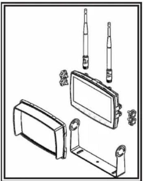
Carefully remove the unit from its packaging. Examine the unit for transit damage. If damage is found, return the product to your local dealer for warranty replacement. Do not use damaged or broken parts.
U-Bracket Monitor Mounting Instructions
- Select a level surface for installation.
- Drill mounting holes using the lower U-bracket as a template and attach the U-bracket with user supplied hardware.
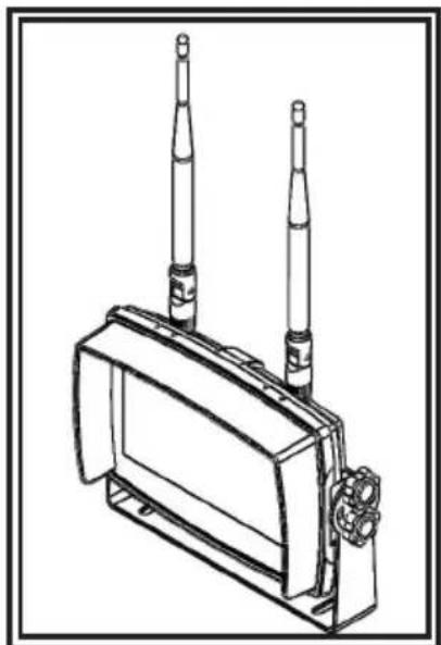
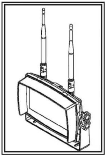
- Install the monitor on the U-bracket as shown in Figure 2. Adjust the monitor's position for the best viewing angle before tightening the two screws on each end.
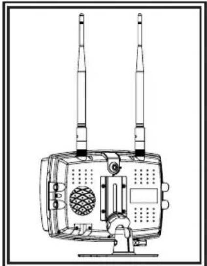
- Attach the sun-visor as shown. Attach the antennas so they point upward as shown in Figure 3.
natural_image
Technical line drawing of electronic components including a battery pack, motor, and connectors (no text or symbols)Figure 2

natural_image
Line drawing of a portable electronic device with two vertical tubes and a front panel (no text or symbols)Figure 3
Pedestal Mounting Instructions:
- Select a level surface for installation.
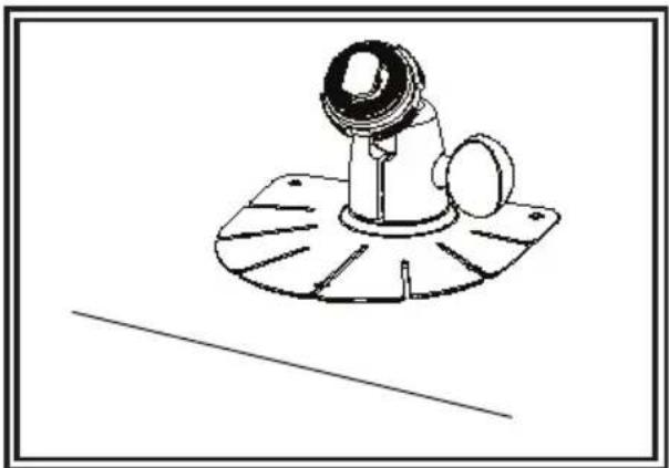
- For mounting the pedestal using the adhesive, prep the surface using rubbing alcohol before installation as shown in Figure 4.
- For mounting the pedestal using screws, drill mounting holes using the pedestal as a template and attach with user supplied hardware.
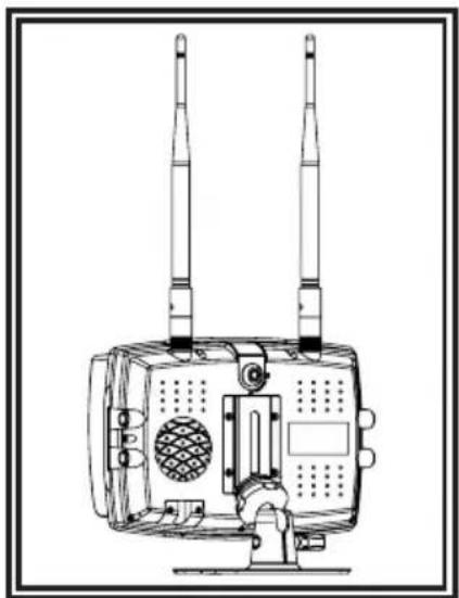
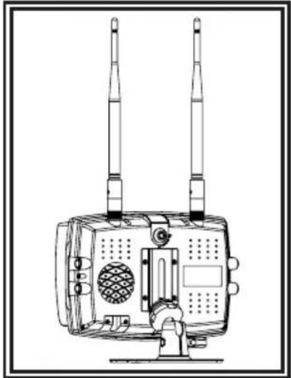
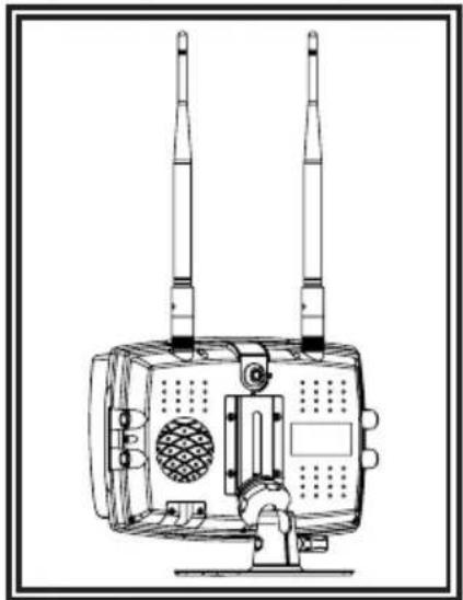
- Install the monitor and sun-visor on the pedestal mount as shown in Figure 5. Adjust the monitor's position for best viewing angel before tightening the set screw on the pedestal mount. Attach the antennas so they point upward.
natural_image
Technical line drawing of a mechanical component with a base plate and cylindrical head (no text or symbols)Figure 4
natural_image
Technical line drawing of a mounted electronic device with two vertical antennas and a mesh chamber (no text or symbols)Figure 5
Notes:
- Larger wires and tight connections will provide longer service life for components. For high current wires it is recommended that terminal blocks or soldered connections be used with shrink tubing to protect the connections. Do not use insulation displacement connectors (e.g., 3M Scotchlock type connectors)
- Route wiring using grommets and sealant when passing through compartment walls. Minimize the number of splices to reduce voltage drop. High ambient temperatures (e.g., under-hood) will significantly reduce the current carrying capacity of wires, fuses, and circuit breakers. All wiring should conform to the minimum wire size and other recommendations of the manufacturer and be protected from moving parts and hot surfaces. Looms, grommets, cable ties, and similar installation hardware should be used to anchor and protect all wiring.
- Fuses or circuit breakers should be located as close to the power takeoff points as possible and properly sized to protect the wiring and devices.
- Particular attention should be paid to the location and method of making electrical connections and splices to protect these points from corrosion and loss of conductivity.
- Ground termination should be only be made to substantial chassis components, preferably directly to the vehicle battery.
- Circuit breakers are very sensitive to high temperatures and will "false trip" when mounted in hot environments or operated close to their capacity.
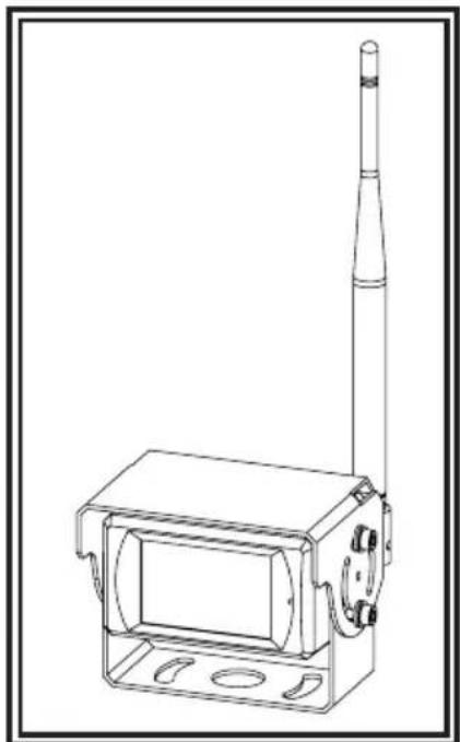
CAMERA MODEL EC2027-WC INSTALLATION AND MOUNTING:
Important! Mount the camera at a location that provides the best view of the area immediately behind the vehicle. Generally, mounting locations toward the top of the vehicle provide the best field of view. Lower mounting locations reduce the field of view and increase the likelihood of damage from road spray.
Carefully remove the unit from its packaging. Examine the unit for transit damage. If damage is found, return the product to your local dealer for warranty replacement. Do not use damaged or broken parts.
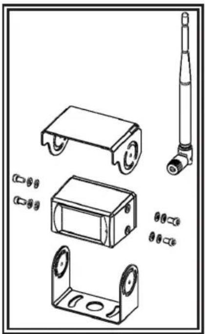
U-BRACKET CAMERA MOUNTING INSTRUCTIONS:
- Select a level surface for installation.
- Drill mounting holes using the lower U-bracket as a template and attach the U-bracket with user supplied hardware.
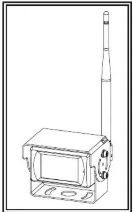
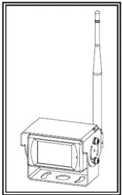
- Install the camera and sun-visor on the U-bracket as shown in Figure 6.
- Adjust the camera's position for the best viewing angle before tightening the two screws on each end.
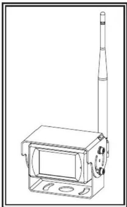
- Attach the antenna so that it is vertical as shown in Figure 7.
natural_image
Technical line drawing of mechanical components including wheels, housing, and a cylindrical component (no text or symbols)Figure 6
natural_image
Technical line drawing of a mechanical device with a vertical rod and rectangular housing (no text or symbols)Figure 7
For reference only
WIRING INSTRUCTIONS:
Important! Waterproof all connections whether inside or outside the vehicle by using sealant and wrapping with insulation tape. Wrap tape tightly, overlapping by one-half widths so there are no gaps.
The unit is designed for electrical systems from 12 to 24 VDC (10 to 30 VDC extremes). The wiring for all systems is:
Red Wire Positive (+) Black Wire Negative (-)
All wiring should be a minimum of 20 AWG. A 3-amp fuse in the positive line is required (see Figure 8).
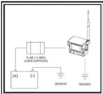
Figure 8
Replacement Parts and Accessories
| Description Part Number |
| CAMERA EC2027-WC |
| MONITOR EC7008-WM |
| CABLE PCY-7008-WM |
| ANTENNA ECANTE-R |
| PEDESTAL MOUNT MB01 |
| SUN-VISOR AS7000SS |
Specifications:
| Camera | EC2027-WC |
| Image Device | 1/3" CMOS |
| TV System | PAL/NTSC |
| Array Size | 728x488 Pixels |
| Sensing Area 4.6228mm x 3.6112mm | |
| Scanning System | 2:1 Interlace |
| Sync. System | Internal |
| Resolution | 500 TV Lines |
| Min. Illumination | 0.1 Lux (day), 0 Lux (with IR) |
| Microphone | Yes |
| Video Output | 1.0 vp-p, 75 Ohm |
| AGC | Auto |
| S/N Ratio | Better than 48 dB |
| White Balance | Auto |
| BLC Auto | |
| Current Consumption | Max. 250mA@12V/140mA@24V |
| Operating Frequency | 2400-2483.5-MHz |
| Transmitting Distance | 120M (barrier free) |
| Decompression Form | MPEG4 |
| Transmit Output Power | 17 dBm |
| RF Bit Rate | 4Mbps |
| Operating Temperature | -20°C~70°C, RH 90% Max. |
| Storage Temperature | -30°C~80°C, RH 90% Max. |
| Monitor EC7008-WK 7" LCD Monitor | |
| LCD Size 7" | |
| Resolution 800 x 3 (RGB) x 480 | |
| Contrast 500:1 | |
| Brightness 400 cd/m2 | |
| Viewing Angle U: 50 / D: 70, R/L: 70 | |
| DOT Pitch 0.0642(W) x 0.1790(H) | |
| Aspect Ratio 16:9 | |
| Operating Frequency 2400 - 2483.5 MHz | |
| Receiving Sensitivity -89 dBm | |
| Decompression Form MPEG4 | |
| Modulation | 2.4G FSK/GFSK/ Line of sight -unobstructed |
| Time Delay | 120ms |
| Transmitting Distance | 120 M |
| Micro-SD/TF Card Max. | 128G |
| System Format | PAL/NTSC |
| Power Supply | DC 10-32V |
| Power Consumption Max. | 6W |
| Loudspeaker | 1.5W/8 |
| Operating Temperature | -20°~+70°C, RH90% |
| Storage Temperature | -30°~+80°C, RH90% |
Electronics Controls Company "ECCO" (Manufacturer)
ECCO warrants that on the date of purchase, this product will conform to ECCO's specifications for this product (which are available from ECCO upon request). This Limited Warranty extends for twelve (12) months from the date of purchase.
DAMAGE TO PARTS OR PRODUCTS RESULTING FROM TAMPERING, ACCIDENT, ABUSE, MISUSE, NEGLIGENCE, UNAPPROVED MODIFICATIONS, FIRE OR OTHER HAZARD; IMPROPER INSTALLATION OR OPERATION; OR NOT BEING MAINTAINED IN ACCORDANCE WITH THE MAINTENANCE PROCEDURES SET FORTH IN ECCO'S INSTALLATION AND OPERATING INSTRUCTIONS VOIDS THIS LIMITED WARRANTY.
Exclusion of Other Warranties:
ECCO MAKES NO OTHER WARRANTIES, EXPRESSED OR IMPLIED. THE IMPLIED WARRANTIES FOR MERCHANTABILITY, QUALITY OR FITNESS FOR A PARTICULAR PURPOSE, OR ARISING FROM A COURSE OF DEALING, USAGE OR TRADE PRACTICE ARE HEREBY EXCLUDED AND SHALL NOT APPLY TO THE PRODUCT AND ARE HEREBY DISCLAIMED, EXCEPT TO THE EXTENT PROHIBITED BY APPLICABLE LAW. ORAL STATEMENTS OR REPRESENTATIONS ABOUT THE PRODUCT DO NOT CONSTITUTE WARRANTIES.
Remedies and Limitation of Liability:
ECCO'S SOLE LIABILITY AND BUYER'S EXCLUSIVE REMEDY IN CONTRACT, TORT (INCLUDING NEGLIGENCE), OR UNDER ANY OTHER THEORY AGAINST ECCO REGARDING THE PRODUCT AND ITS USE SHALL BE, AT ECCO'S DISCRETION, THE REPLACEMENT OR REPAIR OF THE PRODUCT, OR THE REFUND OF THE PURCHASE PRICE PAID BY BUYER FOR NON-CONFORMING PRODUCT. IN NO EVENT SHALL ECCO'S LIABILITY ARISING OUT OF THIS LIMITED WARRANTY OR ANY OTHER CLAIM RELATED TO THE ECCO'S PRODUCTS EXCEED THE AMOUNT PAID FOR THE PRODUCT BY BUYER AT THE TIME OF THE ORIGINAL PURCHASE. IN NO EVENT SHALL ECCO BE LIABLE FOR LOST PROFITS, THE COST OF SUBSTITUTE EQUIPMENT OR LABOR, PROPERTY DAMAGE, OR OTHER SPECIAL, CONSEQUENTIAL, OR INCIDENTAL DAMAGES BASED UPON ANY CLAIM FOR BREACH OF CONTRACT, IMPROPER INSTALLATION, NEGLIGENCE, OR OTHER CLAIM, EVEN IF ECCO OR A REPRESENTATIVE OF ECCO HAS BEEN ADVISED OF THE POSSIBILITY OF SUCH DAMAGES. ECCO SHALL HAVE NO FURTHER OBLIGATION OR LIABILITY WITH RESPECT TO THE PRODUCT OR ITS SALE, OPERATION AND USE, AND ECCO NEITHER ASSUMES NOR AUTHORIZES THE ASSUMPTION OF ANY OTHER OBLIGATION OR LIABILITY IN CONNECTION WITH SUCH PRODUCT.
This Limited Warranty defines specific legal rights. You may have other legal rights which vary from jurisdiction to jurisdiction. Some jurisdictions do not allow the exclusion or limitation of incidental or consequential damages.
Declaration of conformity:
This device complies with Part 15 of the FCC Rules. Operation is subject to the following two conditions:
(1) This device may not cause harmful interference.
(2) This device must accept any interference received, including interference that may cause undesired operation.


ECCO®
833 West Diamond St
Boise, Idaho 83705
Customer Service
USA 800-635-5900
UK +44 (0)113 237 5340
AUS +61 (0)3 63322444
www.eccoesg.com
An ECCO SAFETY GROUP™ Brand
www.eccosafetygroup.com

¡ADVERTENCIA!
Verify Media Player has most up to date software if given a system error on playback.
natural_image
Technical line drawing of electronic components including a battery pack, display case, and two cylindrical batteries (no text or symbols)Figura 2
natural_image
Line drawing of a device with two vertical tubes mounted on a base (no text or symbols)Figura 3
natural_image
Technical line drawing of a mechanical component with a base and mounting base (no text or symbols)Figura 4
natural_image
Technical line drawing of a mounted military radar or communication device with two tall antennas and control panels (no text or symbols)Figura 5
Notas:
natural_image
Technical line drawing of mechanical components including wheels, housing, and a cylindrical component (no text or symbols)Figura 6
natural_image
Technical line drawing of a mechanical device with a vertical rod and rectangular housing (no text or symbols)*Trigger wire may or may not be required based on your specific application.
INSTRUCTIONS D'INSTALLATION:
Verify Media Player has most up to date software if given a system error on playback.
MODÈLE D'ÉCRAN EC7008-WM INSTALLATION ET MONTAGE :

AVERTISSEMENT!
natural_image
Technical line drawing of electronic components including a battery pack, two test tubes, and a display case (no text or symbols)Figure 2
natural_image
Line drawing of a device with two vertical tubes mounted on a base (no text or symbols)Figure 3
natural_image
Technical line drawing of a mechanical component with a base plate and cylindrical head (no text or symbols)Figure 4
natural_image
Technical line drawing of a dual-mounted antenna or radar device with two vertical antennas and a central display unit (no text or symbols)Figure 5
Remarques :
natural_image
Technical line drawing of mechanical components including wheels, housing, and a cylindrical component (no text or symbols)Figure 6
natural_image
Technical line drawing of a mechanical device with a vertical rod and rectangular housing (no text or symbols)Press M (or MENU on the remote) to display the following options and settings:
- PICTURE (BILD) 5. AUTOSCAN (AUTOMATISCHER SCAN)
- SPLIT-AUDIO (GETEILTES AUDIO) 6. SYSTEM
- MIR-FLIP (MIR UMDREHEN) 7. PLAY (WIEDERGABE)
- RECORD (AUFNAHME) 8. PAIRING (KOPPLUNG)

MENU OPTION: PICTURE IMAGE MODE OPTIONS
Using the monitor:
MENÜPTION: MIR-FLIP (MIR UMDREHEN) OPTIONEN ZUM DREHEN/UMKEHREN
Über den Monitor:
MENÜPTION: SYSTEM SYSTEMOPTIONEN
natural_image
Technical line drawing of electronic components including a battery pack, motor, and two cylindrical batteries (no text or symbols)Abbildung 2

natural_image
Line drawing of a portable electronic device with two vertical tubes and a front panel (no text or symbols)Abbildung 3
natural_image
Technical line drawing of a mechanical device with a cylindrical component mounted on a base plate (no text or symbols)Abbildung 4
natural_image
Technical line drawing of a dual-mounted antenna device with two vertical antennas and a central display (no text or symbols)Abbildung 5
Hinweise:
natural_image
Technical line drawing of mechanical components including wheels, housing, and a cylindrical component (no text or symbols)Abbildung 6