RMX95 - DJ Equipment Reloop - Free user manual and instructions
Find the device manual for free RMX95 Reloop in PDF.
| Product type | Professional 4-channel DJ mixer |
| Dimensions (W x H x D) | 322 x 107.5 x 387 mm |
| Weight | 6.85 kg |
| Power supply | Mains 230 V, 50 Hz, consumption 29 W |
| Audio inputs | 7 x Line (RCA), 2 x Phono (RCA), 1 x AUX, 2 x Mic (6.35 mm jack) |
| Audio outputs | Master XLR (balanced), Master RCA (unbalanced), Booth TRS (balanced), Record RCA (unbalanced), 2 x Headphone (6.35 mm and 3.5 mm jack) |
| Equalizer | 3-band per channel (Kill/Classic), 2-band Mic, adjustable EQ curve |
| Filter | Bipolar filter (Low/High pass) per channel + global resonance |
| DSP effects | 13 effects: Echo, Reverb, Flanger, Phaser, Vinyl Brake, Loop Roll, Noise, Pitch Shift, Delay, Ping Pong, Tape Delay, Bit Crusher, Transformer |
| Crossfader | Adjustable curve, assignable per channel (A/B/Thru), Innofader compatible |
| Line faders | Adjustable curve via Linefader Curve control |
| USB interface | 2 USB-B ports for computer, USB-A hub for peripherals |
| BPM counter | Automatic and manual (Tap), for channels and effects |
| Frequency response | 20 Hz - 20 kHz (+2/-3 dB) |
| Maintenance | Clean with a slightly damp cloth without solvents; no internal parts to maintain |
| Safety | Do not expose to moisture; disconnect before cleaning; use on a stable surface |
| Spare parts and repairability | Crossfader and faders replaceable; maintenance by qualified personnel |
| General information | Warranty: not covered in case of modification; comply with CE guidelines |
Frequently Asked Questions - RMX95 Reloop
User questions about RMX95 Reloop
0 question about this device. Answer the ones you know or ask your own.
Ask a new question about this device
Download the instructions for your DJ Equipment in PDF format for free! Find your manual RMX95 - Reloop and take your electronic device back in hand. On this page are published all the documents necessary for the use of your device. RMX95 by Reloop.
USER MANUAL RMX95 Reloop
natural_image
Black industrial mixing console with multiple knobs and dials, no visible text or symbols on the device itself.Bedienungsanleitung
ACHTUNG!
For your own safety, please read this operation manual carefully before initial operation! All persons involved in the installation, setting-up, operation, maintenance and service of this device must be appropriately qualified and observe this operation manual in detail. This product complies with the requirements of the applicable European and national regulations. Conformity has been proven. The respective statements and documents are deposited at the manufacturer.
Mode d'emploi
ATTENTION!
To prevent fire or avoid an electric shock do not expose the device to water or fluids! Never open the housing!
ATTENTION!
Keep information for further reference!
5.2.9 MIC BTH (MIC BOOTH)
5.2.11 BTH SRC (BOOTH SOURCE)

Note: Please close all applications and disconnect all other devices.
Click Start to continue

EQ Range Isolator bei 70 Hz, 1 kHz, 13 kHz: -90 dB (total kill)/+9 dB
Subject to alterations.
Illustrations similar to original product.
Misprints excepted.
CAUTION!
For your own safety, please read this operation manual carefully before initial operation! All persons involved in the installation, setting-up, operation, maintenance and service of this device must be appropriately qualified and observe this operation manual in detail. This product complies with the requirements of the applicable European and national regulations. Conformity has been proven. The respective statements and documents are deposited at the manufacturer.
Please remove the RMX-95 from its packaging. Check before initial operation to make sure that the device has not been visibly damaged during transport. If you detect any damage to the power cable or the casing, do not operate the device. Contact your specialised dealer.
SAFETY INSTRUCTIONS
CAUTION!
Please exercise particular caution when handling AC 100 - 240 V, 50/60Hz power voltage. This voltage rating may lead to a critical electrical shock! Any damage caused by the non-observance of this operation manual excludes any warranty claims. The manufacturer is not liable for any damage to property or for personal injury caused by Improper handling or non-observance of the safety instructions.
WARNING! To prevent fire or avoid an electric shock do not expose the device to water or fluids! Never open the housing!
- This device left the factory in perfect condition. To maintain this condition and to ensure a risk-free operation the user must observe the safety instructions and warnings contained in this operation manual.
- For reasons of safety and certification (CE) the unauthorised conversion and/or modification of the device is prohibited. Please note that in the event of damage caused by the manual modification to this device any warranty claims are excluded.
- The inside of the device does not contain any parts which require maintenance, with the exception of wear parts that can be exchanged from the outside. Qualified staff must carry out maintenance, otherwise the warranty does not apply!
- The fuse must exclusively be exchanged against fuses of the same class, with the same trigger features and nominal current rating.
- Ensure that the power will only be supplied after the device has been fully set up.
- Only use cables that comply with regulations. Observe that all jacks and bushes are tightened and correctly hooked up. Refer to your dealer, if you have any questions.
- Ensure that when setting up the product, the mains cable is not squashed or damaged by sharp edges.
- Prevent the mains cable from coming into contact with other cables! Exercise great care when handling mains cables and connections. Never touch these parts with wet hands!
- Connect the power cable exclusively to appropriate shock-proof outlets. The only supply point to be used is a supply outlet in accordance with specifications of the public supply network.
- Disconnect the device from the supply outlet when not in use and before cleaning! Be sure to hold the mains plug by the body. Never pull the mains cord!
- Position the device on a horizontal and stable low-flame base.
- Avoid any concussions or violent impact when installing or operating the device.
- When selecting the location of installation, make sure that the device is not exposed to excessive heat, humidity and dust. Be sure that no cables lie around openly. You will endanger your own safety and that of others!
- Do not rest any containers filled with liquid that could easily spill onto the device or in its immediate vicinity. If, however, fluids should access the inside of the device, immediately disconnect the mains plug. Have the device checked by a qualified service technician before re-use. Damage caused by fluids inside the device is excluded from warranty.
- Do not operate the device under extremely hot (in excess of 35^ ) or extremely cold (below 5^ ) conditions. Keep the device away from direct exposure to the sun and heat sources such as radiators, ovens, etc. (even during transport in a closed vehicle). Always ensure sufficient ventilation.
- The device must not be operated after being taken from a cold environment into a warm environment. The condensation caused hereby may destroy your device. Do not switch on or operate the device until it has reached ambient temperature!
- Controls and switches should never be treated with spray-on cleaning agents and lubricants. This device should only be cleaned with a damp cloth. Never use solvents or cleaning fluids with a petroleum base for cleaning.
- When relocating, the device should be transported in its original packaging.
- When starting operation, the crossfaders and volume controls of your amplifier must be set to minimum level. Bring the loudspeaker switches into the "OFF" position. Wait between 8 to 10 seconds before increasing the volume to avoid damage to loudspeakers.
• Devices supplied by voltage should not be left in the hands of children. Please exercise particular care when in the presence of children. - At commercial facilities the regulations for the prevention of accidents as stipulated by the organization of professional associations must be observed.
- At schools, training facilities, hobby and self-help workshops the operation of the device must be monitored with responsibility by trained staff.
- Keep this operation manual in a safe place for later reference in the event of questions or problems.
APPLICATION IN ACCORDANCE WITH REGULATIONS
- This device is a 4-channel DJ controller, which can regulate and mix audio signals. The device needs to be connected to a tablet or computer and an audio amplifier or active speakers.
- If the device is used for any other purposes than those described in the operation manual, damage can be caused to the product, leading to the exclusion of warranty rights. Moreover, any other application that does not comply with the specified purpose harbours risks such as short circuit, fire, electric shock, etc.
- The serial number determined by the manufacturer must never be removed to uphold the warranty rights.
MAINTENANCE
- Check the technical safety of the device regularly for damage to the mains line or the casing, as well as for wear of wear parts such as rotary and sliding switches.
- If it is to be assumed that the safe operation is no longer feasible, then the device must be disconnected and secured against accidental use. Always disconnect the mains plug from the outlet!
- It must be assumed that a safe operation is no longer feasible, if the device bears visible defects, if the device no longer functions, following longer storage under unfavourable conditions or after major transport stress.
text_image
WARNING FOR PROJECT ELECTRIC SWITCH DO NOT PUSHING ITEMS TO CREATE CHECKS OF FIRST DURING TIME START TO SURELLING ORDER CONTINUING WARNING FOR SELECT THE RESET FOR AND ELECTRIC SHORT TO NOT ENTER FROM ANY CHANGE TO RISKING ITEMS ON ITEMS SHOULD NOT REBEeding FOR USE OR OVERHOLD LIMITED. OFF 59 ON POWER AC IN - MST 2 REC LINE CD CH4 PHOHD CD CH3 PHOHO CD CH2 LINE CD CH1 USD INTERFACE SMART LINK ACTIVE USB BUS MST 1 (BALANCED) BOOTN (TRS) USB B USB A 56 55 57 L 50 R L (MOXIMO) 58 R 51 CE UK EAC
-
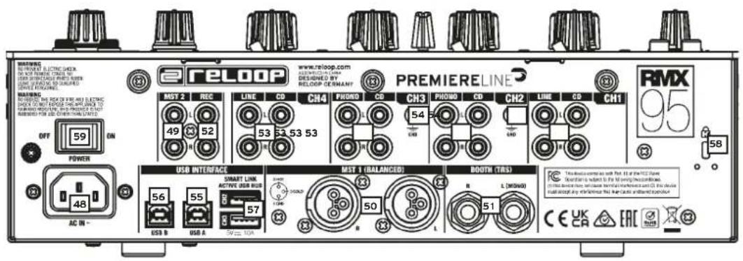
Signal input selector switch
-
Gain
-
3-band EQ
-
LEDs
-
Filter
-
Cue button
-
Line fader
-
Crossfader assignment switch
-
Crossfader
-
Crossfader curve
-
Tap button, for manually tapping the BPM
-
Linefader curve
-
Auto/Tap button, for automatic BPM detection
-
EQ curve switch
1.2.2 MIC CHANNEL
-
DJ Mic 1/AUX level
-
Level LED for DJ Mic/AUX
-
Mic 2 level
-
Level LED for DJ Mic 2
-
2-band EQ for DJ Mic 1
20a. Talkover switch
20b. Mic ON button
1.2.3 HEADPHONES SECTION
-
Split switch (Mono/Stereo split switch)
-
Cue EQ (EQ for headphone output)
-
Cue mix (ratio between cue and master signal)
-
Cue VOL (volume control for headphone output)
1.2.4 MASTER SECTION
-
Master Level, controls the master volume
-
LED for the master signal
-
Mono/stereo switch for booth output
-
Booth level control, adjusts the monitor volume
-
Filter resonance, adjusts the resonance settings for the sound filters
1.2.5 FX SECTION
-
FX Select
-
FX Routing
-
Time encoder
-
Time-beat buttons
-
FX-Frequency control
-
Level/Depth control
-
FX On
-
Display
1.2.6 DISPLAY
-
FX / PARAM
-
FX channel display
-
Time / Length
-
BPM Channel / FX
-
BPM CUE display
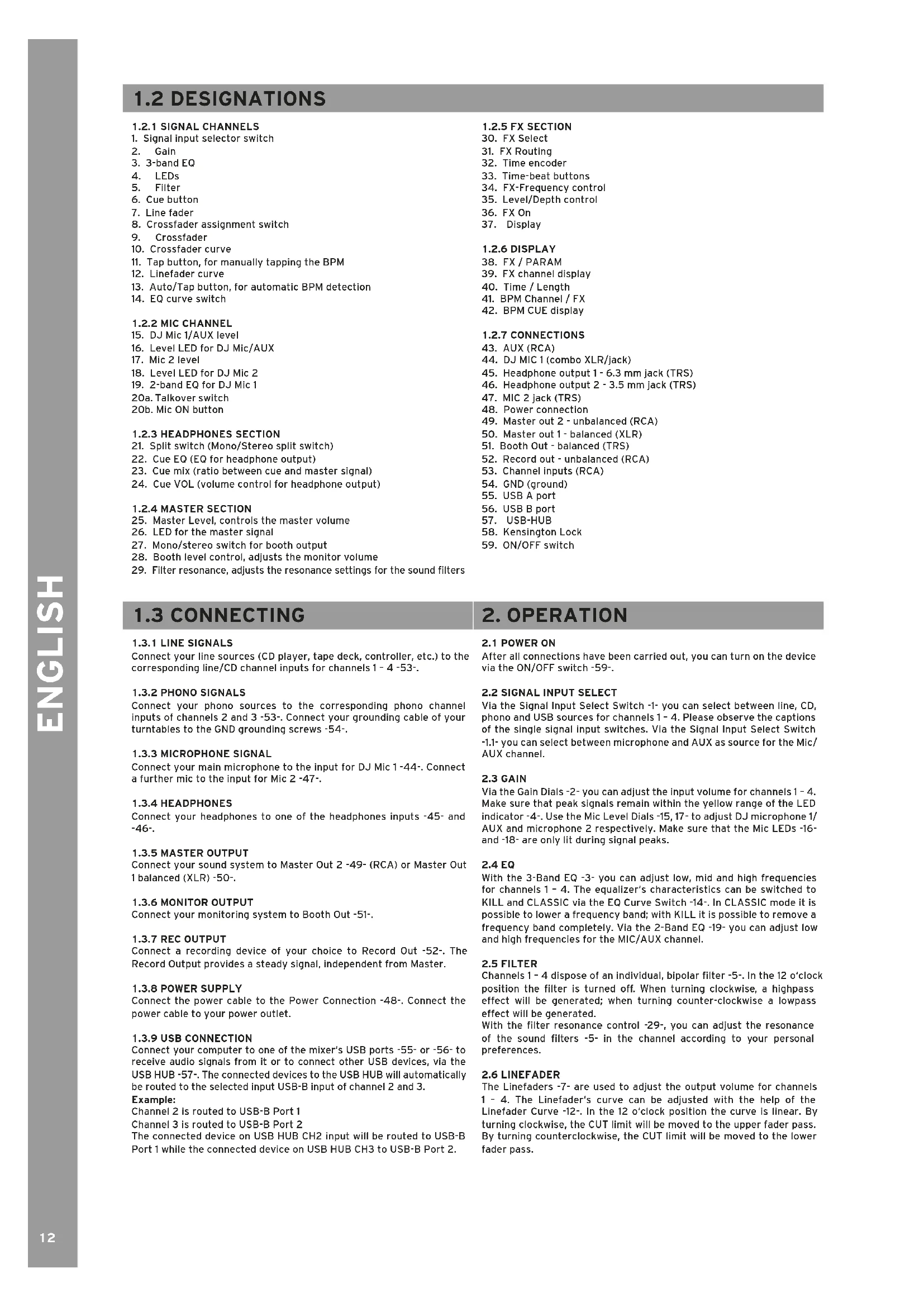
1.2.7 CONNECTIONS
-
AUX (RCA)
-
DJ MIC 1 (combo XLR/jack)
-
Headphone output 1 - 6.3 mm jack (TRS)
-
Headphone output 2 - 3.5 mm jack (TRS)
-
MIC 2 jack (TRS)
-
Power connection
-
Master out 2 - unbalanced (RCA)
-
Master out 1 - balanced (XLR)
-
Booth Out - balanced (TRS)
-
Record out - unbalanced (RCA)
-
Channel inputs (RCA)
-
GND (ground)
-
USB A port
-
USB B port
-
USB-HUB
-
Kensington Lock
-
ON/OFF switch
1.3 CONNECTING
1.3.1 LINE SIGNALS
Connect your line sources (CD player, tape deck, controller, etc.) to the corresponding line/CD channel inputs for channels 1 - 4 -53-.
1.3.2 PHONO SIGNALS
Connect your phono sources to the corresponding phono channel inputs of channels 2 and 3 -53-. Connect your grounding cable of your turntables to the GND grounding screws -54-.
1.3.3 MICROPHONE SIGNAL
Connect your main microphone to the input for DJ Mic 1-44-. Connect a further mic to the input for Mic 2-47-.
1.3.4 HEADPHONES
Connect your headphones to one of the headphones inputs -45- and -46-.
1.3.5 MASTER OUTPUT
Connect your sound system to Master Out 2 -49- (RCA) or Master Out 1 balanced (XLR) -50-.
1.3.6 MONITOR OUTPUT
Connect your monitoring system to Booth Out -51-.
1.3.7 REC OUTPUT
Connect a recording device of your choice to Record Out -52-. The Record Output provides a steady signal, independent from Master.
1.3.8 POWER SUPPLY
Connect the power cable to the Power Connection -48-. Connect the power cable to your power outlet.
1.3.9 USB CONNECTION
Connect your computer to one of the mixer's USB ports -55- or -56- to receive audio signals from it or to connect other USB devices, via the USB HUB -57-. The connected devices to the USB HUB will automatically be routed to the selected input USB-B input of channel 2 and 3.
Example:
Channel 2 is routed to USB-B Port 1
Channel 3 is routed to USB-B Port 2
The connected device on USB HUB CH2 input will be routed to USB-B Port 1 while the connected device on USB HUB CH3 to USB-B Port 2.
2. OPERATION
2.1 POWER ON
After all connections have been carried out, you can turn on the device via the ON/OFF switch -59-.
2.2 SIGNAL INPUT SELECT
Via the Signal Input Select Switch -1- you can select between line, CD, phono and USB sources for channels 1 - 4. Please observe the captions of the single signal input switches. Via the Signal Input Select Switch -1.1- you can select between microphone and AUX as source for the Mic/AUX channel.
2.3 GAIN
Via the Gain Dials -2- you can adjust the input volume for channels 1-4. Make sure that peak signals remain within the yellow range of the LED indicator -4-. Use the Mic Level Dials -15, 17- to adjust DJ microphone 1/ AUX and microphone 2 respectively. Make sure that the Mic LEDs -16- and -18- are only lit during signal peaks.
2.4 EQ
With the 3-Band EQ -3- you can adjust low, mid and high frequencies for channels 1 - 4. The equalizer's characteristics can be switched to KILL and CLASSIC via the EQ Curve Switch -14-. In CLASSIC mode it is possible to lower a frequency band; with KILL it is possible to remove a frequency band completely. Via the 2-Band EQ -19- you can adjust low and high frequencies for the MIC/AUX channel.
2.5 FILTER
Channels 1 - 4 dispose of an individual, bipolar filter -5-. In the 12 o'clock position the filter is turned off. When turning clockwise, a highpass effect will be generated; when turning counter-clockwise a lowpass effect will be generated.
With the filter resonance control -29-, you can adjust the resonance of the sound filters -5- in the channel according to your personal preferences.
2.6 LINEFADER
The Linefaders -7- are used to adjust the output volume for channels 1 - 4. The Linefader's curve can be adjusted with the help of the Linefader Curve -12-. In the 12 o'clock position the curve is linear. By turning clockwise, the CUT limit will be moved to the upper fader pass. By turning counterclockwise, the CUT limit will be moved to the lower fader pass.
2.7 CROSSFADER
With the Crossfader -9- It is possible to switch between the left and right crossfader channel. The crossfader's curve can be adjusted via the Crossfader Curve -10-. By turning counterclockwise, the crossfader becomes "sharp", namely good for scratching and cutting. By turning clockwise, the crossfader becomes "smooth", namely good for long mixes. You can use the Crossfader Assignment Switch -8- to assign the crossfader sides A&B to channels 1 - 4.
NOTE! In THRU position no crossfader side is assigned to the respective channel.
2.8 MICROPHONES
By using the talkover switch -20a- you can activate the talkover effect, i.e. the suppression of the remaining channels by the microphone signal (Active Ducking Technology). In the OFF position the talkover effect is switched off, ON activates the talkover function. With the Mic ON button -20b- you switch on the microphones.
2.9 MONITORING
With the Cue Buttons -6- you can select the input channel(s) that you wish to monitor via your headphones. With Cue Mix -23- you can fade between the channel(s) selected via the Cue Buttons and the master signal. In the CUE position you will only hear the monitoring channels selected via the Cue Buttons; in MASTER position you will only hear the master signal. You can mix the signals steplessly. This way you can simulate a mix via your headphones. With the Cue VOL -24- you can adjust your headphones' volume level. With the Cue EQ -22- you can adjust the headphones signal's acoustic pattern steplessly. In the LOW position the low frequencies will be emphasized, in the HIGH position the high frequencies will be emphasized. Via the Split switch -21- you can select the headphones channel's output mode.
2.10 MASTER SECTION
Use the Master Level -25- to set the master output volume. Make sure that the LED for the master signal -26- is only active in the yellow area. Via the Booth Level -28- you can set the output volume for the Booth output. Use the Mono/Stereo switch -27- to select the output mode of the Booth output.
NOTE! The Rec output -52- is not affected by the position of the volume controls -25- and -28-. See ,Setup Utility 5.2.1 MASTER' for more information and settings.
3. EFFECT UNIT
3.1 OVERVIEW
The RMX-95 disposes of the following high-quality DSP effects with studio quality: Echo, Reverb, Flanger, Phaser, Vinyl Brake, Loop Roll, Noise, Pitch Shift, Delay, Ping Pong Delay, Tap Delay, Bit Crusher and Transformer. Extensive information and parameters are shown on the Display -37-.
3.2 EFFECT SELECT, ROUTING
The selection and routing of an effect always follow the same principle. In the FX / Param -38- the effect names are shown. By turning the FX Select Encoder -30- you can select the effects. Blinking effect names signalize that the respective effect is selected but not yet active. If you press the FX Select Encoder -30-, the currently selected effect will be activated. The active effect's name will now stop blinking -38-. By using the FX Channel Select Switch -31-, the active effect can be assigned to any desired channel (1, 2, 3, 4, Mic, XFA, XFB, Master). The FX Channel Display -39- shows the selected channel as red framed icon. If you have activated the desired effect and assigned it to the desired channel, you can turn the effect unit on or off via the Effect ON/OFF Button -36-. If the effect unit is turned on, the button will shine yellow. Now you can add the effect to the original source signal via the Level/ Depth Dial -35-. Some effect parameters can be manipulated via the Time Encoder -32- or the Time Bar Buttons -33-, respectively. If a Time Bar Button is pressed, the corresponding button will be lit. If the time parameter does not correspond exactly to the specified bar lengths, the two bar values that are between the value will blink. The value adjusted via the Time Encoder -32- or Time Bar Buttons -33- will be shown as bar/milliseconds for tempo-based effects in the Time/ Length Display. Moreover the Time Bar buttons' position will be shown as graphic above the values. If you manipulate a value that has been adjusted via the Time Bar button with the Time Encoder, the Time Bar buttons' position will follow the current value. For details regarding the effects, please refer to the following description.
3.3 EFFECTS
3.3.1 ECHO
The Echo effect produces several copies of the original source signal and adds them to the original signal. Level Depth Adjusts the ratio between effect signal and original signal. On the Effect Display -38- this will be shown as Dry & Wet. 0% stands for no effect. 100% stands for maximum effect setting. Time Encoder Steplessly adjusts the time lag in milliseconds. If you press and hold the Time Encoder, steps of 10 milliseconds will be carried out. (2 ms - 4,000 ms) Time Bar Buttons Gradually adjust the time lag. 1-4; 1-2; 3-4; 1-1; 2-1; 4-1.
3.3.2 REVERB
The Reverb effect produces a stereophonic sound. The original sound seems to move away from the listener. Level Depth Steplessly adjusts the ratio between effect signal and original signal. On the Effect Display -38- this will be shown as Dry & Wet. 0% stands for no effect. 100% stands for maximum effect setting. Time Encoder Adjusts the time lag, namely the virtual room's size in steps of 1. If you press and hold the Time Encoder, steps of 10 will be carried out (1-100). Time Bar Buttons Gradually adjust the time lag, namely the virtual room's size. 1; 10; 25; 50; 75; 90; 100.
3.3.3 FLANGER
The Flanger is a classic DJ effect. First the input signal is divided into signal paths that are then added with a time lag to a mixing step. Level Depth Adjusts the ratio between effect signal and original signal. On the Effect Display -38- this will be shown as Dry & Wet. 0% stands for no effect. 100% stands for maximum effect setting. Time Encoder Steplessly adjusts the time lag of a pass in milliseconds. If you press and hold the Time Encoder, steps of 50 milliseconds will be carried out. (10 ms - 32,000 ms) Time Bar Buttons Gradually adjust the time lag of a pass. 1-1; 2-1; 4-1; 8-1; 16-1.
3.3.4 PHASER
The Phaser effect combines the original signal with a copy that is slightly out of phase with the original. This means that the amplitudes of the two signals reach their highest and lowest points at slightly different times
3.3.5 VINYL BRAKE
Emulates a vinyl stopping effect sound. The length of the effect can be set with the Level Depth knob.
3.3.6 LOOP ROLL
The Loop Roll effect repeats the original signal in the selected length and adds it to the original signal. Level Depth Adjusts the ratio between effect signal and original signal. On the Effect Display -38- this will be shown as Dry & Wet. 0% stands for no effect. 100% stands for maximum effect setting. Time Encoder Steplessly adjusts the loop's length by 1 millisecond. If you press and hold the Time Encoder, steps of 10 milliseconds will be carried out. Time Bar Buttons Gradually adjust the loop's length or trigger the loop. 1-8; 1-4; 1-2; 1-1; 2-1; 4-1.
3.3.7 NOISE
Adding Signal Noise is a popular effect to emphasize certain passages in a track. The RMX-95's noise can also be modulated via LFO to create rhythmic effects. Level Depth Adjusts the noise's 'color'. Time Encoder Steplessly adjusts the LFO's speed by 1 millisecond. If you press and hold the Time Encoder, steps of 10 milliseconds will be carried out. Time Bar Buttons Gradually adjust the LFO's speed. By pressing button 1-4 the LFO will be deactivated.
3.3.8 PITCH SHIFT
The Pitch Shift effect manipulates the original signal's tone pitch. Level Depth Not available. The effect always works at a 100%. Time Encoder Steplessly adjusts the pitch. When turning clockwise, the signal's pitch will sound higher. When turning counter-clockwise, the signal's pitch will sound lower. By pressing the FX Select Encoder -30-, the effect will be reset. Time Bar Buttons Gradually adjust the pitch. Button 1-1 means no pitch. Buttons with higher values make the signal sound higher, buttons with lower values let the signal sound lower.
3.3.9 DELAY
The Delay effect produces a delayed copy of the original source signal and adds it to the original signal. Level Depth Adjusts the ratio between effect signal and original signal. On the Effect Display -38- this will be shown as Dry & Wet. 0% stands for no effect. 100% stands for maximum effect setting. Time Encoder Steplessly adjusts the time lag in milliseconds. If you press and hold the Time Encoder, steps of 10 milliseconds will be carried out. (2 ms - 4,000 ms) Time Bar Buttons Gradually adjust the time lag of a pass. 1-4; 1-2; 3-4; 1-1; 2-1; 4-1.
3.3.10 PING PONG
A Ping Pong Delay is a stereo feedback delay where the delay bounces back and forth between the left and right channels
3.3.11 TAPE DELAY
Tape Delay is a charismatic effect based on the first delay effect devices that were working with an endless tape loop. Level Depth Adjusts the ratio between effect signal and original signal. On the Effect Display -38- this will be shown as Dry & Wet. 0 % stands for no effect. 100 % stands for maximum effect setting. Time Encoder Steplessly adjusts the tone pitch of the repeated signal from 2 ms - 4,000 ms. Time Bar Buttons Gradually adjusts the tone pitch of the repeated signal. -100 - +100
3.3.12 BIT CRUSHER
The bit crusher effect reduces the original signal's quality which leads to a crispy oldschool sound. Level Depth Adjusts the ratio between effect signal and original signal. On the Effect Display -38- this will be shown as Dry & Wet. 0% stands for no effect. 100% stands for maximum effect setting. Time Encoder Steplessly reduces the quality from -100 - +100. Time Bar Buttons Gradually reduce the quality -100 - +100. 100; 50; 10; -10; -50; -100.
3.3.13 TRANSFORMER
The Transformer rhythmically fades the signal in and out. Level Depth Steplessly adjusts the ratio between effect signal and original signal. On the Effect Display -38- this will be shown as Dry & Wet. 0% stands for no effect. 100% stands for maximum effect setting. Time Encoder Steplessly adjusts the time lag between Fade In - Fade Out in milliseconds. If you press and hold the Time Encoder, steps of 10 milliseconds will be carried out. (25 ms - 16,000 ms) Time Bar Buttons Gradually adjust the time lag between Fade In and Fade Out. 1-8; 1-4; 1-2; 1-1; 2-1; 4-1.
3.4 FX FREQUENCY
Selects the frequency range to apply the effect. In center position, the complete range is used.
4. BEATCOUNTER
4.1 CUE BEAT COUNTER
The RMX-95 disposes of two separate beat counters. Beat counter 1 calculates the speed of the channel with activated Cue Button -6-. The calculated speed is shown on the BPM Cue Display -42-. The number blinks while the beat counter is calculating the BPM or when a weak, non-countable or no signal is present.
4.2 CHANNEL/FX BEAT COUNTER
Press the Tap Button -11- at least 4 times to the beat of the music. Now with the activated ON/OFF Button the tempo can be determined for the channel that was selected with the FX Routing selector -31-.
TIP: Please check whether the Effect On/Off Button is turned on or off and put the Effect On/Off Button all the way to the left, if you want to use the beat counter only. In both cases the determined speed is shown on the BPM Channel/FX Display -41- and serves as base for the time calculation of time-based effects. The number blinks while the beat counter determines the BPM or when a weak, non-countable or no signal is present.
NOTE! The RMX-95 disposes of an Intelligent beat counter optimized for a speed range between 80 BPM and 160 BPM. If the beat counter recognizes a speed below 80 BPM (i.e. 70 BPM), it interprets this as double time, namely 140 BPM. And speeds higher than 160 BPM are recognized as half time (i.e. 180 BPM are recognized as 90 BPM). If there is no continuous rhythm structure or the beats do not start out enough to be recognized as rhythm element, the tempo cannot be determined automatically. In this case it is necessary to use the manual beat counter.
5. SETUP-UTILITY
5.1 MENU STRUCTURE
Via the setup menu it is possible to adapt basic system settings to your individual needs. USER SETUP: Hold CF START + CH START-buttons for 3 seconds while the mixer is already powered on. Changes can be applied in real-time. CLUB SETUP: Hold CF START + CH START-buttons while powering on the mixer. The Effect Display -38- will read MASTER. By turning the Beat FX Encoder -30- you can access the various menu items. When you have found your desired menu item, press the Beat FX Encoder. Now you can adjust the menu item by turning the Beat FX Encoder.
5.2 MENU ITEMS
5.2.1 MASTER
Select between stereo and mono. If your sound system only disposes of mono mode, it is recommended to activate mono to make sure that the same signal is sent to all speakers.
5.2.2 LIMITER
The limiter reduces the output signal. Select between a reduction of 0dB, -3dB, -6dB & -12dB. In order not to exceed a certain volume level, it is helpful to limit the maximum output beforehand.
5.2.3 USB OUT
You are able to send various input signals from the mixer to your computer via the USB connections -55- and -56-. Set the respective input switches to the USB A or USB B position.
TÜRNTABLES: Record players
• CDJs: CD players
- Custom: Based on the setting in the USB OUT firmware menu, you can also use different DVS sources (TURNTABLES & CDJs).
USB IN (Mixer Output)
• 1+2: DVS Input Source Deck 1
• 3+4: DVS Input Source Deck 2
• 5+6: DVS Input Source Deck 3
• 7+8: DVS Input Source Deck 4
• 9+10: Master Recording (Mix)
NOTE! Input sources can be selected within the firmware menu.
USB OUT (Mixer Input)
• 1+2: Deck 1
• 3+4: Deck 2
• 5+6: Deck 3
• 7+8: Deck 4
• 9+10: Master (Return)
NOTE! Please visit https://www.reloop.com/faqs/ to find out which DJ software is suitable for DVS use with the RMX-95.
5.2.4 AUX GAIN COMPENSATION
You can increase the Aux Input's input level in order to achieve louder playback of sources with a weaker signal (e.g. smartphones).
5.2.5 PAN / BALANCE
Adjust the left/right balance of the master sound output.
5.2.6 CUE SET
Solo: Only one channel can be selected as cue source. An advantage of this variant is that you only need to switch one cue button.
Mix: Several channels can be selected simultaneously as cue source.
5.2.7 TLKOVR
Talkover determines how much the signal will be suppressed by the mic signal. -6dB, -12dB, -18dB, -24dB
5.2.8 ISO XOVR (ISOLATOR CROSSOVER)
Adapt the EQ's bass and high crossover frequencies to your requirements.
e
5.2.9 MIC BTH (MIC BOOTH)
ON: The mic signal is also sent via the booth output.
OFF: The mic signal is not sent via the booth output.
NOTE! The OFF setting can prevent feedback.
5.2.10 MIC LOW CUT
When turned on, low frequencies (f<80Hz) will be cut off.
5.2.11 BTH SRC (BOOTH SOURCE)
With the help of this function an individual signal can be routed to the booth output.
5.2.12 MIDI
The mixer is able to additionally send MIDI signals. The MIDI function can be turned on/off.
5.2.13 EQ CONTROL
Turns on or off the hardware function of the equalizer-knobs. If off, the knobs only send MIDI.
5.2.14 LED CHECK
All LEDs will be activated in order to check their functionality.
5.2.15 FACT RST (FACTORY RESET)
If you have adjusted a setting that cannot be reversed, you can select this item to bring all settings back to default.
5.2.16 FW UPDT (FIRMWARE UPDATE)
- In order to carry out a firmware update, connect your RMX-95 via USB -55- or -56- to a computer and make sure that your RMX-95 is turned off via the ON/OFF Switch -58-. Hold down the Tap button -11- and Auto/ Tap -13- button while powering on the device. Scroll to FW UPDATE and confirm this item by pressing the TIME ENCODER.
Please regularly check www.reloop.com for RMX-95 firmware updates. Please make sure that the loaded firmware is compatible with your device.
- Download the corresponding update package from the Reloop RMX-95 product site and open it.
- Open the program "ReloopFirmwareUpdate.Jar".
- Select the new firmware file by clicking "Open File" and selecting the included *.bin file.
- Click "Start >". The update will start now.
- After a successful update turn off the Reloop RMX-95.
NOTE! If you feel uncertain about this procedure, let your specialized dealer carry out the update.
5.2.18 ABOUT
Shows the current firmware version.
5.2.19 EXIT
The mixing console starts anew.
Reloop Firmware Updater
×

text_image
RELOOP® www.reloop.comReloop Firmware Updater

Note: Please close all applications and disconnect all other devices.
Click Start to continue.

6. TECHNICAL DATA:
Frequency Range: 20 Hz - 20 kHz +2/-3dB
Inputs: 7x line RCA
2x phono RCA
1x mic combo-XLR/jack
1x mic 6.3mm jack (TRS)
2x USB port
Outputs: master XLR (balanced)
master RCA (unbalanced)
...... booth (TRS) (balanced)
rec RCA (unbalanced)
1x headphones 6.3mm jack
....1x headphones 3.5mm jack
EQ range classic at 70 Hz, 1 kHz, 13 kHz: -26 dB/+9 dB
EQ range isolator at 70 Hz, 1 kHz, 13 kHz: -90 dB (total kill)/+9 dB
EQ range mic at 100 Hz, 10 kHz: -12 dB/+ 12dB
EQ headphones at 100 Hz, 10 kHz: -29dB
Power Source: AC100\~240V, 50/60Hz
Power Consumption: 29 WATTS
Dimensions: 322 x 107.5 x 387 mm
Weight: 6.85 kg
Accessories: .... User Manual
AC Power Cord
USB Cable
SERVICE & SUPPORT:
For technical questions or issues, please check our FAQ or request a support ticket: https://www.reloop.com/faqs/
Reloop
www.reloop.com
Reloop Distribution
Global Distribution GmbH & Co. KG
Schuckertstrasse 28
48153 Muenster / Germany
Fax: +49.251.6099368
Subject to alterations.
Illustrations similar to original product.
Misprints excepted.
ATTENTION!
2.1 MISE SOUS TENSION
5.2.7 TLKOVR (TALKOVER)
5.2.9 MIC BTH (MIC BOOTH)
5.2.11 BTH SRC (BOOTH SOURCE)

Note: Please close all applications and disconnect all other devices.
Click Start to continue.

6. CARACTÉRISTIQUES
.1x Mic combi XLR/jack
.1x Mic jack 6,3mm (TRS)
2x port USB
EQ Range Isolator à 70 Hz, 1 kHz, 13 kHz: -90 dB (total kIII)/+9 dB
EQ Range Mic à 100 Hz, 10 kHz: -12 dB/+ 12dB
EQ Casque at 100 Hz, 10 kHz: -29dB
Source d'alimentation: AC100\~240V, 50/60Hz
text_image
WARNING ELECTRIC CHECK FOR ANY INFORMATION TO BE GENERAL CHECKS. THIS ORDER BEANSY PROCESSED BY RIOLOGY, ENGINEERING, AND DRIVE WORKING. WARNING WEATHER THE RICK OF FIRM AND ELECTRIC SPEAK OR NOT EXCEED YOUR WORKING BY INFORMATION TO BE TRANSFERRED IN PREMIERELINE RMX 95 OFF ON POWER AC IN - 121 59 48 52 49 53 53 53 MST 2 REC LINE CD CH4 PHOMO CD CH3 PHOMO CD CH2 LINE CD CH1 USB INTERFACE SMART LINK ACTIVE USB HUE MSF 1 (BALANCED) BOOT (TRS) USB B USB A 56 55 57 50 51 R L (MONO) C E UK C A E A E E E E E E E E E E E E E E E E E E E E E E E E E E E E E E E E E E E E E E E E E E E E E E E E E E E E E E E E E E E E E The best connection with Part I: of PHEX Notes. Operation is subject to the following instructions: (With necessary return or translation/otherwise) & For order must switch any workforce that has closed and extended. 58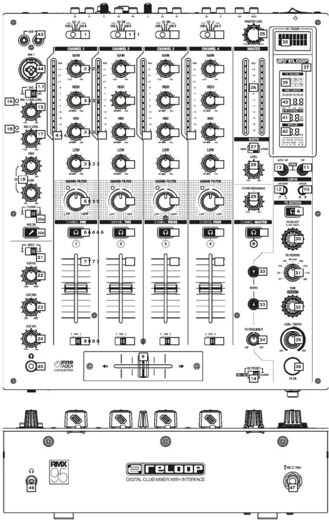
text_image
43 AUX 43 MAC 1 44 SNC 1.1 MNC 1/AUX LEVEL 16 MNC 2 LEVEL 18 MNC 2 17 +0 HIGH 19 LOW TL KINR 20a MUC ON 20b SPLIT ON 21 CUR RQ 22 CUE MIX 23 CUE VEL 24 -00 45 inno FADER compatible 9 A CD LI USB A USB B CD PM USB A USB B CD PM USB A USB B CD PM USB A USB B CD PM USB A USB B CD PM USB A USB B CD PM USB A USB B CD PM USB A USB B CD PM USB A USB B CD PM USB A USB B CD PM USB A USB B CD PM USB A USB B CD PM1.2 DENOMINACIONES
1.2.1 CANALES DE SEÑAL
5.2.7 TLKOVR (TALKOVER)
5.2.9 MIC BTH (MIC BOOTH)
5.2.11 BTH SRC (BOOTH SOURCE)

Note: Please close all applications and disconnect all other devices.
Click Start to continue.

6. DATOS TÉCNICOS
Subject to alterations.
Illustrations similar to original product.
Misprints excepted.