SEW122595.2 - Sewing machine Emerio - Free user manual and instructions
Find the device manual for free SEW122595.2 Emerio in PDF.

| Product Type | Portable Sewing Machine |
| Brand | Emerio |
| Model | SEW122595.2 |
| Power Supply | 4 AA batteries (not included) or 6V 800mA AC adapter (not included) |
| Needle Type | Standard sewing needle No. 14 |
| Bobbin Type | Metal bobbin class 15 |
| Switch | Slide on/off switch |
| Tension Adjustment | Rotary knob to tighten or loosen stitches |
| Thread Guide | Two thread guides + built-in needle threader |
| Base Plate | With center line for straight sewing |
| Handwheel | Manual rotation to position the needle arm |
| Safety | Automatic shutdown when not in use; do not open the casing |
| Cleaning and Maintenance | Unplug/remove batteries before cleaning; do not immerse |
| Intended Use | Household use only, not commercial |
| Warranty | 2 years from date of purchase |
| Customer Service | Emerio B.V., Zomervaart 1A, 2033 DA Haarlem, Netherlands; T: +31(0)23 3034369; info.nl@emerio.eu |
| Dimensions (approx.) | Approx. 25 x 10 x 18 cm (portable) |
| Weight (approx.) | Approx. 0.8 kg (without batteries) |
Frequently Asked Questions - SEW122595.2 Emerio
User questions about SEW122595.2 Emerio
0 question about this device. Answer the ones you know or ask your own.
Ask a new question about this device
Download the instructions for your Sewing machine in PDF format for free! Find your manual SEW122595.2 - Emerio and take your electronic device back in hand. On this page are published all the documents necessary for the use of your device. SEW122595.2 by Emerio.
USER MANUAL SEW122595.2 Emerio
natural_image
White manual hand tool with metal handle and circular button, no visible text or symbols on bodyHandheld Sewing Machine (EN)
Before use make sure to read all of the below instructions in order to avoid injury or damage, and to get the best results from the appliance. Make sure to keep this manual in a safe place. If you give or transfer this appliance to someone else make sure to also include this manual.
In case of damage caused by user failing to follow the instructions in this manual the warranty will be void. The manufacturer/importer accepts no liability for damages caused by failure to follow the manual, a negligent use or use not in accordance with the requirements of this manual.
- This appliance can be used by children aged from 8 years and above and persons with reduced physical, sensory or mental capabilities or lack of experience and knowledge if they have been given supervision or instruction concerning use of the appliance in a safe way and understand the hazards involved.
- Children shall not play with the appliance.
- Cleaning and user maintenance shall not be made by children without supervision.
- This appliance must only be supplied at safety extra low voltage corresponding to the marking on the appliance.
- Switch off or unplug the appliance when leaving it unattended.
- Non-rechargeable batteries are not to be recharged.
- Different types of batteries or new and used batteries are not to be mixed.
- Batteries are to be inserted with the correct polarity.
- Exhausted batteries are to be removed from the appliance and safely disposed of.
- If the appliance is to be stored unused for a long period, the batteries should be removed.
-
The supply terminals are not to be short-circuited.
-
Never run the machine when there's thread in the needle, but no fabric on the machine. This could damage the machine.
- Always keep your hands away from the needle, bobbin, rotary wheel when the appliance is running.
- Never attempt to open the housing of the appliance, or to repair the appliance yourself. This could cause electric shock.
- Never leave the appliance unattended during use.
- Switch off the appliance and take off the batteries/ unplug the appliance before carrying out maintenance.
- This appliance is not designed for commercial use.
- Do not use the appliance for other than intended use.
- Never use the appliance if damaged in anyway.
- Whenever the appliance is not in use make sure it is switched off and the batteries are taken out /unplugged from the power supply.
- Keep the machine in a dry and ventilated place.
- Needle is sharp. Use care when working with needle to avoid injury.
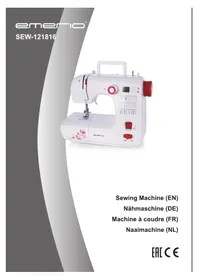
PARTS IDENTIFICATION
- Set screw for needle
- Needle
- Fastening plate
- Tension control
- Thread guide 2
- Needle arm
- Thread guide 1
- On/off switch
- Adapater input
- Battery compartment
- Rotary wheel
- Bobbin
- Extension spindle
- Threader
Note: always use the rotary wheel to move needle arm. Never press or pull directly on the needle arm to avoid damages to the internal mechanism.
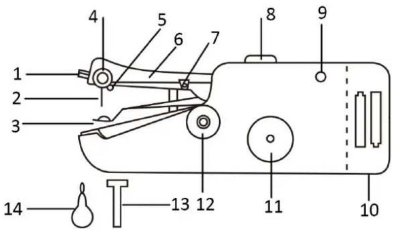
On/off switch: (Fig. 1)
Slide to position A: ON
Slide to position B: OFF
(Fig. 1)
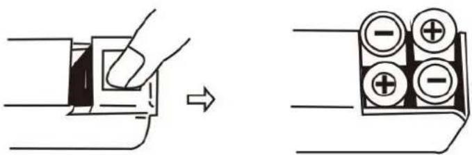
INSTALL THE BATTERIES
- Make sure the "On/off switch" is on the OFF position
- Open the battery compartment cover.
- Insert 4xAA batteries into the compartment and close the battery cover.
Caution:
- To prevent the accidental start-up of the appliance, always make sure that the "on/off switch" is on the OFF position when inserting or removing the batteries.
- When using the adapter, remember to remove all batteries from the machine.
AC/DC ADAPTER (NOT INCLUDED)
Adapter must be 6V 800mA and must use plug with 1/8"/3.5 mm diameter. Plugging an adapter into a socket that has different ratings could damage the socket and adapter.
IMPORTANT NOTES FOR FIRST USE:
When operating the appliance for the first time, you can run the appliance on a test material to get to know well of the operation.
DIRECTIONS FOR USE:
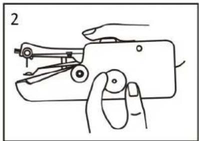
-
Make sure the appliance is in OFF position. Raise the needle arm to the highest position by turning the rotary wheel. Note: the rotary wheel can be turned in either direction. Fig. 2
-
Lift the fastening plate, making sure not to push down on the needle arm (the arm can still be moved manually even when the appliance is in the locked position). Place cloth underneath the fastening plate. Release the fastening plate. Fig. 3
-
Pull at least 2 inches of thread through the needle, from back to front, prior to starting to sew. If the needle needs to be threaded, please refer to "HOW TO THREAD" section.
-
Hold the appliance with right hand. Place thumb by the on/off switch while other fingers support the bottom of the appliance. Fig. 4
natural_image
Line drawing of a hand using a sewing machine to adjust the handle (no text or symbols present)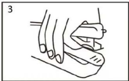
natural_image
Line drawing of a hand holding a small object, possibly a tool or device, with no visible text or symbols.
natural_image
Line drawing of a hand holding a small mechanical device with no visible text or symbols-
Turn the appliance on by sliding the on/off switch forward with the thumb. Use your left hand to hold the cloth and to control the direction and speed as you pull it through the appliance. Be careful not to pull the material through the appliance too quickly. You can follow the centerline on fastening plate to ensure straight stitching.
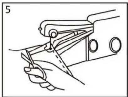
-
When finished sewing, raise the needle arm to the highest position by turning the rotary wheel, then use the back of a seam ripper or scissors to pull the thread out about 3 inches. Cut thread. Fig. 5
-
Lift the fastening plate and take off the cloth. Fig. 6
natural_image
Line drawing of a hand using a sewing machine to cut a garment (no text or symbols present)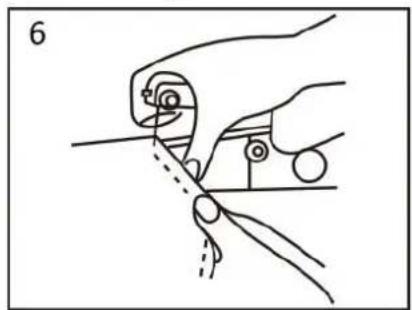
natural_image
Line drawing of a hand holding a tool with a circular component, no text or symbols presentNote:
-
Make sure not to pull the thread. If the reserved 3 inches thread is in the front side of the cloth, when pull the thread, the seam will unravel.
-
The reserved 3 inches thread shall be in the back side of the cloth, if not, please turn to the back side of the cloth, and then pull the thread out to the back side.
-
Tieing a knot in thread
Turn to back side of the cloth and guide the reserved 3 inches of thread according to the following directions and corresponding drawings: Fig. 7
a) Pass the threader through to the last stitch.
b) Put the thread into the threader and pull out about 1 inch.
c) Guide the thread through the loop.
d) Pull the thread tight to finish the knot
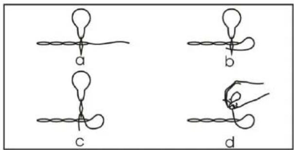
Fig. 7
HOW TO THREAD:
Thread should flow from the top right of the bobbin. Spring must be in place before installing the bobbin. (Fig. 5)
- Pass thread upward through the eyelet of the thread guide 1. From bottom to top.
- Pass thread over top of tension control between the two silver discs.
- Pass thread through the eyelet of the thread guide 2, from front to back.
- Pass thread through the eye of the needle, from right to left. You can use the threader to help you.
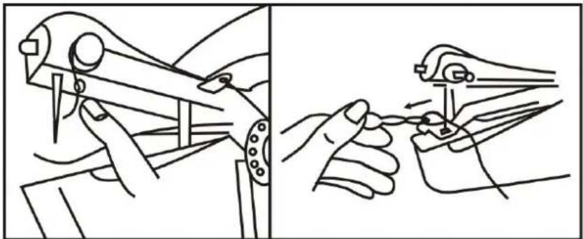
natural_image
Illustration of two hands using a tool to adjust or install a component, showing mechanical assembly and tool path (no text or symbols)Fig. 5
ADJUSTING THREAD TENSION:
- If stitching is too tight, turn tension control slightly to the left.
- If stitching is too loose, turn tension control slightly to the right.
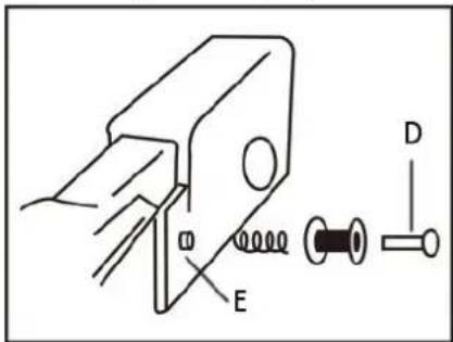
TO REPLACE A NEW BOBBIN
- Lossen the bobbin shaft (D) and take off the used bobbin.
- Slide the new bobbin and the sping into the bobbin shaft. Then connect to the bobbin nut (E).
- When purchasing replacement bobbins for this appliance, please note it uses a class 15 metal bobbin.
TO INSTALL A NORMAL THREAD SPOOL
- Lossen the bobbin shaft and take off bobbin.
- Slide the thread spool into the extension spindle. Do not forget the sping.
- Connect the extension spindle onto the bobbin nut.
TO REPLACE NEEDLE
Loose the set screw with a screwdriver and take off the old needle. Always use a standard sewing machine needle (#14). Needle must be installed with flat side of needle shank facing the front of the appliance.
GUARANTEE AND CUSTOMER SERVICE
Before delivery our devices are subjected to rigorous quality control. If, despite all care, damage has occurred during production or transportation, please return the device to your dealer. In addition to statutory legal rights, the purchaser has an option to claim under the terms of the following guarantee:
For the purchased device we provide 2 years guarantee, commencing from the day of sale. If you have a defective product, you can directly go back to the point of purchase.
Defects which arise due to improper handling of the device and malfunctions due to interventions and repairs by third parties or the fitting of non-original parts are not covered by this guarantee. Always keep your receipt, without the receipt you can't claim any form of warranty. Damage caused by not following the instruction manual, will lead to a void of warranty, if this results in consequential damages then we will not be liable.
Neither can we hold responsible for material damage or personal injury caused by improper use if the instruction manual is not properly executed. Damage to accessories does not mean free replacement of the whole appliance. In such case please contact our service department. Broken glass or breakage of plastic parts is always subject to a charge. Defects to consumables or parts subjected to wearing, as well as cleaning, maintenance or the replacement of said parts are not covered by the warranty and are to be paid.
ENVIRONMENT FRIENDLY DISPOSAL
Recycling – European Directive 2012/19/EU
This marking indicates that this product should not be disposed with other household wastes. To prevent possible harm to the environment or human health from uncontrolled waste disposal, recycle it responsibly to promote the sustainable reuse of material resources. To return your used device, please use the return and collection systems or contact the retailer where the product was purchased. They can take this product for environmental safe recycling.
BATTERY MUST BE RECYCLED OR DISPOSED OF PROPERLY. DO NOT OPEN. DO NOT DISPOSE
OR IN FIRE OR SHORT CIRCUIT.
Emerio B.V.
Zomervaart 1A
2033 DA Haarlem
The Netherlands
Customer service:
T: +31(0)23 3034369
E: info.nl@emerio.eu
SICHERHEITSHINWEISE
natural_image
Simple line drawing of a hand pressing down on a rectangular object with an arrow indicating direction (no text or symbols)
natural_image
Line drawing of a hand holding a small mechanical device with no visible text or symbols
natural_image
Line drawing of a hand holding a small object, possibly a tool or device, with no visible text or symbols.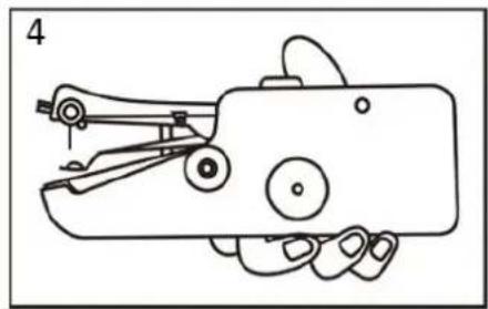
natural_image
Line drawing of a hand holding a mechanical device with no visible text or symbolsnatural_image
Line drawing of a hand using a sewing machine to cut fabric (no text or symbols)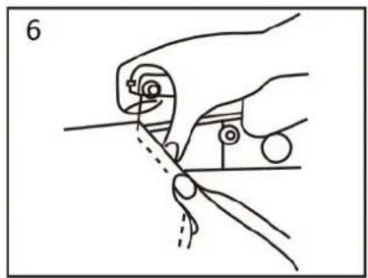
natural_image
Line drawing of a hand holding a tool with a circular component, no text or symbols presentHinweis:
natural_image
Line drawing showing two different manual techniques for using a tool, one being adjusted and the other holding a tool (no text or symbols present)Abb. 5
INSTALLIEREN EINER NORMALEN FADENSPULE
natural_image
Simple line drawing of a hand pressing a button on a rectangular object, with an arrow indicating direction (no text or symbols)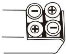
natural_image
Pure electrical connector diagram without any text, numbers, or symbolsADAPTATEUR CA/CC (NON FOURNI)
natural_image
Line drawing of a hand using a sewing machine to adjust the handle (no text or symbols present)
natural_image
Line drawing of a hand holding an object, possibly a tool or device, with no visible text or symbols.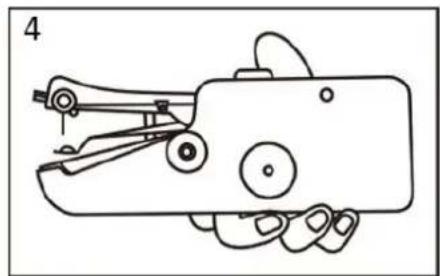
natural_image
Line drawing of a hand holding a small mechanical device with no visible text or symbolsnatural_image
Line drawing of a hand using a sewing machine to cut a piece of scissors (no text or symbols present)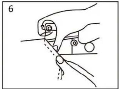
natural_image
Line drawing of a hand holding a tool with a ruler and a pointer, no text or symbols presentRemarque :
natural_image
Illustration of two hands using a tool to adjust or install a mechanical component (no text or symbols present)Fig.5
RÉGLAGE DE LA TENSION DU FIL :
INSTALLATION D'UNE CANETTE ORDINAIRE
natural_image
Simple line drawing of a hand pressing down on a mechanical component with an arrow indicating direction (no text or symbols)
STRÖ MADAPTER (MEDFÖ LJER INTE)
natural_image
Line drawing of a hand using a manual tool to press or install a small mechanical component (no text or symbols)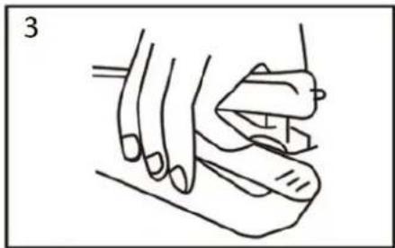
natural_image
Line drawing of a hand holding an object, possibly a tool or device, with no visible text or symbols.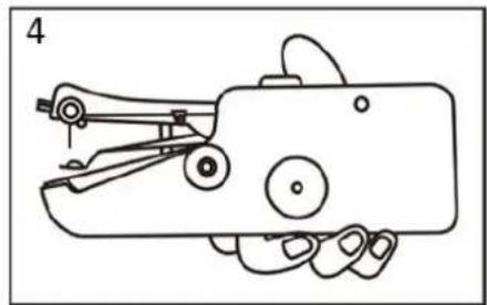
natural_image
Line drawing of a hand holding a small mechanical device with no visible text or symbolsnatural_image
Line drawing of a hand using scissors to cut a piece of paper (no text or symbols present)
natural_image
Illustration of a hand using a tool to cut or wire with a dashed line indicating the process (no text or symbols present)Notera:
natural_image
Line drawing showing two different techniques for using a mechanical tool, one being adjusted and the other holding a tool (no text or symbols present)Bild 5
JUSTERA TRÅ DSPÄNNINGEN
INSTALLERA EN NORMAL TRÄDD SPOLE
natural_image
Simple line drawing of a hand pressing down on a mechanical component with an arrow indicating direction (no text or symbols)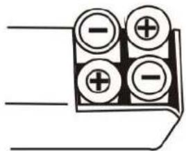
AC/DC-ADAPTER (NIET INBEGREPEN)
natural_image
Line drawing of a hand using a sewing machine to adjust the handle (no text or symbols present)
natural_image
Line drawing of a hand holding a tool, no text or symbols present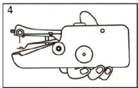
natural_image
Line drawing of a hand holding a small mechanical device with no visible text or symbolsnatural_image
Line drawing of a hand using a sewing machine to cut a piece of fabric (no text or symbols present)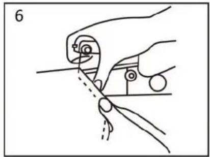
natural_image
Line drawing of a hand holding a tool with a circular component, no text or symbols presentOpmerking:
natural_image
Illustration of two hands operating a mechanical tool, showing hand positioning and tool application (no text or symbols)Fig. 5
EEN NORMALE DRAADKLOS INSTALLEREN
natural_image
Simple line drawing of a hand pressing down on a component with an arrow indicating direction (no text or symbols)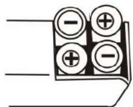
ZASILACZ SIECIOWY (DO DOKUPIENIA OSOBNO)
natural_image
Line drawing of a hand using a manual tool to handle a small mechanical component (no text or symbols)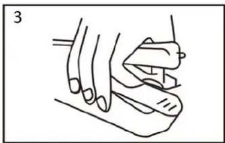
natural_image
Line drawing of a hand holding an object, possibly a tool or device, with no visible text or symbols.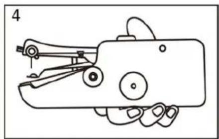
natural_image
Line drawing of a hand holding a mechanical device with no visible text or symbolsnatural_image
Line drawing of a hand using a sewing machine to cut a piece of fabric (no text or symbols present)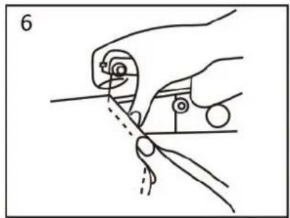
natural_image
Line drawing of a hand holding a tool with a screwdriver, no text or symbols presentUwaga:
natural_image
Illustration of two hands using pliers to adjust or install a tool (no text or symbols present)Rys. 5
REGULACJA NAPREŻENIA NICI:
ZAKŁADANIE NORMALNEJ SZPULKI Z NICIA
natural_image
Simple line drawing of a hand pressing down on a mechanical component with an arrow indicating direction (no text or symbols)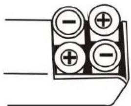
natural_image
Line drawing of a hand holding a small mechanical device (no text or symbols)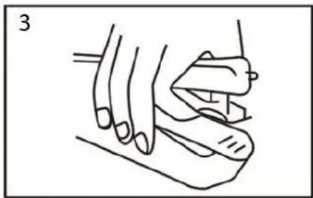
natural_image
Line drawing of a hand holding a tool, no text or symbols present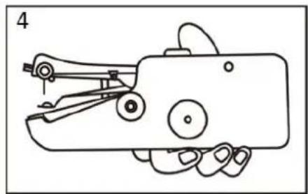
natural_image
Line drawing of a hand holding a small mechanical device (no text or symbols)natural_image
Line drawing of a hand using scissors to cut or draw a mechanical component (no text or symbols)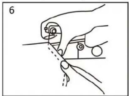
natural_image
Illustration of a hand holding a tool with a ruler and a pointer, no text or symbols presentПримечание:
natural_image
Illustration of two hands using a tool to adjust or install a mechanical component, showing no text or symbols.Рис. 5
natural_image
Simple line drawing of a hand pressing down on a rectangular object with an arrow indicating direction (no text or symbols)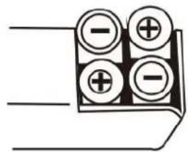
natural_image
Line drawing of a hand holding a small mechanical device with no visible text or symbols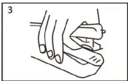
natural_image
Line drawing of a hand holding a small object, possibly a tool or device, with no visible text or symbols.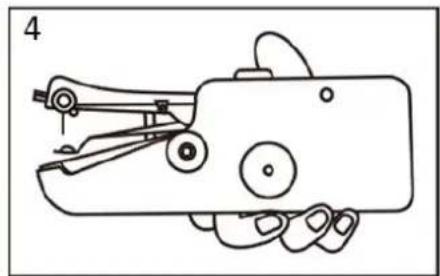
natural_image
Line drawing of a hand holding a handheld device with no visible text or symbolsnatural_image
Line drawing of a hand using a sewing machine to cut a piece of fabric (no text or symbols present)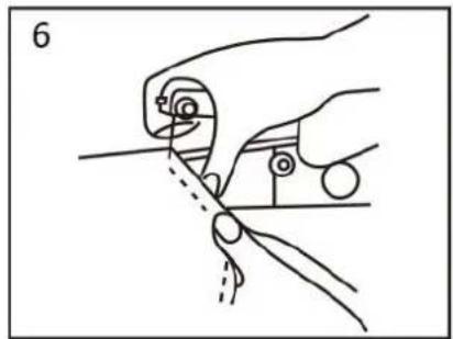
natural_image
Illustration of a hand holding a tool with a circular component, no text or symbols presentNota:
natural_image
Illustration of two hands using a tool to adjust or install a mechanical component (no text or symbols present)(Dibujo 5)
AJUSTE DE LA TENSIÓ N DEL HILO:
CÓ MO INSTALAR UN CARRETE DE HILO
natural_image
Simple line drawing of a hand pressing down on a rectangular object with an arrow indicating direction (no text or symbols)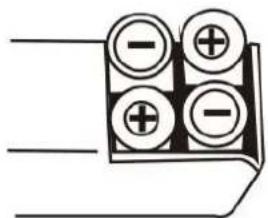
ADAPTADOR AC/DC (NÃO INCLUÍDO)
natural_image
Line drawing of a hand using a sewing machine to adjust the handle (no text or symbols present)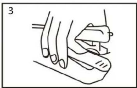
natural_image
Line drawing of a hand holding a tool, no text or symbols present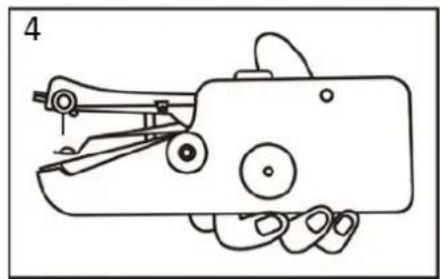
natural_image
Line drawing of a hand holding a small mechanical device with no visible text or symbolsnatural_image
Line drawing of a hand using a sewing machine to cut a garment (no text or symbols)
natural_image
Line drawing of a hand holding a tool with a circular component, no text or symbols presentNota:
natural_image
Illustration of two hands using a tool to adjust or install a mechanical component (no text or symbols present)Imagem 5