Energy Storm 8000E - Generator Lifan - Free user manual and instructions
Find the device manual for free Energy Storm 8000E Lifan in PDF.

User questions about Energy Storm 8000E Lifan
0 question about this device. Answer the ones you know or ask your own.
Ask a new question about this device
Download the instructions for your Generator in PDF format for free! Find your manual Energy Storm 8000E - Lifan and take your electronic device back in hand. On this page are published all the documents necessary for the use of your device. Energy Storm 8000E by Lifan.
USER MANUAL Energy Storm 8000E Lifan
text_image
LIFAN DIRECTOR 3900E DINJALWAL-UL LIFAN STOR4 SERIES Eating Static System Generator 120V DC/DC 50Hz Control panel Control panel Control panel Control panel Control panel Control panel Control panel Control panel Control panel Control panel Control panel Control panel Control panel Control panel Control panel Control panel Control panel Control panel Control panel Control panel Control panel Control panel Control panel Control panel Control panel Control panel Control panel Control panel Control panel Control panel Control panel Control panel Control panel Control panelLF3500 CSA-CA

text_image
STORM SERIES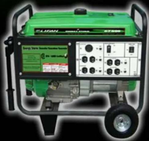
text_image
ELIAN Green Power 67.50V Green Power Sensitive Software P14-12000-LoL/HiLF6500 CSA-CA

CARB / EPA CERTIFIED
text_image
ELIFAN ENERGY STICKER ESICOE Energy Storage System/Server/Server/Server EPA - 0000 LitterLF8000E CSA-CA
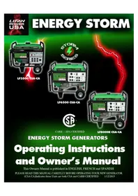
ENERGY STORM GENERATORS
Operating Instructions and Owner's Manual
This Owners Manual is published in ENGLISH, FRENCH and SPANISH
PLEASE READ THIS MANUAL CAREFLLY BEFORE OPERATING YOUR NEW GENERATOR
(CSA-CA)Indicates these Units are both CSA and CARB CERTIFIED 1/12/2015

text_image
LIFAN POWER USA LIFAN LIFAN POWER USA
text_image
STOPTHANK YOU FOR YOUR PURCHASE PLEASE READ!!!!
DO NOT RETURN THIS PRODUCT TO THE STORE
WE ARE HERE FOR YOU! Call Customer Service Toll-Free 1-866-471-7464 Tech Help-Line Open from 9-5 at 866-471-7464 OPTION 2 or visit us online at www.lifanpowerusa.com
NO DEVUELVA ESTE PRODUCTO A LA TIENDA
NE PAS RETOURNER CE PRODUIT AU MAGASIN
NOUS SOMMES ICI POUR VOUS!
(Unique Idener stamped on engine crankcase)
Date of Purchase ____
Purchase Locaon ____
PLEASE KEEP AND READ THIS MANUAL CAREFULLY BEFORE OPERATING YOURNEWPORTABLEGENERATOR
(-CSA-CA)Indicatesth isunitisCSA (Canadian Compliant)
And CARB Cered (California Compliant)
(E) Indicates this unit is Equipped with Electric Start
PLEASE READTHE FOLLOWINGINSTRUCTIONS!
- Unit Shipped with "NO OIL" in Engine or where applicable pumps and/or accessories. Check and II with proper oil as outlined in the Owner's Manual for the respective product.
- For repair under Warranty or quesons concerning Warranty, DO NOT return this product to the Storewhere purchased. Follow the procedures as outlined in the "WARRANTY POLICY" and "WARRANTY REGISTRATION" in the Owner's Manual. For any quesons visit www.lifanpowerusa.comorcall 1-866-471-7464 OPTION 1.
- Read the "Owner's Manual" prior to operan ganyequipment and familiarize yourself with the proper and safe operaon of th eequipment. If you have any quesons visitwww.lifanpowerusa.comorcall 1-866-471-7464.
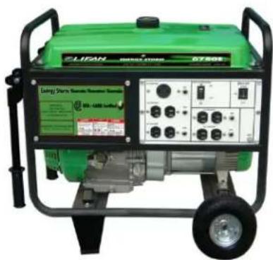
natural_image
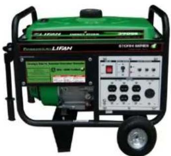
Green industrial power plant with control panel and wheels (no visible text or symbols)LF3500(E)-CSA-CA
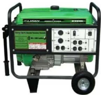
natural_image
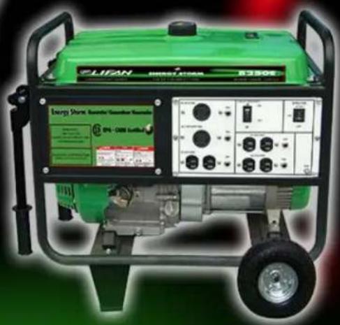
Green portable electricity generator with control panel and wheels (no visible text or symbols)LF6500(E)-CSA-CA
natural_image
Green portable electricity generator with control panel and wheels (no visible text or symbols)LF8000(E)-CSA-CA
(CSA-CA)Indicate this unit is CSA (Canadian Compliant) And CARB Cered (California Compliant)
(E) Indicates this unit is equipped with Electric Start
Table of Contents
Preface 4
Product Specicaons 5
Safety Instrucons 6
Controls and Features 9
Voltage Regulator Switch 11
PRE-OPERATINGINSTRUCTIONS 12
Assembly 14
Baery Specicaons 15
GeneratorSetup 16
Operaon of Generator 19
Storing the Unit 23
Maintenance 24
Troubleshoong/General Safety 29
Generator Waage ReferenceWorksheet 32
Limited Warranty Policy 35
Wiring Diagrams 39
Spanish Version 44
French Version 64

text_image
LIFAN POWER USA LIFAN LIFAN POWER USAPreface
Thank you for choosing LIFAN Power USA for your Power Equipment Needs.LIFAN Power USA prides itself on providing quality products at aordable pricing, creang the "Best Equipment Value on Today's Market!"
All LIFAN Power USA products are manufactured utilizing the latest technology. Built with quality components, your new Power Equipment Product will give you years of dependable service. Your unit, along with all of LIFAN Power USA products are designed, engineered, and manufactured with LIFAN's Industrial Grade Gasoline Engine.
This Owner's Manual will provide you with all of your needed informaon for your new Power Equipment Product, including Safe Operaon and Main tenance of your unit. Please read this Owner's Manual completely and carefully prior to operaon. Keep this Owner's Manual for assistance in the future, such as proper main tenance schedules and ps to prolong the life and effective use of your unit. If you require assistance, please visit our website (www.lifanpowerusa.com) or call toll free 866-471-7464 OPTION 2.
This Owner's Manual contains informaon with respect to the newest products at the me of publicaon. Due to revision and modicaons, the informaon noted in the Owner's Manual might vary from the actual status. This Owner's Manual is subject to change without noce. The copyright of this Owner's Manual belongs to EquipSource, LLC. Any group or individual is forbidden to reprint or copy any of this Owner's Manual without the written consent of EquipSource, LLC.
FOR ALL WARRANTY AND SERVICE RELATED ISSUES/QUESTIONS DO NOT RETURN YOUR UNIT TO THE STORE OR DEALER WHERE THE ITEM WAS PURCHASED.
FOR SERVICE VISIT LIFAN POWER USA'S WEBSITE (WWW.LIFANPOWERUSA.COM) OR CALL 1-866-471-7464 OPTION 2. WE WILL BE HAPPY TO HANDLE YOUR WARRANTY ISSUE OR DIRECT YOU TO THE NEAREST "AUTHORIZED SERVICE CENTER."

text_image
POWERED BY LIFAN CSA-CA-EPA CERTIFIED ENERGY STORM SERIES
text_image
LIFAN POWER USA LIFAN LIFAN POWER USAENERGY STORM PORTABLEGENERATORS
| ModelSize | 3500-CSA-CA | 3500E-CSA-CA | 6500-CSA-CA | 6500E-CSA-CA | 8000E-CSA-CA |
| Voltage | 120 / AC | 120/240V AC & | 120/240V AC & | 120/240V AC & | 120/240V AC & |
| AC SurgeOutput ^1 | 3500Watts | 3500Watts | 6500Was | 6500Watts | 8000Was |
| Rated ACOutput ^2 | 3000Was | 3000Watts | 6000Was | 6000Was | 7000Was |
| Maximum ACAmperage | 26amps @120V | 26amps @120V | 40\5amps @120V | 45amps @120V | 62amps @120V |
| ACCycle | 60Hertz | 60Hertz | 60Hertz | 60Hertz | 60Hertz |
| Regulaon | AVR ^3 | AVR ^3 | AVR ^3 | AVR ^3 | AVR ^3 |
| On/OFF - E-Start Switch | On/O | On/O/Start | On/O | On/O/Start . | On/O/Start |
| 120V 20amp ACReceptacle | 3ea. | 3ea. | 4ea. | 4ea. | 4ea. |
| 120 / 30amp ACReceptacle | 1ea. | 1ea. | 1ea. | 1ea. | 1ea. |
| 120/240 AC 4 prong Receptacle | N/A | N/A | N/A | N/A | 1 ea |
| CircuitProtecon | Master CircuitBreaker | Master CircuitBreaker | Master CircuitBreaker | Master CircuitBreaker | Master |
| Individual Circuit Protectors | 1 ea. 20a - 1 ea. 30a | 1ea. 20a - 1 ea. 30a | 4 ea. 20a - 1 ea. 30a | 4 ea. 20a - 1 ea. 30a | 4ea. 20a - 2 ea. 30a |
ENGINE
| Manufacturer | LIFAN | LIFAN | LIFAN | LIFAN | LIFAN |
| Model | LF168F2M13111Rec oil | LF1682 FD 'IL3111 | LF188FN13111 | LF188FDM13111 | LF190FDM13111 |
| Maximum Horsepower(MHP) | 6.5MHP | 6.5MHP | 13MHP | 13MHP | 15MHP |
| EngineDisplacement | 196cc | 196cc | 388cc | 388cc | 420cc |
| StarngSystem | Recoil | Recoil (Recoil & Electric)^4 | Recoil | Recoil &Electric | Recoil &Electric |
| Fuel TankCapacity | 4Gallons | 4Gallons | 6.5Gallons | 6.5Gallons | 6.5Gallons |
| Fuel TankMaterial | Rust PreventaveCoatedSteel | Rust PreventaveCoatedSteel | Rust PreventaveCoatedSteel | Rust PreventaveCoatedSteel | Rust PreventaveCoatedSteel |
| FuelGauge | Yes | Yes | Yes | Yes | Yes |
| Run Time (@ 50%Load) | 12hours | 12hours | 10hours | 10hours | 8hours |
| Sound Level (@ 7m or23) | 65decibels | 65decibels | 75decibels | 75decibels | 75decibels |
| EngineType | 4'StrokeOHV | 4'StrokeOHV | 4'StrokeOHV | 4'StrokeOHV | 4'StrokeOHV |
| FuelType | Automove GradeUnleadedGasoline | Automove GradeUnleadedGasoline | Automove GradeUnleadedGasoline | Automove GradeUnleadedGasoline | Automove GradeUnleadedGasoline |
| FuelCompliance | 10% EthanolMix | 10% EthanolMix | 10% EthanolMix | 10% EthanolMix | 10% EthanolMix |
| Oil Type &Amount | SAE 10w30w20oz | SAE 10w30w20oz | SAE 10w30w32oz | SAE 10w30w32oz | SAE 10w30w32oz |
| Low Oil ShutoProtecon | Yes | Yes | Yes | Yes | Yes |
| CARBCered | (‘CA )ModelsOnly | (‘CA )ModelsOnly | (‘CA )ModelsOnly | (‘CA )ModelOnly | (‘CA )Model Only |
ACCESSORIES
| Spark PlugWrench | 1 ea. | 1 ea. | 1 ea. | 1 ea. | 1 ea. |
| Mobility/Wheel Kit | N/A | All Models | All Models | All Models | All Models |
| Baery (noncluded) | Not Included | See Baery Chart | Not Included | See Baery Chart | See Baery Chart |
| Comments ^1 = Temporary Power available for no more than 10 seconds ^2 = Power Available for ConnuousOperaon ^3 = Automac VoltageRegulation ^4 = Only (E) Models have Recoil & ElectricStart | |||||

text_image
POWERED BY LIFAN CSA-CA-EPA CERTIFIED ENERGY STORM SERIESSAFETY RULES

This is the safety alert symbol. It is used to alert you to potential personal injury hazards. Obey all safety messages that follow this symbol to avoid possible injury or death.
For your safety read this manual carefully. Becomefamiliar with the proper operaon, care, and maintenance of your Lifan generator.
The safety and alert symbol (A) is used with a signal word (CAUTION, DANGER, WARNING), a pictorial and/or safety message to alert you to hazards. CAUTION indicates a hazard which, if not avoided could be harmful
And might result in minor or moderate injury.
DANGER indicates a hazard which, if not avoided, will result in death or serious injury. WARNING indicates a hazard which, if not avoided, could result in death or serious injury.

WARNING!
Running generator emits carbon monoxide an odorless, colorless, poison gas.
Breathing carbon monoxide can cause nausea or death!
ONLY operate generator outdoors.
Exhaust gas must be prevented from entering conned areas
Direct exhaust window from , doors, ventilation and
Do not operate generator inside or under any buildings.
Operang this ingielerator the compartment of a
Recreational vehicle will likely result in death
Do not use this generator within the generator compartment of a recreational vehicle!

isgeneratordoesnotmeetU.S.CoastGuardRegulation CFR-183andshouldnotbeusedonmarineapplications. eofthisgeneratoronmarineapplicationscouldresultin uryordeath.
A

WARNING!
Rapid recoil of starter cord (kickback) may pull hand and arm forward toward engine at a rapid rate. Breaks bones, bruises, and Fractures may result.
- When starting engine, pull cord slowly until Tension is felt, then pull rapidly to avoid kickback.
- Never start or stop engine with electrical Devices plugged in and turned on. Doing so is hazardous and will damage generator.

Generator produces powerful voltage! Only diversified electrician Connect hookups. Failure to isolate Generator from electrical grid can result in death to utility workers as well as Others.
- When using generator as backup power, notify Utility company. Use approved transfer equipment to isolate generator from electric utility.
- Do Not operate generator while exposed to Rain or other wet conditions.
- Do not handle generator when in contact with water.
• Do not contact bare wires or receptacles. - Inspect all electrical cords for damage and Discontinue from use any damaged or excessively worn cords.
- Do not allow unqualified persons to operate or service generator.
Hazard Symbols and Meanings
Explosion
Fire
ElectricalShoc
ToxicFumes
Hot surface or1ms
Kickback
POWERED BY
LIFAN
CSA-CA-EPA CERTIFIED
ENERGY STORM SERIES

WARNING!
Fuel and its vapors are extremely lammable and explosive.
Fire or explosion can cause severe burns or death.
WHEN ADDING OR DRAINING FUEL
- Turn generator o and let it cool for at least three minutes before removing fuel cap. Loosen cap slowly in order to relieve pressure in the fuel tank.
• Fill or drain fuel tank outdoors. Do not excessively inhale fuel vapors. - Keep away from open ames or sparks and other sources of ignition.
- Do NOT smoke while lling fuel tank.
- Do NOT overll tank. Allow space for fuel expansion.
WHEN TRANSPORTING OR REPAIRING EQUIPMENT
• Transport generator with the fuel valve in the o posion.
• Repair generator with the fuel tank empty or the fuel valve in the o posion.
- Disconnect spark plug wire before transport or service.
WHEN STORING FUEL OR EQUIPMENT CONTAINING FUEL
- Store away from furnaces, stoves, water heaters, clothes dryers or other appliances that have pilot light or other ignition source because they can ignite fuel vapors.
WHEN STARTINGE EQUIPMENT
- Ensure spark plug, muer, air cleaner, and fuel cap are inplace.
- Do NOT crank engine with spark plug removed.
• If fuels spills, wait unl it evaporates before starng engine.
WHEN OPERATING EQUIPMENT
• Do not choke carburetor to stop engine.
- Do not p engine or equipment at an angle, which causes fuel to spill.
• This generator is not for use in marineapplicaons.

CAUTION!
Excessively high operang speeds (engine revoluons) increase the risk of injury and damageto the generator. Excessively low speeds impose a heavy load and will damage generator.
- Do NOT adjust engine speed governor. Generator supplies correct voltage and frequency at designated speed.
- Modifying generator in any way may be dangerous and will void warranty.

WARNING!
While engine is running temperature may exceed 150^ F ( 65^ C). Server burns may occur.
Exhaust heat/gasses can ignite combustibles, structures or damage fuel tank causing a ire.
• Do NOT touch hot surfaces and do avoid exhaust gasses.
- Allow generator to cool before touching.
- Keep at least 7 . (183cm) clearance on all sides of generator including overhead clear.
• Reeve exhaust heat may damage fuel tank causing re.
- Code of Federal Regulaon (CFR) Title 36 Parks, Forests, and Public Property require equipment powered by an internal combustion engine to have a spark arrester, maintained in working order, complying to USDA Forest service standard 5100-1 corlater revision. In the state of Californiaa spark arrester is required under section 4442 of the California Public resources code.
WARNING!

Unintentional sparking can result in ire or electrical shock.
WHEN TESTING FOR ENGINE SPARK
- Do NOT check for spark with the spark plugre moved.
• Use approved spark plug tester.
WHEN REPAIRING OR ADJUSTING GENERATOR
- Disconnect the spark plug wire from the spark plug and place the wire where it cannot contact sparkplug.
CAUTION!
Improper use and care of this generator will cause damage and shorten its lifespan. Failure to follow these actions will void all warranties.
• Use generators only for appropriate and designated purposes.
• The dealer or customer helpline (1-866-471-7464) can instruct you on intended uses.
- Generator must be placed on a level surface.
- Do NOT expose generator to extreme conditions. Excessive dust, moisture, and corrosive vapors will damage unit.
• Cooling slots must be kept clear of debris.
- Do not connect improperly operang devices togenerator.
- Shut o generator and take to a qualified service center if the generator fails to operate properly.

text_image
LIFAN POWER USA LIFAN LIFAN POWER USAControls andFeatures
Read this Owner's Manual completely and carefully before Operang Generator.
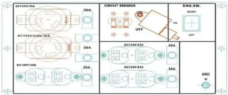
text_image
AC120V/30A 30A CIRCUIT BREAKER ON OFF ENG.SW. START OFF AC120V/240V/30A 30A AC120V/20A 20A AC120V/20A 20A GNDLF8000E CSA-CA

text_image
Energy Storm Generator/Generatur/Generator Distributed by: Lifan Power USA Customer Service 1-868-471-7464 www.lifanpowerusa.com EPA - CARB Certified Equipped with Low Oil Warning System Automatically shot of engine when all need get low DANGER A DANGER DANGER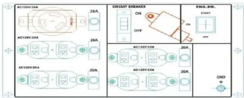
text_image
AC120V/30A 30A CIRCUIT BREAKER ON OFF ENG.SW. START 20A AC120V/30A 20A AC120V/20A 20A AC120V/20A 20A GNDLF6500 and LF6500E CSA-CA
text_image
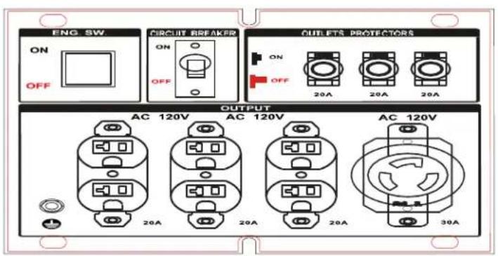
ENG. SW ON OFF CIRCUIT BREAKER ON OFF OUTLETS PROTECTORS ON OFF 20A 20A 20A OUTPUT AC 120V AC 120V AC 120V 20A 20A 20A 30ALF3500 and LF3500E CSA-CA

text_image
POWERED BY LIFAN CSA-CA-EPA CERTIFIED ENERGY STORM SERIES
text_image
LIFAN POWER USA LIFAN LIFAN POWER USA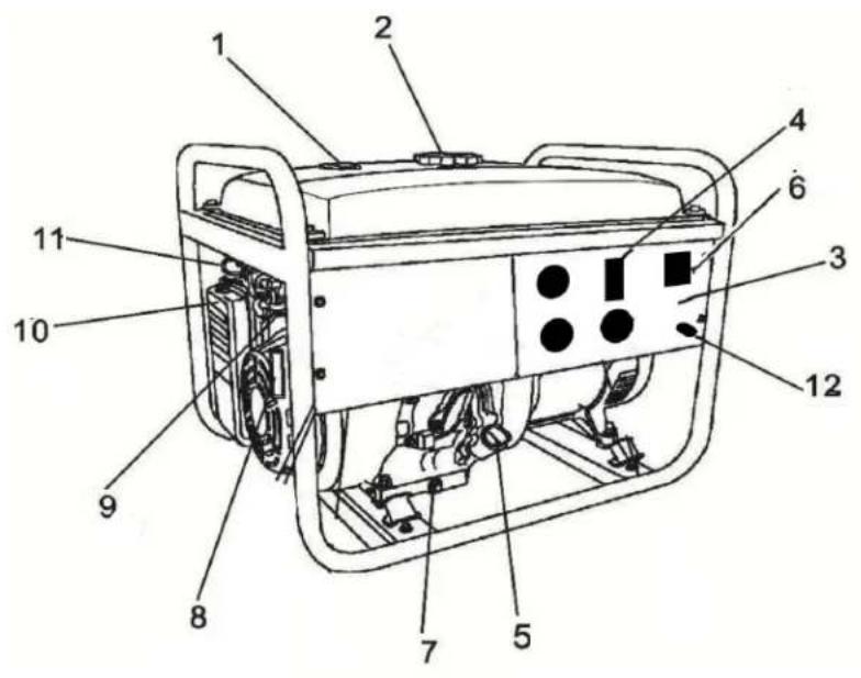
text_image
Technical diagram of a portable gas generator with numbered components for identification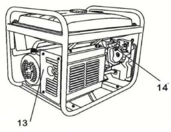
text_image
Technical diagram of a portable gas generator with labeled components 13 and 14Legend
- Fuel Level Sensor – Displays Current Fuel Level
- Fuel Tank Cap – Vented Fuel Cap Must be Properly Installed at all mes during Operaon
- Receptacle Panel – See Product Specicaons for Individual Model
- Double Pole Circuit Breaker (AC) – Protects Receptacles & Generator from Overload
- Crankcase Oil Dipsck/Oil Fill Hole Cap – Check/Fill Engine Oil
- On/O Switch – Rocker Style; Set to "ON" to start Engine & "OFF" to Shut O Engine; Key Switch Model: Turn to "START" to Crank Engine & "OFF" to Shut O Engine
- Crankcase Oil Drain Plug – Remove to Drain Oil from Crankcase
- Recoil Starng Handle – Pull Handle to Rotate Engine for Starng
- Fuel Cock (Valve) – Turn to "OFF" to Terminate Fuel Delivery to Engine
-
Air Cleaner – Check Maintenance Schedule for Service Intervals
-
Choke –
5000 Was & 8000 Was Model: Before starng cold generator, pull the chokepin outward from generator to acvate the choke lever. Aer allowing generator to run for a few seconds, push pin inward toward generator.
3500 Was & 4000 Was Model: Before starng cold generator, rotate the choke lever to the le unl resistance is felt. Aer starng the generator, rotate the choke lever to the right to disengage.
-
Earth Grounding Stud – Always connect generator to an Earth Grounding Source. Consult Local Energy Jurisdiction for Code Requirements in your area.
-
Muer & Muer Hood – Exhaust muer emits combuston gas from engine and lowers the noise level of the generator
-
Valve Cover – Cover for Overhead Valves designed to be removed periodically for valve adjustments.
Voltage Regulator

text_image
LIFAN POWER USA AUTOMATIC VOLTAGE REGULATOR "Constant Quality and Quantity of Voltage" All Lifan Power USA ProSeries and EnergyStorm Generators are equipped with Automatic Voltage Regulators to ensure maximum protection for your appliances as well as your generator. By regulating the level of voltage in an alternating current (AC) system to a narrower range of output, the AVR protects any parts of your systems that might be damaged by surges or drops in voltage or power, particularly during the start-up of your appliances when the maximum voltage and power are required. The AVR ensures a constant quality and quantity of voltage is supplied to protect the appliances and system. "Your Best "Value" on Today's Equipment Market"All Energy Storm Generators are equipped with AVR to get maximum performance and power from your unit.
PreOperangInstrucons: Assembly
Your LIFAN Power USA generator is packaged without fuel and oil. Some assembly is required before operating your LIFAN Power USA Generator.
For further assistance in assembling your generator please visit our website (www.lifanpowerusa.com) or call 1-866-471-7464 opon 2, b between the hours of 9am-5pm Monday-Friday.
BOXCONTENT:
- Generator
-
Accessory Kit
○ 1 ea. ---Spark Plug RemovalTool
o 1ea. --Nema14-30 Male Twist Lock Plug -
Owner's Manual and Warranty Card
- WheelKit (All 6500W & 8000W Models; Only3500 W/Electric Start Models)
- 2ea. - Never-Go-Flat Foam Filled Wheels
○ 2 ea. --- Heavy Duty Leg Supports (Shipped Stored Under FuelTank)
○ 1 ea. --Axle
○ 2 ea. ---Folding Handle
○ Hardware Bag
UNPACKING THEGENERATOR:
- Set the Carton on a Flat, Rigid Surface.
- Remove All Contents from Carton EXCEPT Generator.
- Open Box Completely by Cung Each Corner from Top toBoom.
- Leave Generator on the Remainder of the box unl Wheel Kit is installed.
- Locate all Box Contents and Place them Beside the Generator. (Some Items maybe Packed within the voids of the Generator itself)
Pre-Operang Instrucons: Assembly
WHEEL KITINSTALLATION:
The Following Tools are needed to Install Wheel Kit:
- Safety Glasses
• 8mm-14mmWrench Set
• 8mm-14mmRatchet& Socket Set
• 17mm Ratchet & Socket
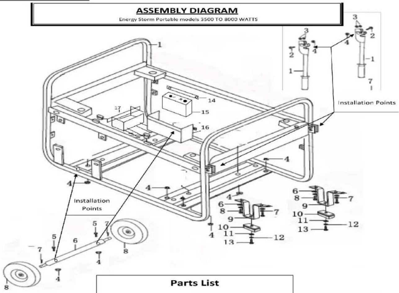
Wheel Kit InstallaonDirecons:
NOTE: Install Wheel Kit BEFORE Filling the Generator with Fuel or Oil. Never Tip a Unit that contains Fuel or Oil.
- Tip Generator so Engine End isup.
- Slide Axle through both Mounng Brackets.
- Place a Wheel on both Sides as shown in "Assembly Diagram."
- Securely Tighten Wheel nuts with the 17mmSocket.
- Tip the Alternator End of the Generator up.
- Place the Support Legs under the Frame Brace as shown in "Assembly Diagram."
- Secure with the provided Cap Screws and Hex Nuts. Securely ghtenusing 12mm Ratchet and Socket.
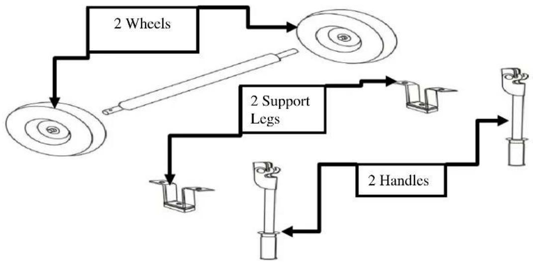
flowchart
graph TD
    A["2 Wheels"] --> B["2 Support Legs"]
    B --> C["2 Handles"]
    C --> D["End"]
    A --> E["Bottom Left Wheel"]
    E --> F["Bottom Right Wheel"]
    F --> G["Bottom Right Hand"]
    G --> H["Bottom Left Hand"]
    H --> I["Bottom Left Wheel"]
    I --> J["Bottom Right Hand"]
    J --> K["Bottom Right Hand"]
Pre-OperangInstrucons: Assembly
text_image
ASSEMBLY DIAGRAM Energy Storm Portable models 3500 TO 8000 WATTS 1 2 3 4 1 2 3 4 -1 7 1 14 15 16 17 4 Installation Points 4 Installation Points 6 8 7 9 10 11 12 13 14 15 16 5 6 7 8 Parts List| 1. | Handle | 2 pcs. | 9 | Front Leg | 2 pcs |
| 2. | Flange bolt 8mm × 45mm | 2 pcs. | 10 | Leg Skid Pad | 2 pcs |
| 3. | Nylon Washers.8mm | 4 pcs. | 11 | Flat washer 6mm | 2 pcs |
| 4. | Nut M8 | 12 pcs | 12 | Spring washer 6mm | 2 pcs |
| 5. | Flange bolt 8mm × 60mm | 2 pcs | 13 | Flange bolt 6mm × 16mm | 2 pcs |
| 6. | Axle | 1 pc. | 14 | Battery hold down strap | 1 pcs |
| 7. | Cotter Pin | 2 pcs | 15 | 12 volt Battery (not included) | 1 pc. |
| 8. | Tire & Wheel Assembly | 2 pcs | 16 | Battery Box 5000- 8000 watt models | |
| 17 | Battery Box 3500 watt models |

CAUTION! Assemble generator before adding fuel or oil.
POWERED BY
LIFAN
CSA-CA-EPA CERTIFIED
ENERGY STORM SERIES

Pre-OperangInstrucons: Baery Specicaons
(Electric Start (E) Models Only)
The Baery is NOT included with your Energy Storm Generator. These units require an Acid Cell Baery. This baery is used in many applicaons, such as lawnmowers, ATV's, motorcycles, etc. and can be found at many retailers and dealers including where you purchased this Power Equipment Product. Use the “Baery Specicaons” chart below to aain the specicaons of the necessary baery. Or, use the “CrossReferenceModels” chart below to match up with the manufacturer's model number with the brand baery available at your local retailer.
| BATTERYSPECIFICATIONS | ||||
| Generator Model | Length( inch) | Width( inch) | Amp(hr s) | DCVoltage (Volts) |
| ES3500 | 5.25in | 3in | 10 | 12V |
| ES6500 | 5.3125in | 3.1875in | 12 | 12V |
| ES8000E | 5.3125in | 3.1875in | 12 | 12V |
| CROSS REFERENCEMODELS | ||
| GeneratorModel | Manufacturer | ModelNumber |
| ES3500 | SuperStart® | CB9B |
| ES6500 | Excide® | 12N12A-4A-1 |
| ES8000E | Excide® | 12N12A-4A-1 |
Note:(-CA)or (E)Modelshave same Ba erySpecificaons
| Warning | |
| Follow all the baery manufactures' warningsforproper installing of your baery in order topreventdamage to personnel orequipment. | |
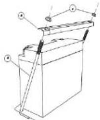
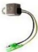
natural_image
Technical line drawing of a battery with mounting points and internal structure (no text or symbols)- Baery leads consist of a Red (hot) lead that connects to the(+) baery post and is connected to the (+) terminal on the starter solenoid and a Black lead which is connected to the(-) nega ve baeryterm inal and the framemounn g bolt.
- Connect the Red (hot) terminal to the baery.
- Connect the Black (negave) terminal to thebaery.
Pre-OperangInstrucons: GeneratorSetup
CAUTION: Any aempt to start the generator before it has been properly serviced may result in engine failure and void warranty.
ADD ENGINE OIL: Refer to the diagrams below.
- Place generator on level surface.
- Clean area around Oil Hole Dipsck/Plug & Unscrew Oil Hole Dipsck/Plug.
- Fill with appropriate type and amount. Refer to Chart below for recommended oil type based on Environmentaltemperature.
NOTE: Refer to "Product Specicaons" secon for universal recommended oil type and oil amount. - Replace Oil Hole Dipsck/Plug and ghten securely.
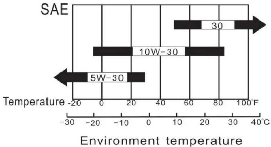
bar
| Range | Temperature Range | | --------- | ----------------- | | 5W-30 | -20 to 30 | | 10W-30 | -20 to 85 |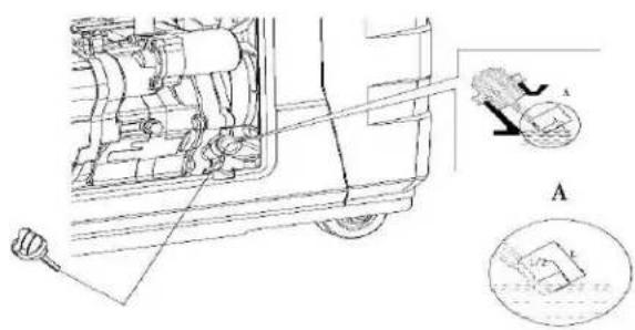
text_image
Technical diagram showing engine components and a mechanical assembly with labeled parts A and BPre-Operang Instrucons: Generator Setup
(Continued)
WARNING!


Fuel and its vapors are extremely lammable and explosive.
Fire or explosion can cause severe burns or death.
WHEN ADDINGFUEL
- Turn generator off and let it cool for a minimum of three minutes before removing fuel cap. Turn and remove capslowly in order to relieve residual tank pressure.
• Always ll the fuel tank with the unit outdoors.
• DO NOT overll tank. Allow room for fuel expansion. - Keep fuel away from sparks, open ames, heat, pilot lights, and other ignition sources.
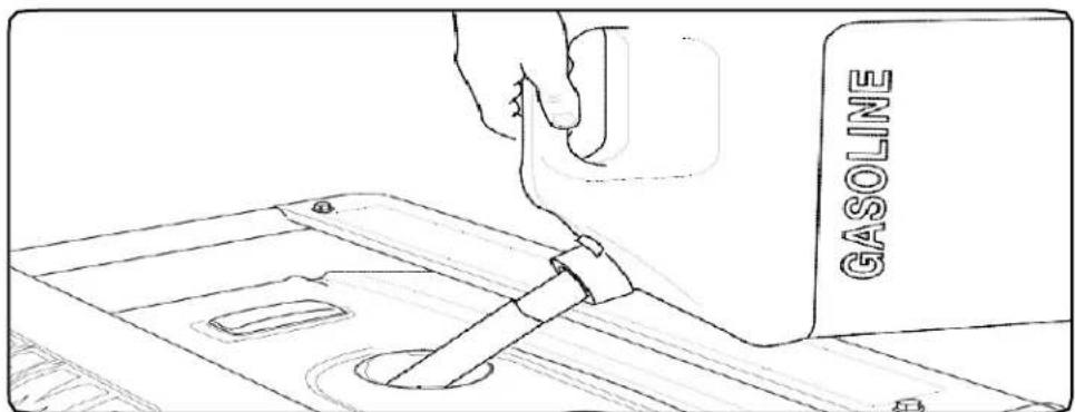
ADD FUEL: Refer to Controls and Features secon for diagrams.
- Clean area around fuel cap, then remove fuel cap.
- Pour fresh, clean regular automove grade unleaded fuel with a minimum octane range of 85 into fuel tank. Do NOT mix fuel with oil. Fuel must have ethanol blend of 10% or less. Pay close aenon to the storage requirements of these fuels. Do NOT overll fuel tank.
- Install the fuel cap. Rotate the fuel cap clockwise until it is in its locked position. Wipe away any spilled fuel.
text_image
GASOLINEPre-Operang Instrucons: Generator Setup
CAUTION:
Alcohol-blended fuels (gasohol, ethanol, or methanol) will aract moisture, which leads to separaon and form aon of acids during storage. Acidic gas can damage the fuel system of an engine while in storage. To avoid engine problems, the fuel system should be treated with a fuel stabilizer or drained if the generator will not be started for thirty (30) days. If using a fuel stabilizer, follow the manufacturer's recommended instrucons for use. Always use stabilizer with a full tank of gasoline.
Always drain old fuel and use fresh fuel before next use. If you do not use a fuel stabilizer, the fuel system must be drained and cleaned. Drain the fuel tank and start the engine, allowing it to run until all fuel lines and carburetor are drained of fuel.
Before restarng the carburetor the oat bowl must be removed and cleaned of any debris.
NEVER use chemical solvents or cleaners in the fuel tank or damage may occur.
CHECK AIR CLEANERELEMENT:
Refer to "Air Cleaner Maintenance" in the Maintenance secon of this Owner's Manual to ensure Air Cleaner Element is in operable condion.
GROUNDING THE GENERATOR:
Refer to Controls and Features secon.
Connect the Ground Terminal on the generator to an acceptable source of electrical ground, such as a copper-grounding stake, using copper electrical wire with a minimum diameter of 16 gauges.
Operaon ofGenerator
HOW TO USE YOURGENERATOR
WARNING!
Running generator gives off carbon monoxide gas. It is odorless, colorless, and highly toxic. Breathing carbon monoxide gas can leads to fainting, nausea or may result in death.
• Only operate generator outdoors.
• Prevent exhaust gas from entering, through windows doors or ventilation intakes, any confined areas.
- DO NOT operate generator inside any enclosed or roofed areas. This includes the generator compartment of any recreational vehicle (RV).
STARTING THE ENGINE: Refer to the Controls and Featuressecon.

CAUTION!
Never start or shut off the generator with electrical loads connected and in the operational mode (on switch activated). Starting or shutting off the generator with electrical loads activated may result in damage to the generator.
- Unplug all electrical loads from the generator.
- Make sure the generator is in a level posion.
- Open the fuel cock by turning the fuel cock to the "ON" posion.
- For cold engine starts only: Pull the choke pin to the engaged posion per the instrucon label on the generator main frame.
PULL START (RECOIL) ONLYMODELS:
- Place the On/O switch in the "ON" (I) posion.
- Grasp starter handle and pull slowly until resistance is felt. Then pull the cord rapidly with a full arm stroke. Allow the rope to return slowly. Do NOT allow the rope to snap back against housing.
- Once the engine runs for 3-5 seconds, push the choke pin in to disengage.
Operaon ofGenerator
HOW TO USE YOUR GENERATOR
ELECTRICT START MODELS:
-
For Electric Start Models, using provided key, turn the key switch to the "ON" posion, for models with the rocker switch start, push the rocker switch to the "ON" posion. Hold key switch in the "START" posion or the rocker switch unl engine starts or for NO MORE than 10 engine rotaons. If the engine does NOT start, wait 15 seconds and repeat starng procedures.
-
Once the engine runs for 3-5 seconds, push the choke pin in to disengage.
NOTE (all models): If generator does not start within FIVE pulls, check the crank case oil level. The engines “Low Oil Alarm System” may be acvated and preventing the engine from starng.
CONNECTING ELECTRICALLOADS:
- Ensure engine is started before plugging in any electrical appliance.
- Plug in desired 120 Volt loads to the 120 VoltU-Ground and 240 Volt loads to the 240 Volt receptacles on the LF8000E model. Always plug appliances into the generator with appliance in its "OFF" posion.
- Do NOT connect 240 Volt loads to the 120 Volt receptacles.
- Only connects single-phase 60 Hertz loads.
- DO NOT OVERLOAD THE GENERATOR. FOLLOW THE PROVIDED "GENERATOR WATTAGE REFERENCE WORKSHEET" TO DETERMINE THE RUNNING AND STARTING WATTAGE OF YOUR EQUIPMENT REFER TO THE PRODUCT SPECIFICATIONS TO ENSURE YOUR GENERATOR WILL OPERATE THE DESIRED EQUIPMENT.
NOTE: Use the running and starng waage provided by the equipment manufacturer if available. If not available, use provided "Generator Waage Reference Worksheet."
Operaon of Generator
HOW TO USE YOUR GENERATOR
LOW OIL ALARMSYSTEM:
This model is equipped with a Low Oil Alert System designed to avoid engine damage from insucient oil in the crankcase. The Low Oil Alarm System will stop the engine automacally before the oil level in the crankcase drops below safe operang levels.
STOPPING THE GENERATOR:
Refer to Controls and Features secon for diagram.
EMERGENCY SHUTDOWN
- Turn the Fuel Valve to "OFF" posion
NORMAL SHUTDOWN
- Unplug all electrical loads or turn the main breaker to the "OFF" posion.
- In order to stabilize internal equipment temperatures, allow the engine to run for 3-5 minutes under no load.
- If the generator will not be in use for more than 7 days, turn the fuel valve to the "OFF" posion and allow the unit to run until the fuel in the carburetor is used and the engine shuts itself o.
- Turn the ignition switch to the "OFF" posion.
- Allow unit to cool to ambient temperature before storage or transportaon.
- Always transport the generator with the fuel valve in the "OFF" posion. Failureto do so will result in damage to the engine.

text_image
LIFAN POWER USA LIFAN LIFAN POWER USAOperaon of Generator
HOW TO USE YOUR GENERATOR
USAGE IN HIGH ALTITUDE REGIONS:
In regions with high altitude e, the standard carburetor produces overly dense combinations of fuel and air, which result in decreased engine performance and increased fuel consumption. To maintain high engine performance at high altitudes, install a high altitude carburetor main spray nozzle and re-adjust the adjusng screw for idle speed. For usage in regions with an altitude of over 4,527ft (1380m), contact your dealer to replace the standard carburetor and make needed adjustments in advance. Even with a proper high altitude carburetor spray nozzle installed in the engine, the power output of the engine will drop about 3.5% with every 1000ft (305m) increase in altitude. If the standard carburetor jets are not replaced and adjusted for usage in high altitude de, the increased altitude de eect will be even more severe.
NOTE: Usage of the generator in regions with lower altitude than the high altitude carburetor spray nozzle is applicable, may result in decrease of engine performance. The engine may become over heated and over-lean combination of fuel and air produced may cause severe damage to the engine.
TRANSFER SWITCH CONNECTIONS - Only allow Professional Electricians
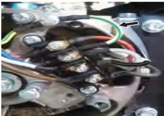
The Lifan EnergyStorm generator is wired with the neutral bonded to ground. If you are connecng your generator to a transfer switch, the electrician must rst determine what type transfer switch is being used. Transfer switches for this equipment are either two-pole or three- pole types.
A two-pole transfer switch will not switch the neutral from the generator to the service panel. That means the generator will be grounded to the service panel. To use the generator with two-pole transfer switches, the electrician will need to change the neutral from bonded to oang.
This is done by removing the jumper wire that connects the alternator ground to the alternator neutral. Remove the jumper wire and reghten the connecons. Keep the jumper wire with the owner's manual in case it is needed for future use when not connected to a transfer switch.
natural_image
Close-up of an automotive engine bay with visible wiring and components (no text or symbols)
text_image
POWERED BY LIFAN CSA-CA-EPA CERTIFIED ENERGY STORM SERIESStoring the Unit
STORAGE
Before long term storage of your power equipment product, typically 30 days or more, perform the following:
- Set the fuel cock (valve) to the "OFF" posion.
- Let the unit connue to run unl it stops itself, burning all of the fuel in the fuel system.
- Turn the ignition switch to the "OFF" posion.
- Drain the engine oil in accordance with the "Oil Change Procedures" in this Owner's Manual's Maintenance secon. Do NOT re-II with oil unl ready to use again.
- Remove the Spark Plug in accordance with the "Spark Plug Maintenance" in the Owner's Manual's Maintenance secon. Spray a lubricant, such as WD40®, into the Spark Plug hole to lubricate the top of the piston and walls of the cylinder. Replace the Spark Plug.
- Pull starter rope unl resistance is felt. This will place the valves in the closed posion.
- Add the recommended amount of fuel stabilizer, in accordance with the amount recommended by the manufacturer of the fuel stabilizer, to the unused gasoline le in the fuel tank.
- Place the unit in a clean, dry, and secure locaon.
- Coverwith "LIFAN WaterProof Generator Cover," Item Number LF100-69600 not included) or canvas/vinyl tarpaulin. Do NOT operate unit with cover installed.
10.
| MAINTENANCE SCHEDULE | |
| PROCEDURE | TIME |
| Engine Oil Check | Each Use |
| Replace Engine Oil | After Each 40 Hours of Use (For Initial Break in – After First (1st) 10 Hours of Use |
| Air Cleaner Filter Check | Each Use |
| Air Cleaner Filter Replacement | When Needed or After Every 50 Hours of Use |
| Air Cleaner Wash | When Needed |
| Spark Plug | When necessary or within 100 hrs. of run time |
| Valve Clearance | Check & Re-adjust annually or after 300 Hours of Use |
| Fuel Tank | Replace Every 3 Years Based on Condion |
Maintenance
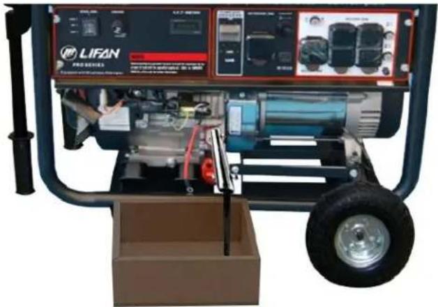
OIL CHANGE PROCEDURES: Refer to Controls and Feature secon for diagram. Periodic Maintenance of your engine oil should be performed aer each 40 hoursof use of you Power Equipment Product. Check your engine oil level prior to each use.
- Start your engine and let it warm up to get the oil warm and thinner. Turn the engine On/OFF switch to the "OFF" posion. Turn Fuel Valve to the "OFF" posion.
- Remove the oil cap/dipsck by turning counter clockwise. Remove the oil drain plug located below the oil cap/dipsck ulizing the appropriate tools.
USE CAUTION: THE OIL MAY BEHOT.
- Drain the engine oil into an approved receptacle and discard in accordance with all Federal and State Regulaons. Never dump the used engine oil on the ground or into drains, only discard in an approved manner. Check with your local authorities to determine the regulaons in your area.
natural_image
Exterior view of a LIFAN PRO-DERIES electric generator with visible control panel and wheels (no text or symbols on main body)Maintenance
WARNING! AVOID SPLASHING OF HOT OIL; IT CAN BURN YOU AND CAUSE SEVERE INJURY.
- After oil is completely drained, replace oil drain plug and ghten with appropriate tools. Replace oil with the proper oil for your product. Refer to the Pre-Operan g Instru con : Generator Setup secon fo r exact ll requirements.
Always use your dipsck to check the oil level and only ll to the full mark on the dipsck. Never overll the engine as this can cause damage to the unit and void warranty.
- Replace the dipsck/oil cap on the engine.
- Shake generator to ensure the oat in the Oil Alert System is free.
PROPER MAINTENANCE OF THE UNIT WILL INCREASE THE LIFE OF YOUR PRODUCT. THE OIL MUST BE CHANGED ON A REGULAR BASIS FOR PROPER OPERATION, AND RELIABILITY AND TO ALSO MAINTAIN THE WARRANTY ON THIS PRODUCT.
AIR CLEANER MAINTENANCE:
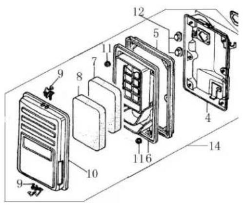
- Remove the clip (item 9 in "Air Cleaner A" below) or the wing nut (item 7 in "AirCleaner B" below) to remove and check the air lter element.
- For Sponge Type Air Filters, wash with soap and water when contaminated. Squeeze excess liquid from air liter element, and allow the air liter element to dry. Lubricate with a few drops of oil. For Paper Type Air Filters, replace with the correct Air Filter for your unit. They are available at your dealer or from LIFAN Power USA. Order your liter by calling toll free 866-471-7464.
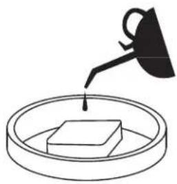
natural_image
Simple line drawing of a container with a lid and a handle, no text or symbols present
natural_image
Simple line drawing of a hand holding a circular object (no text or symbols)
text_image
LIFAN POWER USA LIFAN LIFAN POWER USAMaintenance
- Re-Install the air I ter element into the air I ters housing.
text_image
Exploded view diagram of a device showing numbered components for assembly or maintenance reference.Air Cleaner A Air Cleaner
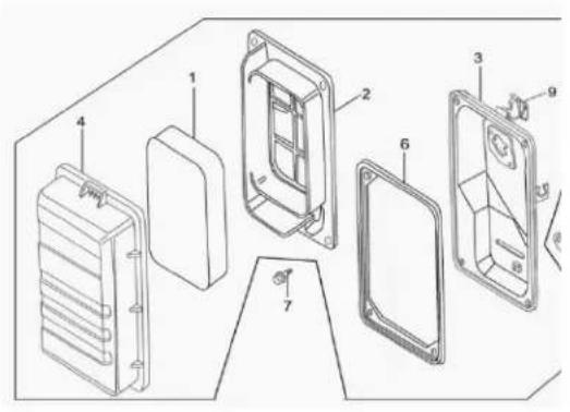
text_image
Technical diagram of a device's internal components with numbered parts, likely for assembly or manufacturing documentation.Maintenance
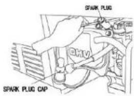
SPARK PLUG MAINTENANCE:
- Remove Spark Plug Cap (refer to "Spark Plug Cap Removal" gure below.)
- Remove Spark Plug with socket and handle supplied with your unit (refer to "Spark Plug Removal" gure below.)
- Clean any carbon build-up around the Spark Plug.
- Check the Spark Plug Gap and adjust if necessary. 0.30-inch gap.
- Lubricate the threads of the Spark Plug with an -seize compound or engine oil.
- Re-install the Spark Plug and Spark Plug Cap.

natural_image
Simple line drawing of a robot with a thought bubble showing a mechanical component (no text or symbols)Spark Plug Cap Removal
natural_image
Close-up of mechanical components with no visible text or symbols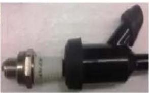
natural_image
Close-up of a black mechanical component with metallic ends and a handle (no visible text or symbols)Spark Plug Removal
text_image
SPARK PLUG SPARK PLUG CAPFUEL SYSTEM MAINTENANCE:
NOTE: Periodically you can get sediment or trash in your Carburetor Bowl. Use the following procedures to clean:
- Turn the fuel cock (valve) to the "OFF" Posion.
- Remove the carburetor bowl by removing the moung bolt located at the boom of the bowl.
- Dump out the old fuel and sediment into an approved container and clean carburetor bowl thoroughly.

text_image
LIFAN POWER USA LIFAN LIFAN POWER USAMaintenance
FUEL SYSTEM MAINTENANCE (connued):
- Fit a new rubber washer into place and re-aac h fuel bowl to the carburetor.
diagram below) and either dean orreplace the fuel I ter element. Re-assemble the fuel I ter element (refer to "Fuel Filter Element Assembly" diagram below.)
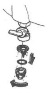
natural_image
Illustration of a hand holding a small mechanical component with multiple parts stacked vertically (no text or symbols)
natural_image
Illustration of a hand holding a valve with internal components, no text or symbols presentFuel Filter Element Removal Fuel Filter Element Assembly

text_image
POWERED BY LIFAN CSA-CA-EPA CERTIFIED ENERGY STORM SERIESTroubleshoong
IF THE ENGINE WILL NOTSTART:
- Check to ensure switches are in the "ON" posion. (Both unit and engine)
- Check engine oil level. Your unit possesses a Low Oil Alarm System that will not allow your engine to start if the oil is below safe operang levels. This featureis installed to increase the life of your engine and prevent engine damage. If oil level is low, ll to the full mark on dipsck. Refer to the Product Specicaons for exact oil type and amounts.
- Check the fuel level to insure adequate fuel. Add fuel if necessary.
- Remove and inspect the spark plug for cleanliness and proper electrode gap. If needed, clean or replace the spark plug. Refer to Spark Plug Maintenance in the Maintenance secon of the Owner's Manual for proper procedure.
- If your unit will sill NOT start after performing the above checks, call our customer hotline at LIFAN Power USA Toll Free 1-866-471-7464 OPTION 2.
NOTE: Periodically on the initial start-up or after the unit has been stored for a long period of me, the o at for the "Low Oil Alarm System" will s ck to the boo m of your oil pan. Locate thetwo (2) wires to the Low Oil Sensor Diode (refer to gure on the right) located on the side of the engine block. Unplug these wires and, only aer e nsuring the engine is full of oil, start the engine and allow running unl warm (normally 20minutes, as this will heat the oil and release the o at on the Low Oil Alert System). Then re-plug the wires to the terminals on the Low Oil Alarm SendingUni
UNIT DOES NOT PROVIDE ELECTRICAL CURRENT:

text_image
Diagram showing four labeled mechanical components with numbered parts, likely illustrating a sequence or assembly.- Plug in a small appliance or tool to test.
- On 2. O/Tripped 3. On 4. O
- Check if the AC (or DC) Circuit Breaker is in the "ON" posion. If no t, place in "ON" posion. If equipped with a GFCI receptacle, re-set GFCI Breaker by pushing in the reset buon in th e middle of the GFCI's face plate (this must be done with the engine running).
- If your unit sll do es NOT produce electricity after performing the previous checks, call LIFAN Power USA at 1-866-471-7464, OPTION 2.
UNIT DOES NOT PROVIDE ELECTRICAL CURRENT (connued):
- If your unit sll do es NOT produce electricity after performing the previous checks, call LIFAN Power USA at 1-866-471-7464 OPTION 2.

text_image
LIFAN POWER USA LIFAN LIFAN POWER USAGenerator Safety
- Never operate gasoline engine powered products in any enclosed spaces, as they product deadly Carbon Monoxide Poisonous Gases.
- Never hook a generator directly to your home circuit without the proper installaon by a Licensed Electrician and without the proper power transfer devices.
- Do NOT operate your power equipment in inclement weather such as rain, snow, and/or sleet.
- Do NOT operate your power equipment within ve (5) feet of any ammable materials.
- When refueling the power equipment never smoke or refuel near any flame or ignition devices. Never refuel while the unit is running. If during the refueling process some fuel is spilled, always completely clean the fuel and allow sufficient drying me prior to re-staring the unit. Gasoline vapors ignite easily and are very dangerous.
- Do NOT parallel connect this model. Generator cannot be combined with other electric wires or mulple socket boxes.
- Do NOT lengthen the exhaust pipe or vent it with any extension.
- Use SJ or SJO type extension cords if necessary.
- Do not use extension cords exceeding: 16 Gauge, 200 or 10 Gauge, 330.
- NEVER ALLOW CHILDREN OR ANIMALS TO BE NEAR THIS EQUIPMENT DURING OPERATION. ONLY QUALIFIED PERSONS SHOULD OPERATE THIS EQUIPMENT. FOLLOW ALL GUIDELINES CONTAINED IN THIS OWNER'S MANUAL FOR THE SAFE OPERATION OF THIS EQUIPMENT.

text_image
DANGER Using a generator inside CAN KILL YOU IN MINUTES Generator exhaust contains carbon monoxide. This is a poison that you cannot see or smell. NEVER use inside a home or garage, EVEN IF doors and windows are open. Only us OUTSIDE and far away from windows, doors, and vents Avoid other generator hazards, READ MANUAL BEFORE USE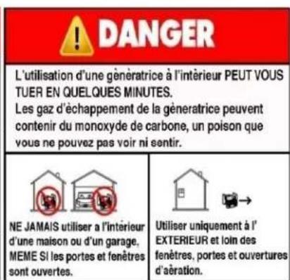
CONVERTING AMPS OR HORSEPOWER INTO WATTS
Was = Amps x Volts
Running Was* = Horsepower x 932** (for motors)
- Add a 10% correcon factor to your totals to help overcome this uncertainty.
If your customer plans to operate devices that use electric motors, list both the starng and running requirements of each.
- Starng requirements of some devices maybe significantly higher than their running requirements. This higher demand must be considered when esmang your power needs. Some small, universal motors — which do not draw a heavy starng load (drills, small saws, blenders, etc.) — require very lile extra current for starng.
| MOTOR/DEVICE | STARTINGWATTS | RUNNINGWATTS |
| Motor A | 2,600 | 850 |
| Motor B | 1,300 | 600 |
| Motor C | 1,000 | 750 |
NO ELECTRIC MOTORS
If your list does not include any devices that use electric motors, simply add the power (running) requirements of all the items on your list to obtain the maximum power needed.
| DEVICE | WATTS |
| Electric Skillet | 1,500 |
| Light | 100 |
| Heang Pad | 65 |
| Total: | 1,665 |

text_image
LIFAN POWER USA LIFAN LIFAN POWER USALIMITED WARRANTY POLICY
This warranty is limited to the following Lifan Power and Storm Series products that are distributed by the EquipSource LLC, dba LIFAN POWER USA, located at 2205 Industrial Park Road, Van Buren, AR 72956. Eecve date is 1-1-2015.
| LENGTH OF WARRANTY | ||||
| Residential Use** | Commercial/Rental*** | |||
| PRODUCTS COVERED | 1^st Year | 2^nd Year | 3^rd Year | Warranty not to exceed 300 hrs. Or terms listed below. |
| Water Pumps | Full unit parts and labor | Full unit parts only | Engine: parts only | Full unit: 12 months parts and labor |
| Generators/Inverter Generators | Full unit parts and labor | Full unit parts only | Engine: parts only | Full unit: 12 months parts and labor |
| Pressure Washer's | Full unit parts and labor | Full unit parts only | Engine: parts only | Full unit: 12 months parts and labor |
| Gasoline Engines | Full unit parts and labor | Full unit parts only | Engine: parts only | Full unit: 12 months parts and labor |
** Residenal Use is dened as items that are for personal use.
*** Commercial/Rental use is denied as any usage for income producing or other business related uses.
In order to qualify for the limited warranty the product(s) must be purchased in North America from an authorized EquipSource, LLF d/b/a Lifan Power USA dealer or a dealer authorized by EquipSource to sell Lifan products. This warranty is non-transferable and applies only to the original purchaser. The supplied "Warranty Registraon Card" must be completed and on le with American Warranty Service (at the supplied address), at the me that any warranty claim is made. The "Warranty Registraon Card" must be submitted with a receipt of purchase which clearly states the date of purchase and where the purchase was made.
During the warranty period (stated above) EquipSource, LLC and/or American Warranty Service will repair or replace, at its' opon, any part that is proven to be defective in material or workmanship under normal usage. Repairs and/or replacement will be made without charge for parts or labor. All parts found to be defective must be returned to EquipSource or American Warranty Service at our direcon. Upon recepon of the parts a judgment as to the validity of the warranty claim will be determined. All parts replaced under warranty or any replacement of the complete unit will be considered part of the original product and replacement of any product, and any warranty on those parts or replacement unit will coincide with the original warranty.
To obtain Warranty Service, call our Customer Service Hotline at 1-866-471-7464 and press 2 for Warranty Service at which me you will be transferred to the technicians at American Warranty Service. In lieu of this you may call directly to American Warranty Service at 888-926-4313 to be directly connected to a repair specialist. If your issue cannot be resolved through consultaon with our customer service representatives, you will be directed to an Independent Service Center of your choice nearest your locaon. Any manufacture's Defects of your product will be repaired or replaced at no charge to you per our commitment. If the issue with your unit is not a Manufacture's Defect, you will be advised to make payment to the Service Center upon diagnosis of repairs which are not covered under the Manufacturer's Warranty Policy. In this case the end user is responsible for all shipping and handling charges associated with the exchange and as stated above the warranty will coincide with the date of the original purchased unit.
This warranty is not valid for products or parts aected or damaged by accident, collision, normal wear, fuel contaminaon, abuse, neglect, misuse, alteraon and/or unsuitable use or unauthorized parts replacement. Mower decks and blades are specially not warranted for impact or abrasive damage. Warranty becomes void if the customer fails to install, maintain, and/or operate the product in accordance with the instrucons and recommended actions of Lifan set forth in the owner's manual. EquipSource, LLC disclaims any responsibility for time loss or loss of usage of the product, transportaon, commercial loss, or any other incidental or consequential damage. Prior to any warranty service an approval code must be issued to the service center in order for the warranty claim to be valid. Any implied warranties are limited to the duraon of this written limited warranty. This warranty gives you specific legal rights, and you may also have other rights, which may vary from state to state.
OWNER'S RESPONSIBILITY
To ensure trouble free warranty coverage it is important that you register your Lifan generator by phone at 1-866-471-7464, or by lling out and returning to Lifan Power USA the warranty registraon card supplied with your generator. Registering your product
This conrms your warranty coverage and provides a direct link between you and Lifan Power USA if we nd it necessary to contact you.
Your receipt for purchase including date, model and serial number must be maintained and registered to receive service from an Authorized Service Dealer for warranty service. Proof of purchase rests solely with you, the original purchaser.
You must demonstrate reasonable care and use, and follow preventive maintenance, storage, fuel and oil usage as prescribed in the operator's manual for your Lifan Power unit. For the warranty assistance from a Lifan Authorized Service Dealer nearest to you, call Lifan's automated phone at 1-866-471-4764 Opon 2. Should you require assistance or have quesons concerning Lifan Power USA Warranty Statement, you can contact us through the web at www.lifanpowerusa.com or call toll free 1-866-471-7464.

text_image
POWERED BY LIFAN CSA-CA-EPA CERTIFIED ENERGY STORM SERIESEXCLUSIONS
- Lifan Power Equipment that ulize non-Lifan replacement parts.
- Failure to perform "Periodic Maintenance" as required and specied in the supplied "Owner's Manual."
• Costs of normal maintenance and adjustments. - Failures caused by any contaminated fuels, oils, or lack of proper oil levels.
- Repairs or diagnoses performed by individuals other than Lifan authorized dealers not authorized in wring by Lifan.
- Failures due to normal wear and tear, accident, misuse, abuse, negligence or improper use.
- Damage related to any animal infestaon to include rodent and/or insect infestaon.
- Products that are modified or altered in a manner not authorized in wring by Lifan.
- Failure due to misapplicaon.
- Telephone, cellular phone, facsimile, internet access, or other communicaon expenses.
- Expenses related to "customer instrucon" or troublesomeong where no manufacturing defect is found.
• Overnight freight or special shipping costs for replacement part(s).
• Overme, holiday or emergency labor.
• Starng batteries, fuses, light bulbs and engine uids.
- As withall mechanical devices, the Lifan engines need periodic part(s) service and replacement to perform as designed. This warranty will not cover repair when normal use has exhausted the life of a part(s) or engine.
- Failures caused by any external cause or act of God, including but not limited to, collision, the, vandalism, riot, war, re, freezing, lightning, earth-quake, windstorm, hail, water, ood, tornado, or hurricane or any occurrence outside of normal use and activity.
- Any incidental, consequential or indirect damages caused by defects in materials or workmanship, or any delay in repair or replacement of the defective part(s).
DISCLAIMER OF IMPLIED WARRANTIES
This limited warranty is in lieu of all other expressed or implied warranes, including any warranty of the unit's tness for any parcular use and any implied warranty of MERCHANTABILITY otherwise applicable to Lifan Power Equipment and its aliated companies shall not be liable for any special, incidental or consequential damage, including lost prots. There are no warranes extended other thanas provided herein. This limited warranty may be modified only by Lifan Power USA. Any implied warranes allowed by law shall be limited in duraon to the terms of the express warranty provided herein. Some states do not allow limitations on how long an implied warranty lasts, so the above limitaon may not apply to you. Some states do not allow the exclusion or limitaon of incidental or consequential damages, so the above limitaon may not apply to you. This warranty gives you spec legal rights. You also have other rights from state to state. Lifan's ONLY LIABILITY SHALL BE THE REPAIR OR REPLACEMENT AS STATED ABOVE. IN NO EVENT SHALL Lifan BELIABLE FOR ANY INCIDENTAL OR CONSEQUENTIAL DAMAGES, EVEN IF SUCH DAMAGES ARE A DIRECT RESULT OF Lifan's NEGLIGENCE. Some states do not allow the exclusion or limitaon of incidental or consequential damages, so the above limitation may not apply to you. This warranty gives you spec legal rights and you may also have other rights from state to state.
OWNER'S WARRANTY RESPONSIBILITIES:
As the outdoor equipment owner, you are responsible for performance of the required maintenance listed in your owner's manual. EquipSource, LLC d/b/a Lifan Power USA recommends that you retain all receipts covering maintenance on your outdoor equipment. Lifan Power USA will not deny your warranty coverage based solely on your lack of receipts for service however, the condition of the equipment upon arrival at the service center will determine the warrantable nature of the product.
As the outdoor equipment owner, you should however be aware that Lifan Power USA may deny your warranty coverage if your outdoor equipment or a part has failed due to abuse, neglect, or improper maintenance or unapproved modicaons.
If you have any quesons regarding your warranty rights and responsibilities, you should contact Lifan Power USA or American Warranty Service Representave at 1-866-471-7464 Opon 2 Warranty and Service or at the following address Lifan Power USA, 2205 Industrial Park Road, Van Buren, AR 72956 or by contactng us through www.lifanpowerusa.com.
This warranty specifically excludes the use of any Lifan Power Equipment or Storm Series power equipment as the "Sole Source of Power" for "o the power grid applicaons" and this warranty will become null and void for units used for this purpose and manner. This warranty specially excludes the use of any Lifan Power Equipment or Storm Series power equipment for the purpose of powering Life Support devices, Life Support appliances, Medical devices, and/or Medical appliances. EquipSource, LLC will not be held responsible for any damage due to the use of any Lifan or Storm Series power equipment for these purposes.

text_image
LIFAN POWER USA LIFAN LIFAN POWER USAAPPENDIX

text_image
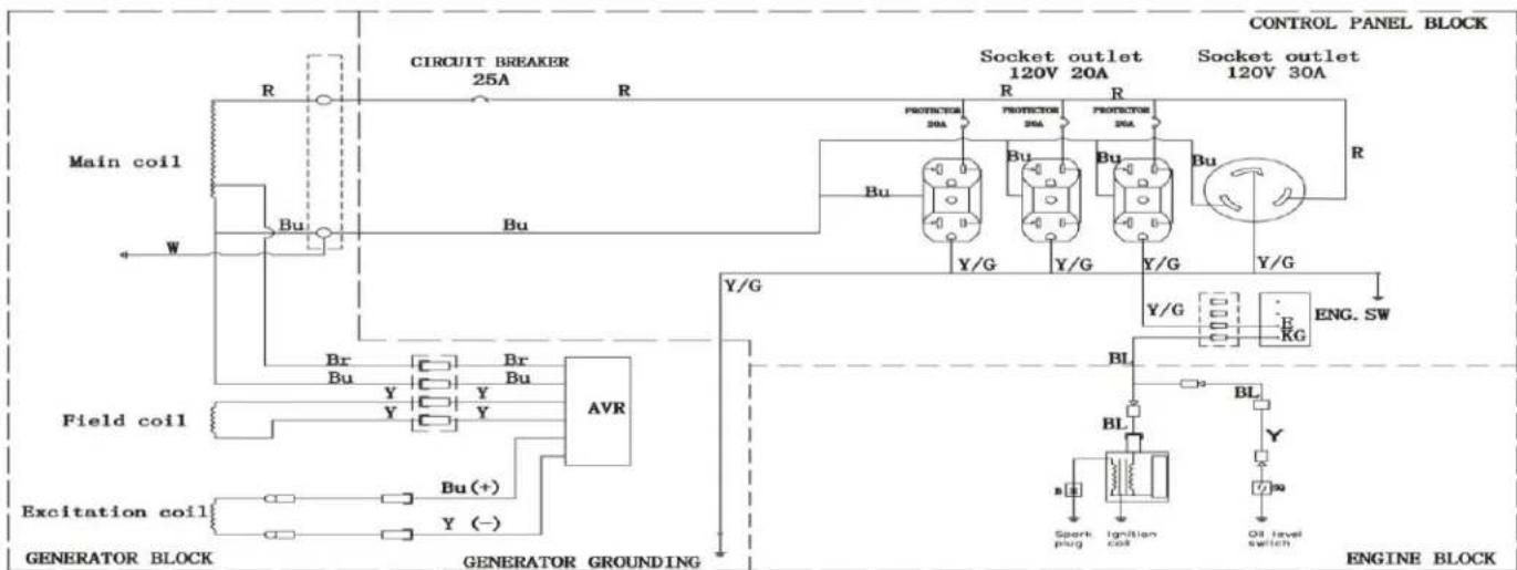
LIFAN POWER USA LIFAN LIFAN POWER USAWiring Diagram LF3500 & LF3500E
flowchart
graph TD
    A["Main coil"] -->|R| B["CIRCUIT BREAKER 25A"]
    A -->|W| C["Field coil"]
    A -->|Y/G| D["Generator Block"]
    A -->|Y/Y| E["Excitation coil"]
    B --> F["Controller Block"]
    C --> G["Generator Block"]
    D --> H["Engine Block"]
    F --> I["Socket outlet 120V 20A"]
    F --> J["Socket outlet 120V 30A"]
    G --> K["BL"]
    G --> L["BL"]
    G --> M["Oil level switch"]
    H --> N["SPark plug"]
    H --> O["Ignition coil"]
    H --> P["Engine SW"]
    style A fill:#f9f,stroke:#333
    style B fill:#ccf,stroke:#333
    style C fill:#cfc,stroke:#333
    style D fill:#fcc,stroke:#333
    style E fill:#ffc,stroke:#333
    style F fill:#cff,stroke:#333
    style G fill:#ffc,stroke:#333
    style H fill:#cfc,stroke:#333
    style I fill:#fcc,stroke:#333
    style J fill:#cfc,stroke:#333
    style K fill:#fcc,stroke:#333
    style L fill:#cfc,stroke:#333
    style M fill:#fcc,stroke:#333
| BNG. 0Y | KISS | |||||||
| BG | S | RAY | ST | BL | Black | R | Red | |
| GFP | ○ | ○ | Y | Yellow | V | White | ||
| GM | BU | Blue | Br | Brown | ||||
| START | G | Green | ||||||
text_image
CIRCUIT BREAKER 25A R R Main coil Bu W Bu AVR Field coil Excitation coil Generator BLOCK GENERATOR GROUNDING Socket outlet 120V 20A Socket outlet 120V 30A CONTROL PANEL BLOCK Y/G Y/G Y/G Y/G GENE R BLOCK protector 3A-4A BL BL BL Starting motor Spark plug Ignition coil Oil level sensor Eng. SW Br Bu Y Y Y Y Y Y BR Br L Coa Battery Starting motor B A2 Y Y Y Y Y Y Y Y Y Y Y Y| EO | E | BAT | ST | |
| OFF | ◎ | ◎ | ||
| ON | ||||
| START | ◎ | ◎ |
| BL | Black | K | Red |
| Y | Yellow | F | White |
| BU | Blue | Br | Brown |
| G | Green |

text_image
POWERED BY LIFAN CSA-CA-EPA CERTIFIED ENERGY STORM SERIES
text_image
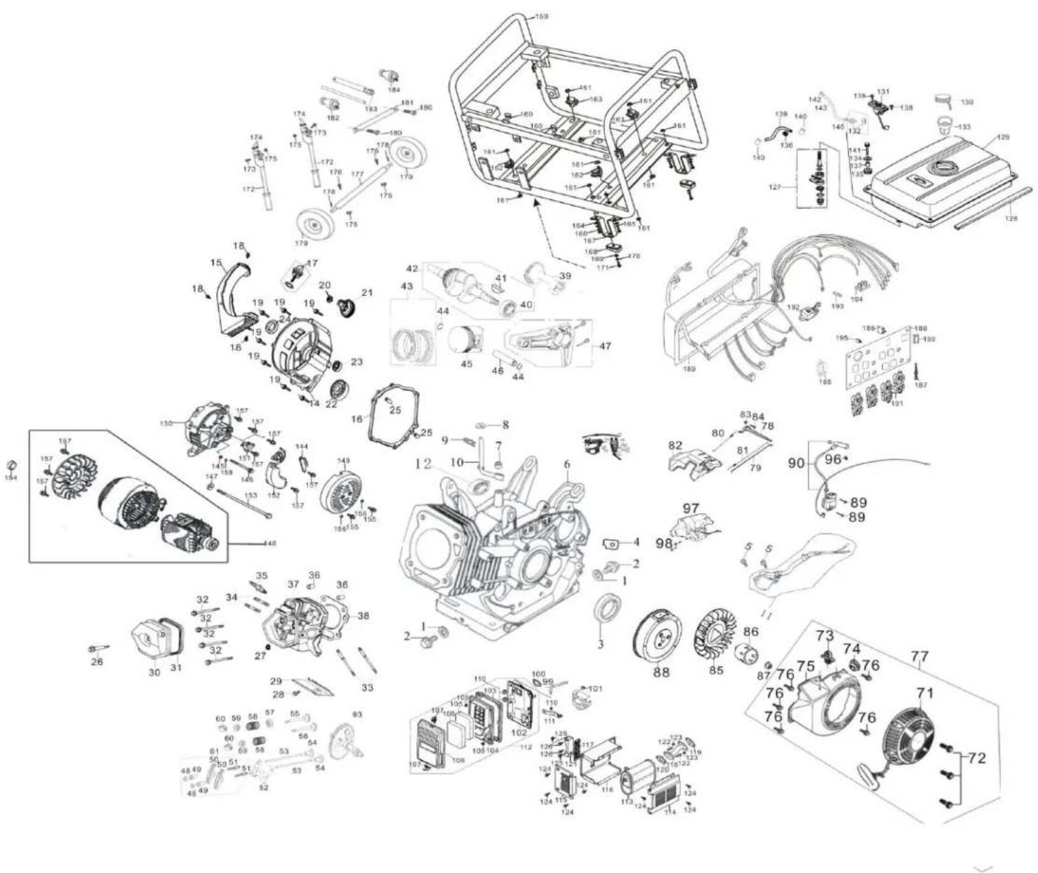
LIFAN POWER USA LIFAN LIFAN POWER USAEngine Exploded View & Parts
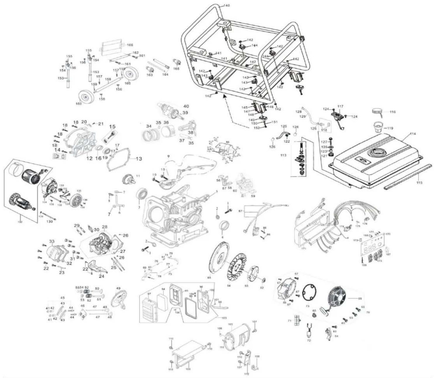
text_image
Exploded view diagram of a mechanical assembly with numbered components and exploded views
text_image
POWERED BY LIFAN CSA-CA-EPA CERTIFIED ENERGY STORM SERIES| Part | Code | Description | q'ty |
| 1 | 11115-A0710-0001 | Drain plug M10X15 | 2 |
| 2 | 11116-A0710-0001 | Washer | 2 |
| 3 | T910-0001 | Bearing 6205 | 1 |
| 4 | 11120-A0710-0002 | Oil seal, crankshaft | 1 |
| 5 | 11110-A0611-0001 | Crankcase | 1 |
| 6 | 26111-A0710-0001 | Regulating sway bar | 1 |
| 7 | 26113-A0710-0001 | Washer | 2 |
| 8 | 26112-A0710-0001 | Split pin | 1 |
| 9 | 27400-A0710-0002 | Oil sensor | 1 |
| 10 | T152-0004 | Bolt M6×14 | 2 |
| 11 | 25100-A0710-0004 | Driven gear assy, regulator | 1 |
| 12 | 11211-B9130-0001 | Crankcase cover | 1 |
| 13 | 11114-A0710-0001 | Gasket, crankcase | 1 |
| 14 | 15610-A0710-0001 | Oil plug with Seal | 1 |
| 15 | 15510-A0710-0001 | Dipstick with seal | 1 |
| 16 | 11120-A0710-0001 | Oil seal , crankshaft | 1 |
| 17 | 11113-A0710-0001 | Set pin Φ8×14 | 2 |
| 18 | T151-0001 | Bolt M8×32 | 6 |
| 19 | T910-0001 | Bearing 6205 | 1 |
| 20 | 11216-B9130-0001 | Dust plate | 1 |
| 21 | T151-0002 | Bolt M6×12 | 1 |
| 22 | T152-0019 | Bolt M6×12 | 6 |
| 23 | 19143-A0710-0001 | Air duck | 1 |
| 24 | 19121-A0721-0001 | Lead wind cover | 1 |
| 25 | 17218-A0710-0001 | Stud M6×96 | 2 |
| 26 | 12117-A0710-0001 | Set pin Φ10×16 | 2 |
| 27 | 12120-A0720-0001 | Gasket, cylinder head | 1 |
| 28 | 12100-A0721-0004 | Cylinder head Assy | 1 |
| 29 | 18214-A0710-0001 | Stud M8×34 | 2 |
| 30 | 27100-A0710-0001 | Spark plug F6TC | 1 |
| 31 | 12118-A0710-0001 | Bolt | 4 |
| 32 | 12212-A0721-0001 | Gasket, cylinder head cover | 1 |
| 33 | 12200-A0721-0001 | Cylinder head cover Assy | 1 |
| 34 | 13400-A0730-0001 | Piston ring assy | 1 |
| 35 | 13313-A0710-0001 | Piston pin circlip | 2 |
| 36 | 13311-A0720-0004 | Piston | 1 |
| 37 | 13312-A0710-0001 | Piston pin | 1 |
| 38 | 13120-A0710-0001 | Shank | 1 |
| 39 | 13112-A0710-0001 | Woodruff key | 1 |
| 40 | 13110-A0720-0002 | Crankshaft assy | 1 |
| 41 | 14314-A0710-0001 | Lock nut | 2 |
| 42 | 14312-A0710-0001 | Sleeve | 2 |
| 43 | 14311-A0710-0001 | Valve rocker | 2 |
| 44 | 14313-A0710-0001 | Adjusting bolt for valve gap | 2 |
| 45 | 14310-A0710-0001 | Valve rocker assy | 2 |
| 46 | 14220-A0710-0001 | Pusher guide | 1 |
| 47 | 14210-A0710-0001 | Pusher | 2 |
| 48 | 14315-A0720-0001 | Tappet | 2 |
| 49 | 14100-A0720-0005 | Camshaft Assy | 1 |
| 50 | 14412-A0710-0001 | Exhaust valve | 1 |
| 51 | 14411-A0710-0001 | Intake valve | 1 |
| 52 | 14414-A0710-0001 | Valve spring | 2 |
| 53 | 14413-A0710-0001 | Spring seat, intake valve | 1 |
| 54 | 14415-A0710-0001 | Spring seat, exhaust valve | 1 |
| 55 | 14416-A0710-0001 | Cap | 1 |
| 56 | 17219-A0710-0001 | Inlet gasket | 1 |
| 57 | 16120-A0710-0001 | Connecting block | 1 |
| 58 | 16113-A0710-0001 | Carburetor gasket | 1 |
| 59 | 17113-A0710-0001 | Air cleaner gasket | 1 |
| 60 | 16100-B9130-0001 | Carburetor Assy | 1 |
| 61 | 16244-A0720-0001 | Main nozzle | 1 |
| 62 | 16243-A0720-0001 | Main je | 1 |
| 63 | T152-0033 | Bolt M6×22 | 1 |
| 64 | 19300-A0710-0001 | Crankcase side plate assy | 1 |
| 65 | T210-0005 | Bolt M5×8 | 3 |
| 66 | 19211-A0714-0025 | Fan hood assy | 1 |
| 67 | T152-0019 | Bolt M6×12 | 4 |
| 68 | 19219-B9130-0001 | Fan hood latex stop up | 1 |
| 69 | 23200-A0710-0047 | Recoil starter | 1 |
| 70 | 23100-B9140-0030 | Recoil starter assy | 1 |
| 71 | 19313-A0710-0001 | Plastic clip | 1 |
| 72 | 27500-A0710-0001 | Diode | 1 |
| 73 | 23260-A0710-0001 | Recoil spacer combination | 1 |
| 74 | 26114-A0710-0001 | Regulating arm | 1 |
| 75 | 26115-A0710-0001 | Pulling rod | 1 |
| 76 | 26117-A0710-0001 | Back spring | 1 |
| 77 | 26118-A0710-0001 | Fine regulating spring | 1 |
| 78 | 26200-B9130-0001 | Regulating mount | 1 |
| 79 | T152-0019 | Nut M6 | 1 |
| 80 | T152-0019 | Bolt M6×12 | 2 |
| 81 | 26116-A0710-0001 | Lock bolt | 1 |
| 82 | 23317-A0710-0001 | Nut M14×1.5 | 1 |
| 83 | 23316-A0710-0002 | Starting flange | 1 |
| 84 | 19111-A0710-0001 | Flywheel fan | 1 |
| 85 | 23300-A0714-0001 | Flywheel | 1 |
| 86 | T152-0034 | Screw M6×25 | 2 |
| 87 | 27200-A0710-0001 | Ignition coil unit | 1 |
| 88 | 24100-A0714-0001 | Starting motor Assy | 1 |
| 89 | T411-0017 | Washer, M4 | 9 |
| 90 | T311-0002 | Nut, M6 | 2 |
| 91 | T151-0008 | Bolt, M8×35 | 2 |
| 92 | T411-0005 | Spring washer, 4 | 9 |
| 93 | T210-0006 | Screw, M4×14 | 7 |
| 94 | 17124-B9130-0002 | Filter element | 1 |
| 95 | 17125-B9130-0002 | Retainer, filter element | 1 |
| 96 | 17114-B9130-0002 | Air cleaner case | 1 |
| 97 | 17112-B9130-0002 | Air cleaner cover | 1 |
| 98 | 17233-B9130-0001 | Air cleaner stay | 1 |
| 99 | 17129-B9130-0001 | Gasket | 1 |
| 100 | 17117-A1310-0001 | Bolt | 4 |
| 101 | T152-0019 | Bolt M6×12 | 1 |
| 102 | 17140-B9130-0001 | Hinge | 2 |
| 103 | 17100-B9130-0006 | Air cleaner Assy | 1 |
| 104 | T314-0001 | Nut M6 | 2 |
| 105 | 18100-BC160-0005 | Muffler liner | 1 |
| 106 | 18130-B9130-0001 | Muffler guard | 1 |
| 107 | T151-0005 | Flange bolt M8×16 | 2 |
| 108 | 18150-B9130-0001 | Muffler stay . | 1 |
| 109 | T310-0001 | Nut M8 | 1 |
| 110 | T152-0019 | Flange bolt M6×12 | 6 |
| 111 | 18215-A0710-0001 | Exhaust pipe gasket | 2 |
| 112 | 18160-B9130-0001 | Supporting plate | 1 |
| 113 | 16640-B9130-0002 | Fuel cock assy | 1 |
| 114 | 16510-B9130-0073 | Fuel tank | 1 |
| 115 | 16912-B9130-0001 | Stripe, fuel tank | 1 |
| 116 | 16400-A0410-0002 | Fuel filler cap comp. | 1 |
| 117 | 16560-B9130-0001 | Oil indicator assy | 1 |
| 118 | 16557-A0710-0001 | 1 | |
| 119 | 16610-A0710-0003 | Fuel filler assy | 1 |
| 120 | 16546-B9130-0001 | Washer | 4 |
| 121 | 16911-B9130-0001 | Cushion | 4 |
| 122 | 16626-BC130-0001 | Vitta restrict | 1 |
| 123 | 16914-B9130-0001 | Bush | 4 |
| 124 | T211-0002 | Screw M5×12 | 2 |
| 125 | 16621-BC130-0004 | Outlet pipe (Φ8.5×Φ4.5×180) | 1 |
| 126 | 16622-A0710-0002 | Tube clip | 3 |
| 127 | T151-0003 | Bolt M6×22 (Flange) | 4 |
| 128 | 16622-A0710-0003 | Tube clip | 1 |
| 129 | 11513-B9130-0002 | Vent pipe | 1 |
| 130 | 31125-BC160-0001 | Bolt M8×215 | 1 |
| 131 | 31153-B9130-0001 | Bolt M5×12 | 3 |
| 132 | 31100-BB130-0025 | Stator & rotor Assy | 1 |
| 133 | 31130-B9130-0001 | Brush Assy | 1 |
| 131 | 31151-B9130-0001 | Generator stay | 1 |
| 135 | 31152-B9130-0002 | Generator end cover | 1 |
| 136 | T152-0027 | Bolt M5×50 | 2 |
| 137 | 31140-B9130-0001 | Voltage regulator | 1 |
| 138 | 31112-BF130-0001 | Flange bolt M6×164 | 4 |
| 139 | 31126-B9130-0001 | Plain washer | 1 |
| 140 | 32100-BB140-0116 | Frame | 1 |
| 141 | 32412-B9130-0001 | Rubber pad, frame | 2 |
| 142 | T311-0001 | Nut M8 | 10 |
| 143 | 32420-B9130-0001 | Cushion, frame A | 2 |
| 144 | 32450-B9130-0001 | Cushion, frame B | 2 |
| 145 | T411-0001 | Plain washer | 4 |
| 146 | T441-0001 | Plain washer | 4 |
| 147 | T151-0006 | Flange bolt M8×25 | 4 |
| 148 | 32231-BB140-0006 | Bracket | 2 |
| 149 | 31523-BF140-0001 | Bracket cushion | 2 |
| 150 | T411-0002 | Plain washerΦ6 | 2 |
| 151 | T441-0002 | Plain washerΦ6 | 2 |
| 152 | T151-0005 | Flange bolt M8×16 | 2 |
| 153 | 32417-BC130-0001 | Armrest | 2 |
| 154 | 32139-BB140-0001 | Flange bolt | 2 |
| 155 | 31161-B9130-0001 | Handle gasket | 4 |
| 156 | T311-0001 | Nut M8 | 4 |
| 157 | T151-0006 | Flange bolt M8×25 | 8 |
| 158 | 31311-B9130-0002 | Wheel axel, | 1 |
| 159 | 31352-B9130-0002 | Split pin | 2 |
| 160 | 45420-B9130-0019 | Wheel kit | 2 |
| 161 | T152-0019 | Flange bolt M6×12 | 2 |
| 162 | 32433-B9140-0002 | Battery box cover | 1 |
| 163 | 31224-B9130-0006 | Plug (30A) | 2 |
| 164 | 92230-B9130-0001 | Sparking plug wrench(short) | 1 |
| 165 | 31247-B9130-0001 | Plug | 1 |
| 166 | 32416-BB140-0001 | Battery box | 1 |
| 167 | 31223-B9130-0010 | 3-prong twisted | 1 |
| 168 | 31221-B9130-0054 | Circuit protector, | 1 |
| 169 | 31222-B9130-0001 | Earth terminal set | 1 |
| 170 | 31211-B9130-0131 | Control panel front cover | 1 |
| 171 | 31200-BG140-0141 | Control panel back cover | 1 |
| 172 | 31225-B9140-0001 | gnition switch | 1 |
| 173 | 31223-B9130-0008 | 3-prong twisted | 4 |
| 174 | 35368-G1211-0001 | Current transformer | 1 |
| 175 | 31276-B9130-0001 | Fuse case | 3 |
| 176 | 31280-BC130-0001 | Bridge ballast | 1 |
| 177 | 31218-B9130-0002 | protector | 5 |

text_image
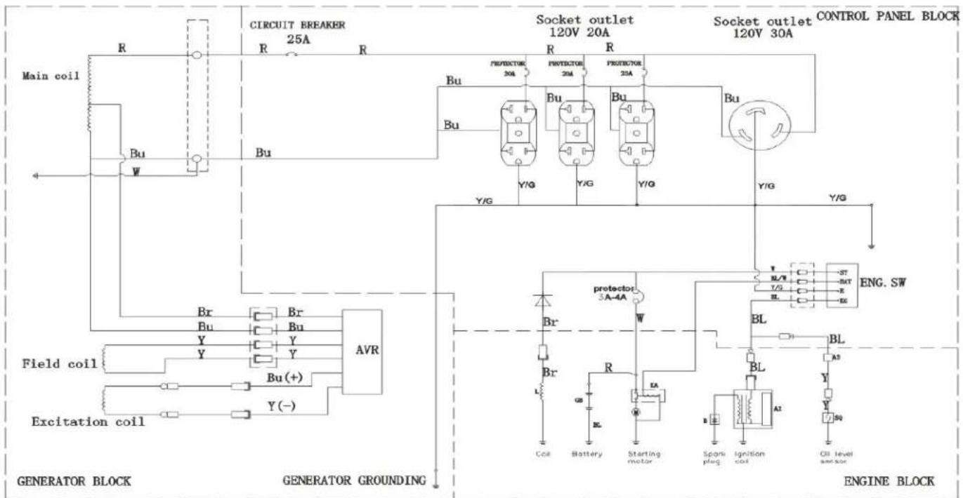
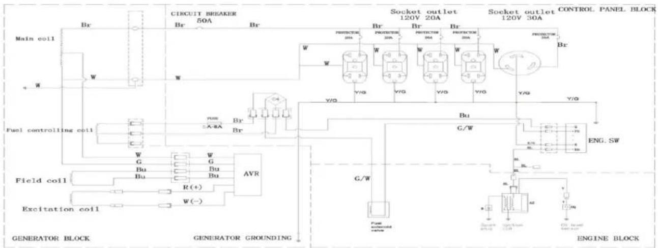
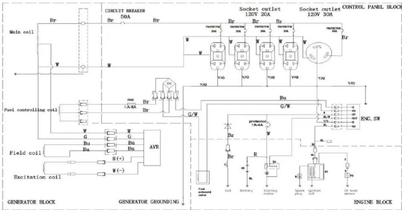
LIFAN POWER USA LIFAN LIFAN POWER USAWiring Diagram LF6500 & LF6500E
text_image
CIRCUIT BREAKER 50A Main coil W Fuel controlling coil Field coil Excitation coil GENERATOR BLOCK GENERATOR GROUNDING Socket outlet 120V 20A Socket outlet 120V 30A CONTROL PANEL BLOCK PROTECTION PROTECTION PROTECTION PROTECTION PROTECTION PROTECTION PROTECTION PROTECTION PROTECTION PROTECTION PROTECTION PROTECTION PROTECTION PROTECTION PROTECTION PROTECTION PROTECTION PROTECTION PROTECTION PROTECTION PROTECTION PROTECTION PROTECTION PROTECTION PROTECTION PROTECTION PROTECTION PROTECTION PROTECTION PROTECTION PROTECTION PROTECTION PROTECTION PROTECTION| A1 | E | G | F5 | |
| DVP | ||||
| ON |
| WIND | |||
| SL. | Willach | N | Sweet |
| V | Willaue | M | White |
| BRJ | Willow | By | Brownes |
| G | Brownes | ||
text_image
CIRCUIT BREAKER 50A Main coil Fuel controlling coil Field coil Excitation coil Generator Block Generator GROUNDING Socket outlet 120V 20A Socket outlet 120V 30A CONTROL PANEL BLOCK PROTECTION 20A PROTECTION 20A PROTECTION 20A PROTECTION 20A PROTECTION 20A PROTECTION 20A PROTECTION 20A PROTECTION 20A PROTECTION 20A PROTECTION 20A PROTECTION 20A PROTECTION 20A PROTECTION 20A PROTECTION 20A PROTECTION 20A PANE 5A-EA Br Br G/W Bu G/W AVR Fuel extensoid valve Coil Battery Starting motor Spark plug Ignition coil DR level sensor GEN. SW ENGINE BLOCK- SW
| E2 | E | MT | DT | ∅ | PS | |
| GFP | ∅ | ∅ | ∅ | ∅ | ||
| BR | ||||||
| START | ∅ | ∅ |
WIRE
| BL | Black | S | Red |
| Y | Yellow | W | White |
| SU | Blue | Br | Brown |
| G | Green |

text_image
POWERED BY LIFAN CSA-CA-EPA CERTIFIED ENERGY STORM SERIES
text_image
LIFAN POWER USA LIFAN LIFAN POWER USAEngine Exploded View & Parts
text_image
Exploded view diagram of a mechanical assembly with numbered components and exploded views
text_image
POWERED BY LIFAN CSA-CA-EPA CERTIFIED ENERGY STORM SERIES| Part | Code | Description | q'ty |
| 1 | 11116-A0810-0001 | Washer | 2 |
| 2 | 11115-A0810-0001 | Drain plug | 2 |
| 3 | 11120-A1010-0001 | Oil seal, crankshaft Assy (一) | 1 |
| 4 | 11117-A0810-0001 | Seal | 1 |
| 5 | T152-0004 | Bolt M6×14 | 2 |
| 6 | 11110-A1110-0005 | Crankcase | 1 |
| 7 | 11130-A1010-0001 | Oil seal, regulating sway bar | 1 |
| 8 | 26113-A0810-0001 | Washer | 2 |
| 9 | 26112-A0810-0001 | Split pin | 1 |
| 10 | 26111-A1010-0001 | Regulating sway bar | 1 |
| 11 | 27400-A0810-0002 | Oil sensor Assy | 1 |
| 12 | T910-0005 | Bearing 6202 | 1 |
| 14 | 11211-BF130-0001 | Crankcase cover | 1 |
| 15 | 11220-BF130-0001 | Guard, crankcase cover Assy | 1 |
| 16 | 11114-A1010-0001 | Gasket, crankcase | 1 |
| 17 | 15510-BC130-0001 | Dipstick | 1 |
| 18 | 31153-BC130-0002 | Bolt M5×14 | 3 |
| 19 | T151-0013 | Bolt M8×40 | 7 |
| 20 | 25118-A0810-0001 | Washer, driven gear | 1 |
| 21 | 25100-A1210-0001 | Driven gear set, regulator assy | 1 |
| 22 | T910-0003 | Bearing 6207 | 1 |
| 23 | T910-0005 | Bearing 6202 | 1 |
| 24 | 11120-A1010-0001 | Oil seal , crankshaft assy (一) | 1 |
| 25 | 11113-A0810-0001 | Set pinΦ8×12 | 2 |
| 26 | 12220-A0810-0001 | Bolt Assy | 1 |
| 27 | 14420-A0810-0001 | Seal Assy | 1 |
| 28 | T152-0019 | Bolt:M6×12 | 1 |
| 29 | 19121-A1010-0001 | Lead wind cover (一) | 1 |
| 30 | 12200-A0810-0001 | Cylinder head cover Assy | 1 |
| 31 | 12212-A0810-0001 | Gasket, cylinder head cover | 1 |
| 32 | 12118-A0810-0001 | Bolt | 4 |
| 33 | 17218-BF130-0001 | Stud M6×M8×106 | 2 |
| 34 | 18214-A0710-0001 | Stud M8×34 | 2 |
| 35 | 27100-A0710-0001 | Spark plug Assy | 1 |
| 36 | 12117-A0810-0001 | Set pin | 2 |
| 37 | 12100-A1110-0001 | Cylinder head Assy | 1 |
| 38 | 12120-A1110-0004 | Gasket, cylinder head Assy | 1 |
| 39 | 13116-A1210-0001 | Balancing shaft | 1 |
| 40 | T910-0003 | Bearing 6207 | 1 |
| 41 | 13112-A0710-0001 | Wood ruff key | 1 |
| 42 | 13110-A1010-0002 | Crankshaft assy | 1 |
| 43 | 13400-A1110-0005 | Piston ring set | 1 |
| 44 | 13313-A1010-0001 | Piston pin circlip | 2 |
| 45 | 13311-A1110-0005 | Piston | 1 |
| 46 | 13312-A1010-0001 | Piston pin | 1 |
| 47 | 13120-A1010-0001 | Connecting rod assy | 1 |
| 48 | 14314-A0710-0001 | Lock nut | 2 |
| 49 | 14312-A0710-0001 | Sleeve | 2 |
| 50 | 14311-A0810-0001 | Valve rocker | 2 |
| 51 | 14313-A0710-0001 | Adjusting bolt for valve gap | 2 |
| 52 | 14220-A0810-0002 | Pusher guide | 1 |
| 53 | 14210-A1010-0001 | Pusher | 2 |
| 54 | 14315-A0810-0001 | Tappet | 2 |
| 55 | 14412-A1110-0001 | Exhaust valve | 1 |
| 56 | 14411-A1110-0001 | Intake valve | 1 |
| 57 | 14417-A0810-0001 | Spring retainer, exhaust valve | 1 |
| 58 | 14414-A0810-0001 | Valve spring | 2 |
| 59 | 14413-A1010-0001 | Spring seat, exhaust valve | 2 |
| 60 | 14418-A1010-0001 | Valve lock clamp | 4 |
| 61 | 14310-A0810-0001 | Valve rocker assy | 1 |
| 62 | 17219-A1010-0001 | Inlet gasket | 1 |
| 63 | 16120-BG130-0001 | Float needle | 1 |
| 64 | 16113-A1110-0001 | Carburetor gasket | 1 |
| 65 | 16100-BG130-0004 | Carburetor Assy | 1 |
| 66 | 16800-BC130-0001 | Manual choke Assy | 1 |
| 67 | 16244-BJ130-0001 | Main nozzle | 1 |
| 68 | 16243-A1210-0001 | Main jet | 1 |
| 69 | 17113-A0810-0003 | Gasket, air cleaner | 1 |
| 70 | 16840-BC130-0001 | Check valve Assy | 1 |
| 71 | 23200-A1010-0014 | Recoil starter assy | 1 |
| 72 | T152-0036 | Bolt M6×8 | 3 |
| 73 | 16845-BC130-0001 | Friction spring | 2 |
| 74 | 19219-B9130-0001 | Fan hood latex stop up | 1 |
| 75 | 19211-BF130-0020 | Fan hood assy | 1 |
| 76 | T152-0019 | Bolt M6×12 | 5 |
| 77 | 23100-BF130-0062 | Recoil starter assy | 1 |
| 78 | 26114-G1110-0001 | Regulating arm | 1 |
| 79 | 26115-A1010-0001 | Pulling rod | 1 |
| 80 | 26117-A1010-0001 | Back spring | 1 |
| 81 | 26118-A1010-0001 | Fine regulating spring | 1 |
| 82 | 26200-BF130-0001 | Regulating frame assy | 1 |
| 83 | T311-0002 | Nut M6 | 1 |
| 84 | 26116-A0710-0001 | Lock bolt | 1 |
| 85 | 19111-A1210-0001 | Flywheel fan | 1 |
| 86 | 23316-A1010-0002 | Starting flange | 1 |
| 87 | 23317-A0810-0002 | Nut M16×1.5 | 1 |
| 88 | 23300-A1114-0001 | Flywheel | 1 |
| 89 | T152-0034 | Bolt M6×25 | 2 |
| 90 | 27200-A1110-0001 | Ignition coil uni | 1 |
| 93 | 14100-A1110-0004 | Camshaft assy | 1 |
| 96 | 19316-A0810-0002 | Cable tie | 1 |
| 97 | 24100-A1014-0001 | Starting motor Assy | 1 |
| 98 | T151-0013 | Bolt, M8×40 | 2 |
| 99 | 19143-BC130-0001 | Waste pipe | 1 |
| 100 | 17223-BC130-0001 | Boot, vent pipe | 1 |
| 101 | 17113-A0810-0003 | Gasket, air cleaner | 1 |
| 102 | 17114-BC130-0002 | Air cleaner base | 1 |
| 103 | 17129-BC130-0001 | Gasket | 1 |
| 104 | 17125-BC130-0001 | Retainer, filter element | 1 |
| 105 | 17126-A2110-0001 | Filter(二) | 1 |
| 106 | 17124-B9130-0002 | Filter(一) | 1 |
| 107 | 17140-BC130-0001 | Hinge | 1 |
| 108 | 17112-BC130-0001 | Air cleaner cover | 1 |
| 109 | T314-0006 | Nut M5 | 6 |
| 110 | T314-0001 | Nut M6 | 3 |
| 111 | 17233-BC130-0001 | Air cleaner stay | 1 |
| 112 | 17100-BC130-0004 | Air cleaner Assy | 1 |
| 113 | 18100-BJ130-0001 | Muffler assy | 1 |
| 114 | 18130-BC130-0001 | Muffler Outer hood assy | 1 |
| 115 | 18230-BC130-0001 | Muffler hood (一) | 1 |
| 116 | 18240-BJ130-0001 | Muffler hood (二) | 1 |
| 117 | 18162-BC130-0001 | Muffler stay airproof | 1 |
| 118 | 18117-BF130-0001 | Exhaust pipe | 1 |
| 119 | 18217-BC130-0001 | Gasket, exhaust pipe | 1 |
| 120 | 18215-BC130-0001 | Gasket, outlet | 1 |
| 121 | 18161-BC130-0001 | Muffler stay assy | 1 |
| 122 | T151-0016 | Flange bolt M8×25 | 2 |
| 123 | T310-0001 | Nut M8 | 2 |
| 124 | T152-0019 | Flange bolt M6×12 | 7 |
| 125 | T151-0014 | Flange bolt M8×12 | 2 |
| 126 | T151-0005 | 螺栓 M8×16 | 2 |
| 127 | 16640-B9130-0002 | Fuel cock assy | 1 |
| 128 | 16510-BC130-0081 | Fuel tank | 1 |
| 129 | 16912-BC130-0001 | Stripe, fuel tank | 1 |
| 130 | 16400-A0410-0002 | Fuel filler cap comp. | 1 |
| 131 | 16560-B9130-0001 | Oil indicator assy | 1 |
| 132 | 16557-A0710-0001 | Air outlet joint | 1 |
| 133 | 16610-A0710-0003 | Fuel filler assy | 1 |
| 134 | 16546-B9130-0001 | Washer | 4 |
| 135 | 16911-B9130-0001 | Cushion | 4 |
| 136 | 16626-BC130-0001 | Vitta restrict | 1 |
| 137 | 16914-B9130-0001 | Bush | 4 |
| 138 | T211-0002 | Screw M5×12 | 2 |
| 139 | 16621-BC130-0004 | Outlet pipe (Φ8.5×Φ4.5×180) | 1 |
| 140 | 16622-A0710-0002 | Tube clip | 3 |
| 141 | T151-0003 | Bolt M6×22 (Flange) | 4 |
| 142 | 16622-A0710-0003 | Tube clip | 1 |
| 143 | 11513-A0710-0002 | Vent pipe | 1 |
| 144 | 31154-BC130-0002 | Connecting plate | 1 |
| 145 | T411-0002 | Washer 6mm | 4 |
| 146 | 31112-BG130-0001 | Bolt M6×179 | 4 |
| 147 | 31126-BC130-0001 | Plain washer | 1 |
| 148 | 31100-BG130-0037 | Stator & rotor Assy | 1 |
| 149 | 31152-BC130-0003 | Generator end cover | 1 |
| 150 | 31151-BC130-0001 | Generator stay | 1 |
| 151 | 31130-BC130-0001 | Brush Assy | 1 |
| 152 | 31140-BC130-0001 | Voltage regulator assy | 1 |
| 153 | 31125-BG130-0001 | Bolt M10×285 | 1 |
| 154 | 11312-BC130-0001 | Plug, sump | 1 |
| 155 | 31153-A0410-0001 | Bolt M5×10 | 2 |
| 156 | 31511-A1713-0001 | Red washer 5mm | 2 |
| 157 | 31153-BC130-0002 | Screw M5×14 | 7 |
| 158 | T441-0002 | Spring washer 6mm | 4 |
| 159 | 32100-BG140-0133 | Frame | 1 |
| 160 | 32412-B9130-0001 | Rubber pad, frame | 2 |
| 161 | T311-0001 | Nut M8 | 10 |
| 162 | 32420-BC130-0001 | Cushion, frame A | 2 |
| 163 | 32450-BC130-0001 | Cushion, frame B | 2 |
| 164 | T411-0001 | Plain washer | 4 |
| 165 | T441-0001 | Plain washer | 4 |
| 166 | T151-0006 | Flange bolt M8×25 | 4 |
| 167 | 32231-BB140-0003 | Bracket | 2 |
| 168 | 31523-BF140-0001 | Bracket cushion | 2 |
| 169 | T411-0002 | Plain washerΦ6 | 2 |
| 170 | T441-0002 | Plain washerΦ6 | 2 |
| 171 | T151-0005 | Flange bolt M8×16 | 2 |
| 172 | 32417-BC130-0001 | Armrest | 2 |
| 173 | 32139-BB140-0001 | Flange bolt | 2 |
| 174 | 31161-B9130-0001 | Handle gasket | 4 |
| 175 | T311-0001 | Nut M8 | 4 |
| 176 | T151-0006 | Flange bolt M8×25 | 8 |
| 177 | 31311-BC130-0002 | Wheel axel, | 1 |
| 178 | 31352-B9130-0002 | Split pin | 2 |
| 179 | 45420-B9130-0019 | Wheel kit | 2 |
| 180 | T152-0019 | Flange bolt M6×12 | 2 |
| 181 | 32433-BG140-0001 | Battery box cover | 1 |
| 182 | 31224-B9130-0006 | Plug (30A) | 2 |
| 183 | 92230-B9130-0001 | Sparking plug wrench(short) | 1 |
| 184 | 31224-B9130-0032 | Plug | 1 |
| 185 | 31223-B9130-0010 | 3-prong twisted | 1 |
| 186 | 31221-B9130-0054 | Circuit protector, | 1 |

text_image
LIFAN POWER USA LIFAN LIFAN POWER USA| 187 | 31222-B9130-0001 | Earth terminal set | 1 |
| 188 | 31211-B9130-0014 | Control panel front cover | 1 |
| 189 | 31200-BG140-0141 | Control panel back cover | 1 |
| 190 | 31225-B9140-0001 | gnition switch | 1 |
| 191 | 31223-B9130-0008 | 3-prong twisted | 4 |
| 192 | 35368-G1211-0001 | Current transformer | 1 |
| 193 | 31276-B9130-0001 | Fuse case | 3 |
| 194 | 31280-BC130-0001 | Bridge ballast | 1 |
| 195 | 31218-B9130-0002 | protector | 5 |

text_image
LIFAN POWER USA LIFAN LIFAN POWER USAWiring Diagram LF8000E
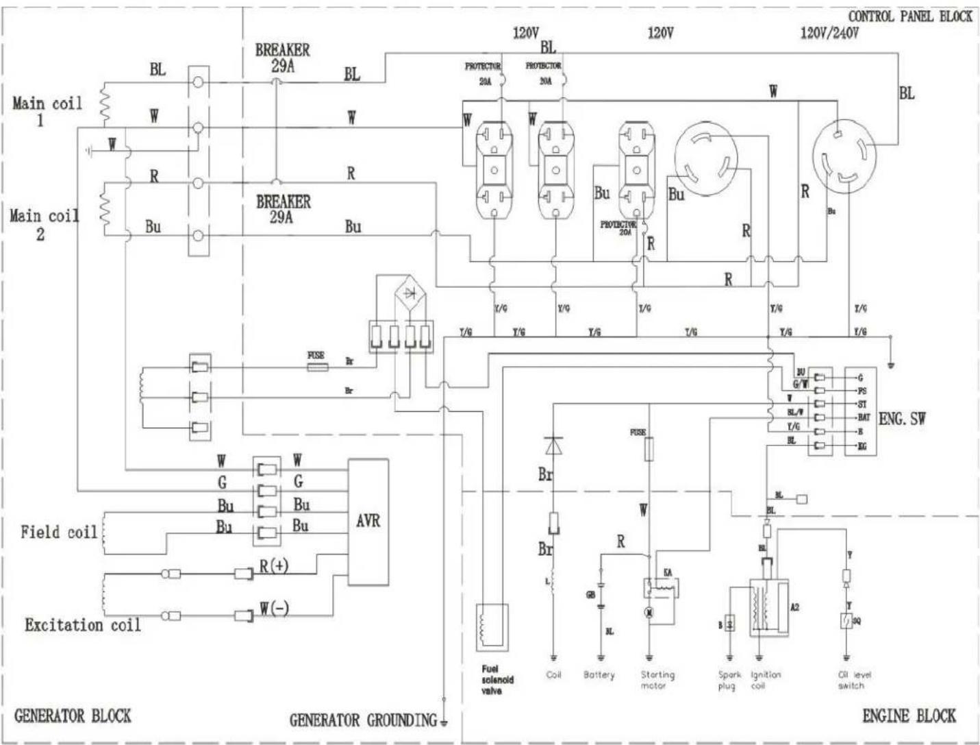
text_image
CONTROL PANEL BLOCK 120V 120V 120V/240V BREAKER 29A BL PROTECTOR 20A PROTECTOR 20A W BL PROTECTOR 20A W R BU PROTECTOR 20A BU R BU R BL MAIN COIL 1 W R Bu BRAKER 29A BRU FUSE Br Y/G Y/G Y/G Y/G Y/G Y/G Y/G FUSE BR Field coil G W G AVR Bu Bu Bu R(+) Excitation coil W(-) Fuel solenoid valve Coil Battery Starting motor Spark plug Ignition coil Oil level switch GENRATOR BLOCK GENERATOR GROUNDING ENGINE BLOCKENGL ST
| KG | B | BAT | ST | G | FS | |
| OFF | ||||||
| ON | ||||||
| START |
TRE
| BL | Black | K | Red |
| Y | Yellow | V | White |
| BU | Blue | Br | Brown |
| G | Green |

text_image
POWERED BY LIFAN CSA-CA-EPA CERTIFIED ENERGY STORM SERIES
text_image
LIFAN POWER USA LIFAN LIFAN POWER USAEngine Exploded View & Parts
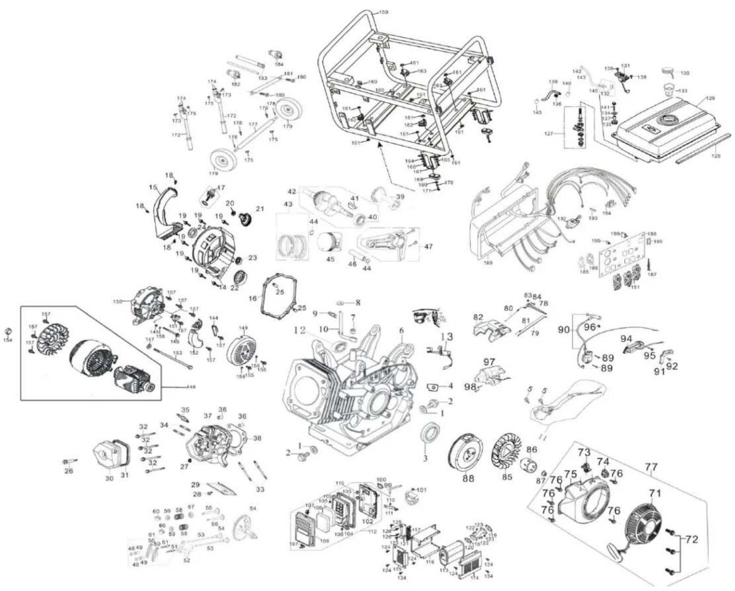
text_image
Exploded view diagram of a mechanical assembly with numbered parts and exploded views
text_image
POWERED BY LIFAN CSA-CA-EPA CERTIFIED ENERGY STORM SERIES| Part | Code | Description | q' ly |
| 1 | 11116-A0810-0001 | Washer | 2 |
| 2 | 11115-A0810-0001 | Drain plug | 2 |
| 3 | 11120-A1010-0001 | Oil seal, crankshaft Assy (一) | 1 |
| 4 | 11117-A0810-0001 | Seal | 1 |
| 5 | T152-0004 | Bolt M6×14 | 2 |
| 6 | 11110-A1214-0005 | Crankcase | 1 |
| 7 | 11130-A1010-0001 | Oil seal, regulating sway bar | 1 |
| 8 | 26113-A0810-0001 | Washer | 2 |
| 9 | 26112-A0810-0001 | Split pin | 1 |
| 10 | 26111-A1010-0001 | Regulating sway bar | 1 |
| 11 | 27400-A0810-0002 | Oil sensor Assy | 1 |
| 12 | T910-0005 | Bearing 6202 | 1 |
| 13 | 26500-G1110-0001 | Electromagnet | 1 |
| 14 | 11211-BF130-0001 | Crankcase cover | 1 |
| 15 | 11220-BF130-0001 | Guard, crankcase cover Assy | 1 |
| 16 | 11114-A1010-0001 | Gasket, crankcase | 1 |
| 17 | 15510-BC130-0001 | Dipstick | 1 |
| 18 | 31153-BC130-0002 | Bolt M5×14 | 3 |
| 19 | T151-0013 | Bolt M8×40 | 7 |
| 20 | 25118-A0810-0001 | Washer, driven gear | 1 |
| 21 | 25100-A1210-0001 | Driven gear set, regulator assy | 1 |
| 22 | T910-0003 | Bearing 6207 | 1 |
| 23 | T910-0005 | Bearing 6202 | 1 |
| 24 | 11120-A1010-0001 | Oil seal , crankshaft assy (一) | 1 |
| 25 | 11113-A0810-0001 | Set pinΦ8×12 | 2 |
| 26 | 12220-A0810-0001 | Bolt Assy | 1 |
| 27 | 14420-A0810-0001 | Seal Assy | 1 |
| 28 | T152-0019 | Bolt:M6×12 | 1 |
| 29 | 19121-A1010-0001 | Lead wind cover (一) | 1 |
| 30 | 12200-A0810-0001 | Cylinder head cover Assy | 1 |
| 31 | 12212-A0810-0001 | Gasket, cylinder head cover | 1 |
| 32 | 12118-A0810-0001 | Bolt | 4 |
| 33 | 17218-BF130-0001 | Stud M6×M8×106 | 2 |
| 34 | 18214-A0710-0001 | Stud M8×34 | 2 |
| 35 | 27100-A0710-0001 | Spark plug Assy | 1 |
| 36 | 12117-A0810-0001 | Set pin | 2 |
| 37 | 12100-A1210-0002 | Cylinder head Assy | 1 |
| 38 | 12120-A1210-0001 | Gasket, cylinder head Assy | 1 |
| 39 | 13116-A1210-0001 | Balancing shaft | 1 |
| 40 | T910-0003 | Bearing 6207 | 1 |
| 41 | 13112-A0710-0001 | Wood ruff key | 1 |
| 42 | 13110-A1210-0002 | Crankshaft assy | 1 |
| 43 | 13400-A1210-0003 | Piston ring set | 1 |
| 41 | 13313-A1010-0001 | Piston pin circlip | 2 |
| 45 | 13311-A1210-0004 | Piston | 1 |
| 46 | 13312-A1010-0001 | Piston pin | 1 |
| 47 | 13120-A1210-0001 | Connecting rod assy | 1 |
| 48 | 14314-A0710-0001 | Lock nut | 2 |
| 49 | 14312-A0710-0001 | Sleeve | 2 |
| 50 | 14311-A0810-0001 | Valve rocker | 2 |
| 51 | 14313-A0710-0001 | Adjusting bolt for valve gap | 2 |
| 52 | 14220-A0810-0002 | Pusher guide | 1 |
| 53 | 14210-A1010-0001 | Pusher | 2 |
| 54 | 14315-A0810-0001 | Tappet | 2 |
| 55 | 14412-A1210-0001 | Exhaust valve | 1 |
| 56 | 14411-A1010-0003 | Intake valve | 1 |
| 57 | 14417-A0810-0001 | Spring retainer, exhaust valve | 1 |
| 58 | 14414-A0810-0001 | Valve spring | 2 |
| 59 | 14413-A1010-0001 | Spring seat, exhaust valve | 2 |
| 60 | 14418-A1010-0001 | Valve lock clamp | 4 |
| 61 | 14310-A0810-0001 | Valve rocker assy | 1 |
| 62 | 17219-A1010-0001 | Inlet gasket | 1 |
| 63 | 16120-BG130-0001 | Float needle | 1 |
| 64 | 16113-A1110-0001 | Carburetor gasket | 1 |
| 65 | 16100-BJ130-0001 | Carburetor Assy | 1 |
| 66 | 16800-BC130-0001 | Manual choke Assy | 1 |
| 67 | 16244-BJ130-0001 | Main nozzle | 1 |
| 68 | 16243-A1210-0001 | Main jet | 1 |
| 69 | 17113-A0810-0003 | Gasket, air cleaner | 1 |
| 70 | 16840-BC130-0001 | Check valve Assy | 1 |
| 71 | 23200-A1010-0014 | Recoil starter assy | 1 |
| 72 | T152-0036 | Bolt M6×8 | 3 |
| 73 | 16845-BC130-0001 | Friction spring | 2 |
| 74 | 19219-B9130-0001 | Fan hood latex stop up | 1 |
| 75 | 19211-BF130-0020 | Fan hood assy | 1 |
| 76 | T152-0019 | Bolt M6×12 | 5 |
| 77 | 23100-BF130-0062 | Recoil starter assy | 1 |
| 78 | 26114-G1110-0001 | Regulating arm | 1 |
| 79 | 26115-A1010-0001 | Pulling rod | 1 |
| 80 | 26117-A1010-0001 | Back spring | 1 |
| 81 | 26118-A1010-0001 | Fine regulating spring | 1 |
| 82 | 26200-BF130-0001 | Regulating frame assy | 1 |
| 83 | T311-0002 | Nut M6 | 1 |
| 84 | 26116-A0710-0001 | Lock bolt | 1 |
| 85 | 19111-A1210-0001 | Flywheel fan | 1 |
| 86 | 23316-A1010-0002 | Starting flange | 1 |
| 87 | 23317-A0810-0002 | Nut M16×1.5 | 1 |
| 88 | 23300-A1114-0001 | Flywheel | 1 |
| 89 | T152-0034 | Bolt M6×25 | 2 |
| 90 | 27200-A1110-0001 | Ignition coil uni | 1 |
| 91 | 24145-A1014-0001 | Clamper, cord | 1 |
| 92 | T152-0019 | Bolt M6×12 | 1 |
| 93 | 14100-A1210-0002 | Camshaft assy | 1 |
| 94 | 24130-A0714-0001 | Charge coil | 1 |
| 95 | T152-0011 | Bolt M6×28 | 2 |
| 96 | 19316-A0810-0002 | Cable tie | 1 |
| 97 | 24100-A1014-0001 | Starting motor Assy | 1 |
| 98 | T151-0013 | Bolt, M8×40 | 2 |
| 99 | 19143-BC130-0001 | Waste pipe | 1 |
| 100 | 17223-BC130-0001 | Boot, vent pipe | 1 |
| 101 | 17113-A0810-0003 | Gasket, air cleaner | 1 |
| 102 | 17114-BC130-0002 | Air cleaner base | 1 |
| 103 | 17129-BC130-0001 | Gasket | 1 |
| 104 | 17125-BC130-0001 | Retainer, filter element | 1 |
| 105 | 17126-A2110-0001 | Filter(一) | 1 |
| 106 | 17124-B9130-0002 | Filter(一) | 1 |
| 107 | 17140-BC130-0001 | Hinge | 1 |
| 108 | 17112-BC130-0001 | Air cleaner cover | 1 |
| 109 | T314-0006 | Nut M5 | 6 |
| 110 | T314-0001 | Nut M6 | 3 |
| 111 | 17233-BC130-0001 | Air cleaner stay | 1 |
| 112 | 17100-BC130-0004 | Air cleaner Assy | 1 |
| 113 | 18100-BJ1Y1-0005 | Muffler assy | 1 |
| 114 | 18130-BC130-0001 | Muffler Outer hood assy | 1 |
| 115 | 18230-BC130-0001 | Muffler hood (一) | 1 |
| 116 | 18240-BJ1Y1-0001 | Muffler hood (二) | 1 |
| 117 | 18162-BC130-0001 | Muffler stay airproof | 1 |
| 118 | 18117-BF130-0001 | Exhaust pipe | 1 |
| 119 | 18217-BC130-0001 | Gasket, exhaust pipe | 1 |
| 120 | 18215-BC130-0001 | Gasket, outlet | 1 |
| 121 | 18161-BC130-0001 | Muffler stay assy | 1 |
| 122 | T151-0016 | Flange bolt M8×25 | 2 |
| 123 | T310-0001 | Nut M8 | 2 |
| 124 | T152-0019 | Flange bolt M6×12 | 7 |
| 125 | T151-0014 | Flange bolt M8×12 | 2 |
| 126 | T151-0005 | 螺栓 M8×16 | 2 |
| 127 | 16640-B9130-0002 | Fuel cock assy | 1 |
| 128 | 16510-BC130-0081 | Fuel tank | 1 |
| 129 | 16912-BC130-0001 | Stripe, fuel tank | 1 |
| 130 | 16400-A0410-0002 | Fuel filler cap comp. | 1 |
| 131 | 16560-B9130-0001 | Oil indicator assy | 1 |
| 132 | 16557-A0710-0001 | Air outlet joint | 1 |
| 133 | 16610-A0710-0003 | Fuel filler assy | 1 |
| 134 | 16546-B9130-0001 | Washer | 4 |
| 135 | 16911-B9130-0001 | Cushion | 4 |
| 136 | 16626-BC130-0001 | Vitta restrict | 1 |
| 137 | 16914-B9130-0001 | Bush | 4 |
| 138 | T211-0002 | Screw M5×12 | 2 |
| 139 | 16621-BC130-0004 | Outlet pipe (Φ8.5×Φ4.5×180) | 1 |
| 140 | 16622-A0710-0002 | Tube clip | 3 |
| 141 | T151-0003 | Bolt M6×22 (Flange) | 4 |
| 142 | 16622-A0710-0003 | Tube clip | 1 |
| 143 | 11513-A0710-0002 | Vent pipe | 1 |
| 144 | 31154-BC130-0002 | Connecting plate | 1 |
| 145 | T411-0002 | Washer 6mm | 4 |
| 146 | 31112-BJ1Y1-0001 | Bolt M6×179 | 4 |
| 147 | 31126-BC130-0001 | Plain washer | 1 |
| 148 | 31100-BJ1Y1-0017 | Stator & rotor Assy | 1 |
| 149 | 31152-BC130-0003 | Generator end cover | 1 |
| 150 | 31151-BC130-0001 | Generator stay | 1 |
| 151 | 31130-BC130-0001 | Brush Assy | 1 |
| 152 | 31140-BC130-0001 | Voltage regulator assy | 1 |
| 153 | 31125-BJ1Y1-0001 | Bolt M10×285 | 1 |
| 154 | 11312-BC130-0001 | Plug, sump | 1 |
| 155 | 31153-A0410-0001 | Bolt M5×10 | 2 |
| 156 | 31511-A1713-0001 | Red washer 5mm | 2 |
| 157 | 31153-BC130-0002 | Screw M5×14 | 7 |
| 158 | T441-0002 | Spring washer 6mm | 4 |
| 159 | 32100-BJ1Y2-0048 | Frame | 1 |
| 160 | 32412-B9130-0001 | Rubber pad, frame | 2 |
| 161 | T311-0001 | Nut M8 | 10 |
| 162 | 32420-BC130-0001 | Cushion, frame A | 2 |
| 163 | 32450-BC130-0001 | Cushion, frame B | 2 |
| 164 | T411-0001 | Plain washer | 4 |
| 165 | T441-0001 | Plain washer | 4 |
| 166 | T151-0006 | Flange bolt M8×25 | 4 |
| 167 | 32231-BB140-0003 | Bracket | 2 |
| 168 | 31523-BF140-0001 | Bracket cushion | 2 |
| 169 | T411-0002 | Plain washerΦ6 | 2 |
| 170 | T441-0002 | Plain washerΦ6 | 2 |
| 171 | T151-0005 | Flange bolt M8×16 | 2 |
| 172 | 32417-BC130-0001 | Armrest | 2 |
| 173 | 32139-BB140-0001 | Flange bolt | 2 |
| 174 | 31161-B9130-0001 | Handle gasket | 4 |
| 175 | T311-0001 | Nut M8 | 4 |
| 176 | T151-0006 | Flange bolt M8×25 | 8 |
| 177 | 31311-BC130-0002 | Wheel axel, | 1 |
| 178 | 31352-B9130-0002 | Split pin | 2 |
| 179 | 45420-B9130-0019 | Wheel kit | 2 |
| 180 | T152-0019 | Flange bolt M6×12 | 2 |
| 181 | 32433-BG140-0001 | Battery box cover | 1 |

text_image
LIFAN POWER USA LIFAN LIFAN POWER USA| 182 | 31224-B9130-0006 | Plug (30A) | 2 |
| 183 | 92230-B9130-0001 | Sparking plug wrench(short) | 1 |
| 184 | 31224-B9130-0032 | Plug | 1 |
| 185 | 31223-B9130-0010 | 3-prong twisted | 1 |
| 186 | 31223-B9130-0007 | 4-prong twisted socket | 1 |
| 187 | 31222-B9130-0001 | Earth terminal set | 1 |
| 188 | 31211-B9130-0014 | Control panel front cover | 1 |
| 189 | 31251 | Control panel back cover | 1 |
| 190 | 31225-B9140-0001 | gnition switch | 1 |
| 191 | 31223-B9130-0008 | 3-prong twisted | 3 |
| 192 | 35368-G1211-0001 | Current transformer | 1 |
| 193 | 31276-B9130-0001 | Fuse case | 3 |
| 194 | 31280-BC130-0001 | Bridge ballast | 1 |
| 195 | 31218 | protector | 5 |
| 196 | 31221-B9130-0054 | Circuit protector, | 1 |
Please Read this Owner's Manual Carefully before Operang Your New Generator.
This Owner's Manual includes the operaon and maintenance of the LF3500 CSA-CA, LF3500E CSA-CA, LF6500 CSA-CA and LF6500ECSA-CA LF8000E CSA-CA
Thank you for purchasing our Energy Storm generator!
All informaon in this publicaon is based on the latest product informaon available at the me of approval for prinng. We reserve the right to make changes at anyme without noce and without incurring any obligaon. The copyright of this manual belongs to EquipSource, LLC. No parts of this publicaon may be reproduced without the wrien permission of EquipSource, LLC. This manual should be considered a permanent part of the generator and should remain with it if is resold.
For Product Support and Service Please us at www.lifanpowerusa.com Or Call Toll Free 1-866-471-7464

text_image
LIFAN POWER USA LIFAN LIFAN POWER USAFRENCH
TABLE DES MATIERES
Preface.... p.2
Speci ^t 1cations ...... p.3
natural_image
Green LiAN portable electricity generator with control panel and wheels (no visible text or symbols)LF3500(E)-CSA-CA
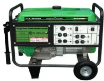
natural_image
Green portable electricity generator with control panel and wheels (no visible text or symbols)LF6500(E)-CSA-CA

text_image
CANYI Seats Temporary Generation Power Supply 100-1000kW Fuel CellLF8000(E)-CSA-CA
(CSA-CA)Indicatesth isunitisCSA (Canadian Compliant) And CARB Cered (California Compliant)
(E) Indicates this unit is equipped with Electric Start
SPÉCIFICATIONS
GÉNÉRATRICE PORTABLES ENERGY STORM
:
Voltage :
Débit de pointe*:
Débit maximal**:
Débit nominal***:
Batterie (non comprise):
1 ch.
S.O.
1 ch.
1 ch.
text_image
AC120V/30A 30A CIRCUIT BREAKER ON OFF ENG.SW. START OFF AC120V/240V/30A 30A AC120V/20A 20A AC120V/29A 20A AC120V/29A 20A GNDLF8000E CSA-CA

text_image
Energy Storm Generator/Generatuer/Generador Distributed by: Litan Power USA Customer Service 1-866-471-7464 www.litanpowerusa.com EPA - CARB Certified Equipped with Low Oil Warning System Automatically shoots all engine when oil might get out DANGER A DANGER DANGER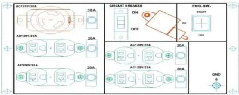
text_image
AC120V/30A 30A CIRCUIT BREAKER IENQ.SW. START ON OFF AC120V/20A 20A AC120V/20A 20A AC120V/20A 20A GNDLF6500 and LF6500E CSA-CA
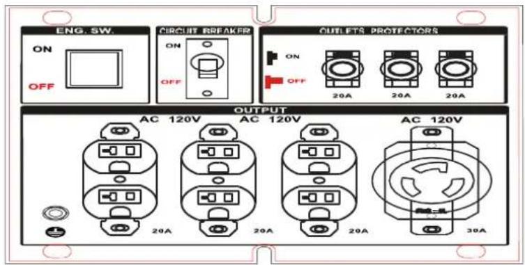
text_image
ENG. SW. ON OFF CIRCUIT BREAKER ON OFF OUTLETS PROTECTORS ON OFF 20A 20A 20A OUTPUT AC 120V AC 120V AC 120V 20A 20A 20A 30ALF3500 and LF3500E CSA-CA
text_image
Technical diagram of a device with numbered components, likely illustrating a mechanical or electrical assembly.ENTRETIEN DES BOUGIES D'ALLUMAGE
text_image
Technical diagram of a mechanical assembly with numbered componentsENTRETIEN DU SYSTÈME D'ALIMENTATION EN CARBURANT
natural_image
Illustration of two hands holding a small object with internal components, no text or symbols present
LIFAN Power USA is proud to offer it's extensive line of LIFAN Power Equipment!!!! LIFAN Power USA is the sole distribution for LIFAN Power Equipment in the United States. LIFAN's unmatched investment in research and development ensures quality engines, generators, pressure washers, and water pumps at an extraordinary value. LIFAN continues to be an innovator and presently holds over 3,000 patents. Product performance has earned LIFAN the reputation of dependability and value in all their international markets.
LIFAN has been manufacturing and selling innovative and value driven products worldwide for over 15 years. LIFAN is distributed in over 100 countries. LIFAN is the largest privately owned company in China with sales over One-Billion Dollars annually and 14,000 employees. As the largest engine manufacturer in China, LIFAN builds more than five million small engines each year. This worldwide presence has been made possible by producing equipment that is durable, reliable, and rugged for any market.
LIFAN Power USA prides itself in standing behind all LIFAN products with our comprehensive warranty policy. LIFAN Power USA continues to offer the highest level or service and support in the industry. With proven performance and unmatched value, LIFAN Power Equipment will always keep you running.
All information in this publication is based on the latest product information available at the time of approval for printing. EquipSource, LLC reserves the right to make changes at any time without notice and without incurring any obligation. The copyright of this document belongs to EquipSource, LLC. No parts of this publication may be reproduced without the written permission of EquipSource, LLC.
For additional product information of any LIFAN Power Equipment, please visit us at our website - www.lifanpowerusa.com.
LIFAN POWER USA 2205 Industrial Park Rd. Van Buren, AR 72956 www.lifanpowerusa.com 866-471-7464
POWERED BY
LIFAN
CSA-CA-EPA CERTIFIED
ENERGY STORM SERIES