
TruFit - Pool pump Jandy - Free user manual and instructions
Find the device manual for free TruFit Jandy in PDF.
User questions about TruFit Jandy
0 question about this device. Answer the ones you know or ask your own.
Ask a new question about this device
Download the instructions for your Pool pump in PDF format for free! Find your manual TruFit - Jandy and take your electronic device back in hand. On this page are published all the documents necessary for the use of your device. TruFit by Jandy.
USER MANUAL TruFit Jandy
TruFit™ Bubbler with Pressure Check Technology
WARNING
FOR YOUR SAFETY - This product must be installed and serviced by a contractor who is licensed and qualified in pool equipment by the jurisdiction in which the product will be installed where such state or local requirements exist. The maintainer must be a professional with sufficient experience in pool equipment installation and maintenance so that all of the instructions in this manual can be followed exactly. Before installing this product, read and follow all warning notices and instructions that accompany this product. Failure to follow warning notices and instructions may result in property damage, personal injury, or death. Improper installation and/or operation may void the warranty.

Improper installation and/or operation can create unwanted electrical hazard which can cause serious injury, property damage, or death.
ATTENTION INSTALLER - This manual contains important information about the installation, operation and safe use of this product. This information should be given to the owner/operator of this equipment.
Table of Contents
Section 1. Important Safety Instructions 3
Section 2. Installing Jandy® TruFit™ Bubbler with Pressure Check Technology................................4
2.1 Installation Preparations 4
2.2 Installing the TruFit Bubbler Housing 9
2.3 Plumbing Multiple TruFit Bubblers 10
2.4 LED Light Installation 11
Section 3. Winterizing. 11
Section 4. Troubleshooting.. 11
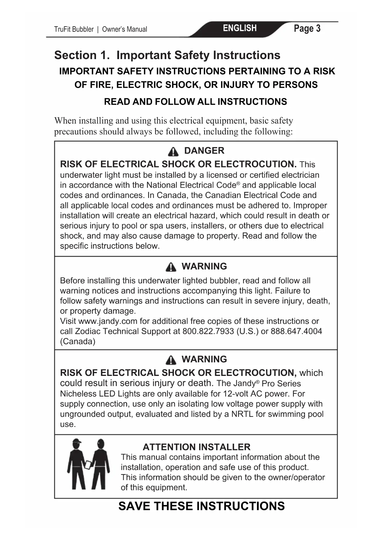
Section 1. Important Safety Instructions
IMPORTANT SAFETY INSTRUCTIONS PERTAINING TO A RISK OF FIRE, ELECTRIC SHOCK, OR INJURY TO PERSONS
READ AND FOLLOW ALL INSTRUCTIONS
When installing and using this electrical equipment, basic safety precautions should always be followed, including the following:

DANGER
RISK OF ELECTRICAL SHOCK OR ELECTROCUTION. This underwater light must be installed by a licensed or certified electrician in accordance with the National Electrical Code and applicable local codes and ordinances. In Canada, the Canadian Electrical Code and all applicable local codes and ordinances must be adhered to. Improper installation will create an electrical hazard, which could result in death or serious injury to pool or spa users, installers, or others due to electrical shock, and may also cause damage to property. Read and follow the specific instructions below.

WARNING
Before installing this underwater lighted bubbler, read and follow all warning notices and instructions accompanying this light. Failure to follow safety warnings and instructions can result in severe injury, death, or property damage.
Visit www.jandy.com for additional free copies of these instructions or call Zodiac Technical Support at 800.822.7933 (U.S.) or 888.647.4004 (Canada)

WARNING
RISK OF ELECTRICAL SHOCK OR ELECTROCUTION, which could result in serious injury or death. The Jandy® Pro Series Nichesless LED Lights are only available for 12-volt AC power. For supply connection, use only an isolating low voltage power supply with ungrounded output, evaluated and listed by a NRTL for swimming pool use.

ATTENTION INSTALLER
This manual contains important information about the installation, operation and safe use of this product. This information should be given to the owner/operator of this equipment.
Section 2. Installing Jandy® TruFit™ Bubbler with Pressure Check Technology
The Bubbler Housing is pre-assembled for easy connection to a water supply line (1) and a conduit connection for the Jandy HydroCool Nicheless Pool Light cord to run through.
NOTE: Be sure to read the entire Owner's Manual completely and carefully to assure you understand the system before you start your installation.
NOTE: Do NOT use pipe dope for installation.
NOTE: Install plumbing before any electrical wiring.
2.1 Installation Preparations
The conduit for the low voltage supply cord (12Vac) can be run directly to a Junction Box where Light(s) connections and Low Voltage wires from the Transformer (sized correctly) are made. To reduce the risk of bad connections and unwanted voltage drops, all Power Cords on lights should run directly to the Low Voltage Transformer.
To ensure maximum safety, only use a low voltage that is listed or certified by a Nationally Recognized Testing Laboratory (NRTL) as compliant with UL 379, Standard for Power Units for Fountain, Swimming Pool, and Spa Luminaires.
The TruFit Bubbler is designed so that the lens of the tube is approximately 4^ - 8^ (10-20 cm) underwater, but can be deeper as long as the water supply can be increased.
Keep in mind that the deeper the lens is underwater the less lighting effect will be above the water. Water flow should be adjusted to the desired plume while Jandy® HydroCool Nicheless Pool Light is set to the desired color mode. Use the table below to determine the approximate plume height for each lens.
| 1/2” LENS PLUME HEIGHT | ||||||
| Water Depth 2 | 4” 6” | 8” | 10” | 12” | ||
| 5 GPM 9” 6.5” | 4” | |||||
| 10 GPM 22.5” | 12” | 8” 7” | 4.5” | 4” | ||
| 15 GPM | 59” | 28” | 16.5” | 10.5” | 8” | 7.5” |
| 20 GPM | 49” 28” | 16” 12.5” | 1.5” | |||
| 25 GPM | 45.5” | 27.5” | 18” | 16” | ||
| 3/4” LENS PLUME HEIGHT | ||||||
| Water Depth 2 | " 4" 6" | 8" | 10" | 12" | ||
| 10 GPM 8" 6" | 4.5" | |||||
| 15 GPM 15.5" | 10.5" 7 | 5" 6" 5" | 4.5" | |||
| 20 GPM | 27" | 17" | 11" | 9" | 7.5" | 6.5" |
| 25 GPM | 41" | 26.5" | 16.5" | 12.5" | 11" | 8" |
| 30 GPM | 61" | 36" | 23" | 16.5" | 13" | 11" |
| 35 GPM | 49" | 34" | 22.5" | 17" | 14.5" | |
| 40 GPM | 64" | 49" | 30.5" | 22" | 17.5" | |
| 45 GPM | 61" | 39" | 27" | 21" | ||
| 50 GPM | 51" | 34.5" | 26.5" | |||
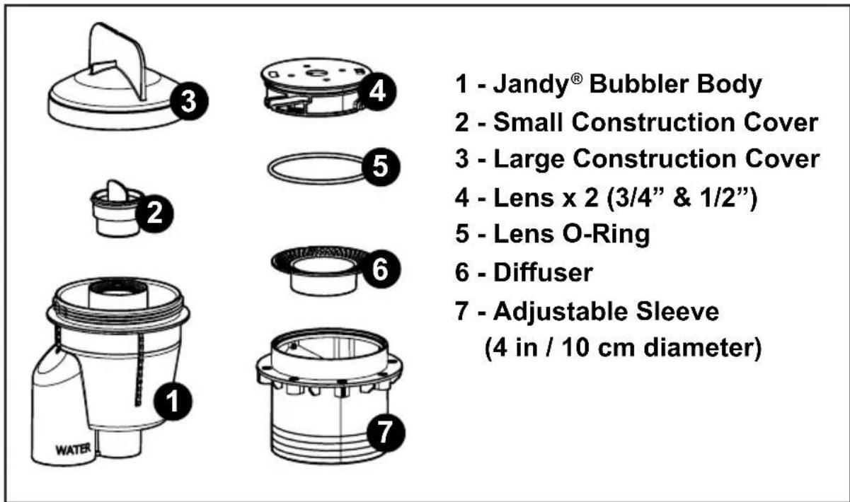
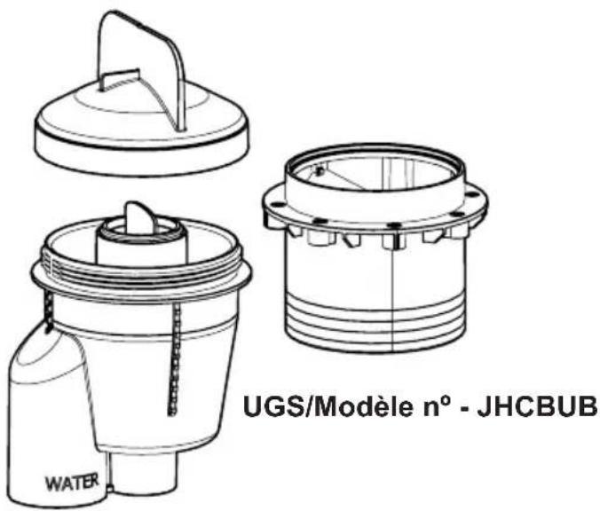
Figure 1. Package Contents
The TruFit^TM Bubbler body comes with the Large Construction Cover pre-assembled and ready to pressure test.
Inside the TruFit Bubbler Body - a Small Construction Cover has already been installed. Do not remove this until the Bubbler Body is ready to have the light installed.
NOTE: The TruFit Bubbler is designed for gunite pools; fiberglass and vinyl pool installation available with an accessory kit. (SKU/Model # JHCBUB-V)
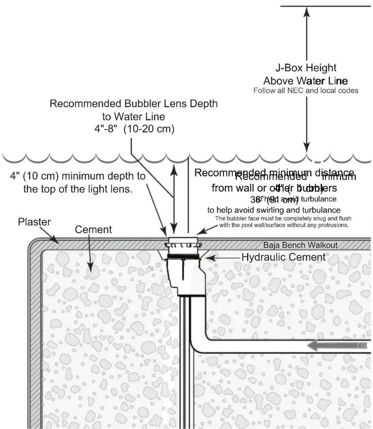
Figure 2. Bubbler Installation Guidelines
The top of the cap (A) indicates the maximum finish height of the bubbler. There is 1" of downward adjustability.
The lower indicator on the cap (B) indicates the minimum finish height of the bubbler. This uses the full 1^ of downward adjustability.
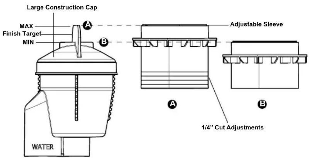
Figure 3. Large Construction Cap and Adjustable Sleeve
The TruFit™ Bubbler has an adjustable sleeve that can easily be cut to fit the desired level. The large construction cap is designed to be a guide for showing the range of adjustability.
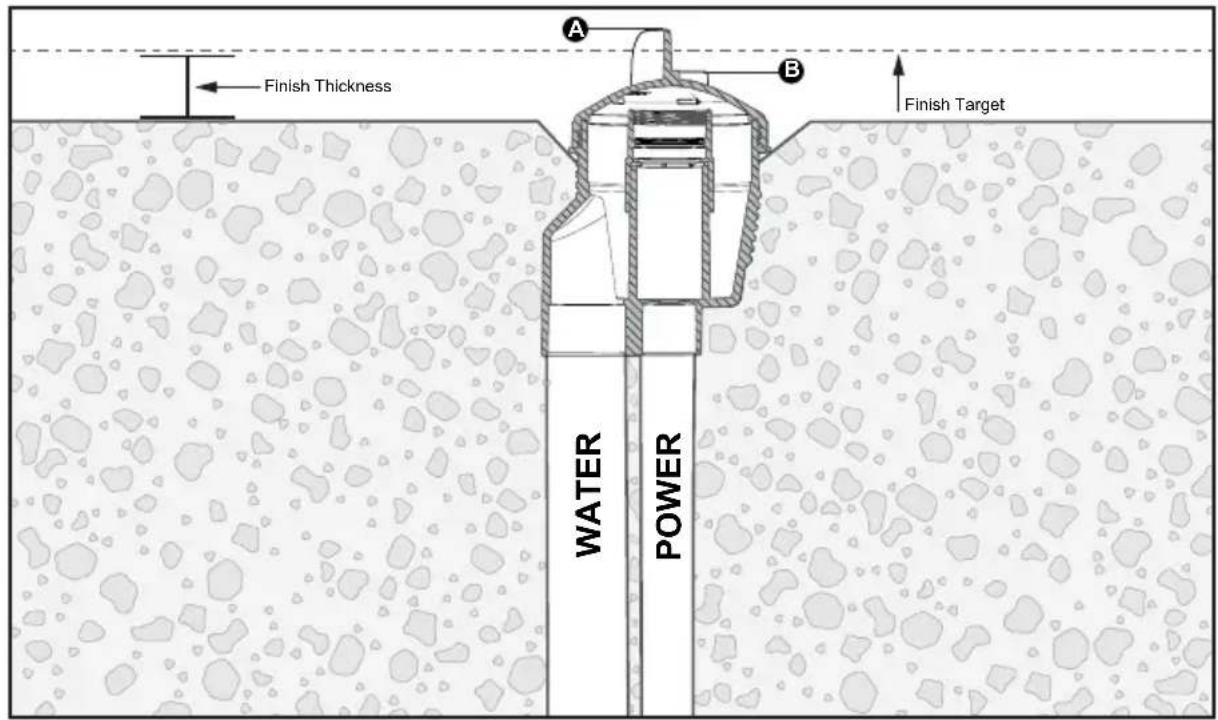
Figure 4. Bubbler Housing Installation Level
2.2 Installing the TruFit ™ Bubbler Housing
- The TruFit Bubbler is designed to be installed during the gunite phase of pool building.
- Two conduits should be run to the Bubbler body:
A. 1.5^ PVC Pipe for water supply and
B. 1" conduit for Pool Light Power Cord.
NOTE: Do NOT use 90 degree fittings. Only 45 degree or sweep elbows.
- The 1.5" PVC pipe supplying the water to the Bubbler should have a gate valve or ball valve installed to adjust the water supply flow to create desired water/lighting effect.
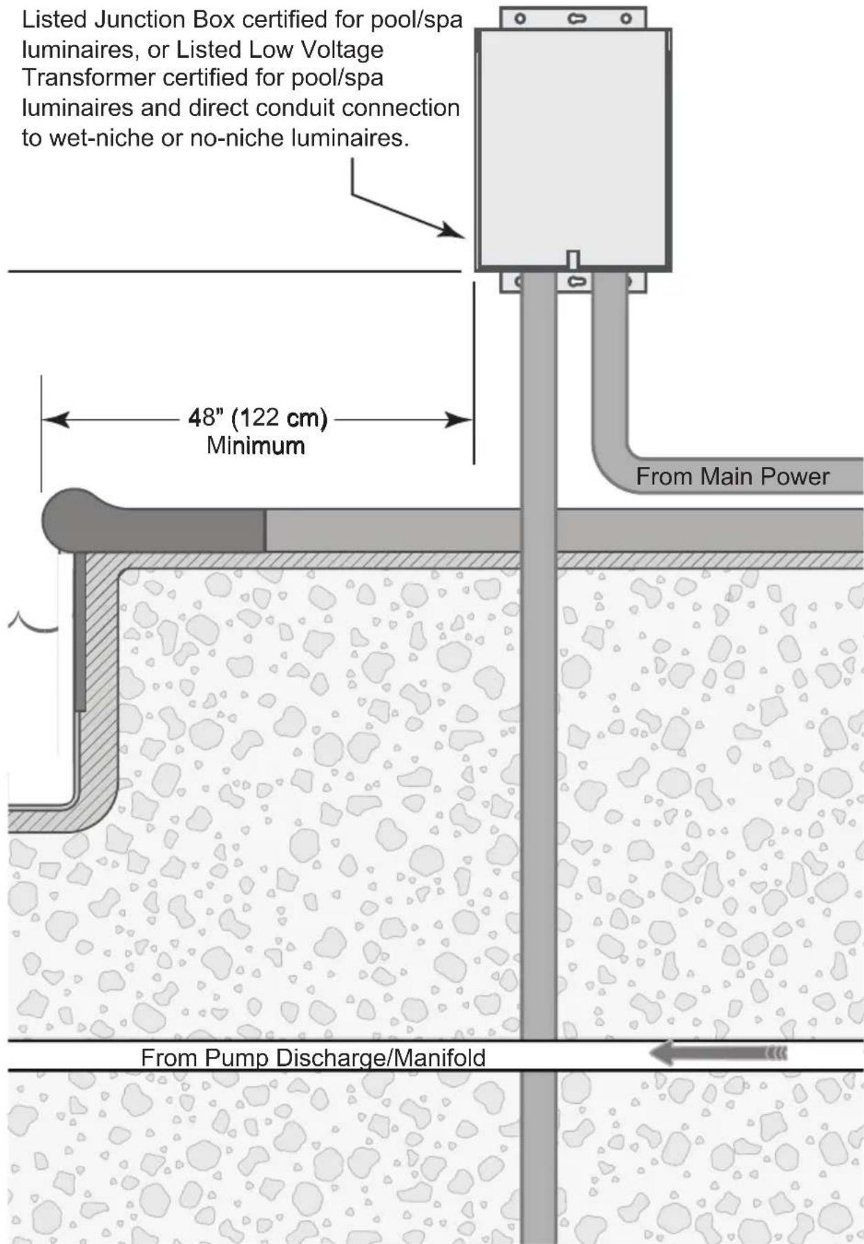
- Conduit for the TruFit Bubbler power cord must run from the bubbler directly to a listed Junction Box certified for pool/spa luminaires, or Listed Low Voltage Transformer certified for pool/spa luminaires and direct conduit connection to wet-niche or no-niche luminaires.
- With the large construction cap on, install the Bubbler Housing onto the pipe so that the desired finished surface is above the lower indicator (B) and bellow the top of the cap (A). See figure 4
Important: After gunite you need to "cove" around the TruFit Bubbler Housing. This is so that the Large Construction Cover can be removed and the adjustable sleeve can be installed and trimmed to be flush with the interior surface.
- Dig a cove around the top of the TruFit Bubbler Housing.
- Trim Adjustable Sleeve to be flush with the interior surface.
NOTE: Threaded inserts on the adjustable sleeve are only used for vinyl/ fiberglass installations.
8. Install the Small Construction Cover before plastering. This ensures the threads remain clean and no debris falls into the Bubbler Housing.
9. Backfill the "cove" area around the Bubbler Housing. After plastering, remove the Small Construction Cover.
NOTE: Leave the O-ring in the bubbler body when removing the Small Construction Cover to seal the pool light when it is installed.
- Install the Jandy® HydroCool Nicheless Pool Light (see Section 2.4).
- Install the diffuser into the adjustable sleeve. Rotate until the cutouts on the diffuser align with the pins on the adjustable sleeve.
- Select the lens for the desired water effect. Wrap the lens O-Ring around the lens groove. Install the lens into the adjustable sleeve and rotate the lens until it is secured.
2.3 Plumbing Multiple TruFit™ Bubblers
When installing multiple bubblers it is advised that a looped manifold system be implemented to provide independent water flow control to each of the bubblers on the system. See Figure 1.
- Plumb an adjustable ball or gate valve to supply flow to the manifold assembly.
- If necessary install reducer bushings to bring the supply lines to each bubbler down to the required 1.5" supply size.
- Plumb an adjustable ball or gate valve on each branch of the manifold.
- Use the individual ball valves to adjust the plume height on each of the bubblers to your preference.
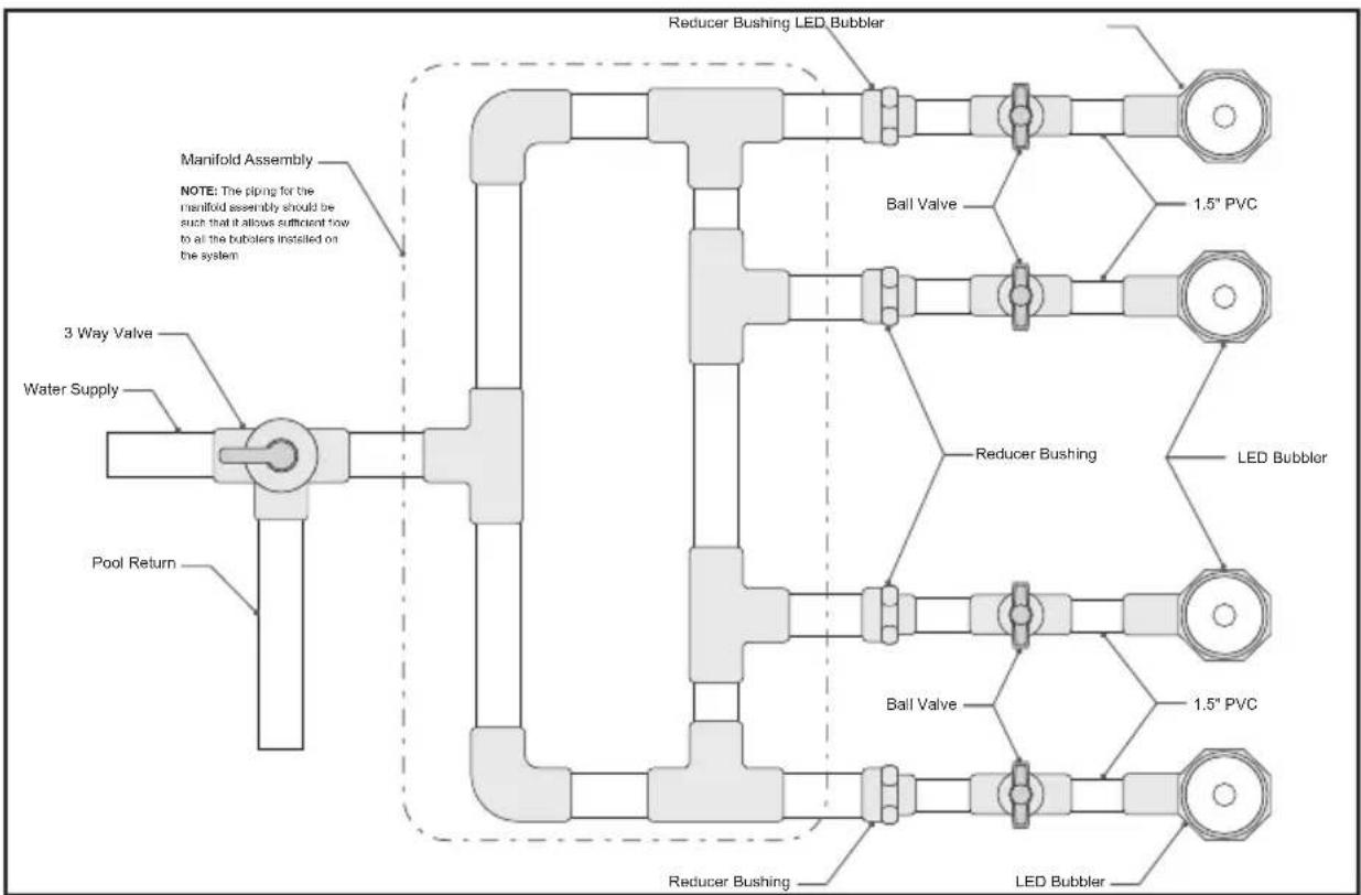
Figure 5. Looped Manifold Plumbing
2.4 LED Light Installation
The Jandy TruFit™ Bubbler with Pressure Check Technology is designed to be fitted with a Jandy® HydroCool Nichesless Pool Light. Once the pressure tests have been completed and the Small Construction Cover has been removed, you are ready to install the Jandy HydroCool Nichesless Light into the Bubbler Housing.
- Feed the power cable through the housing and conduit to the power source. Allow 18"-24" slack for service loop.
- Place the Light into the Bubbler and tighten into the threaded housing.
- See the Jandy HydroCool Nicheless light Owner's Manual for light installation instructions.
Section 3. Winterizing
Do not keep the winter water level at the level of the light. Make certain that the water level is left at least 4" or more above or below the light depending on the pool's other winterization needs. Consult a Local Swimming Pool Professional for proper winterization. At NO TIME should there be water removed from the pool without checking ground water tables.
Section 4. Troubleshooting
Use the troubleshooting information in the following table for suggestions.
| Symptom Problem Corrective Action | ||
| All lights fail to illuminate Lignts are not receiving power | Check 120VAC power supply into transformer. Check for 12VAC output at transformer. If 120 volts was used in the installation, damage may result and will not be covered under warranty. | |
| One or more lights are dim, blinking or not working | Poor connection or improper wire gauge | Separate each light and independently wire 12V to the single light only. Repeat this process on each light. If junction box is being used, check for proper connection of light cord. Verify that the correct wire gauge is being used between the transformer and junction box. |
| Colored lights out of synch | Improper voltage supply or poor connection to the light | Verify that proper wire connections are being achieved for the lights that are out of synch. Reset all the lights to white by turning lights OFF for five (5) seconds, then turning ON. |
Zodiac Pool Systems LLC
2882 Whiptail Loop # 100
Carlsbad, CA 92010
1.800.822.7933 | Jandy.com
Zodiac Pool Systems Canada, Inc.
3365 Mainway, Unit 2 Burlington
ON L7M 1A6
1.888.647.4004 | Jandy.ca

ETL LISTED CONFORMS TO UL STD 676
CERTIFIED TO CAN/CSA C22.2 NO.89
©2021 Zodiac Pool Systems LLC. All rights reserved. ZODIAC® is a registered trademark of Zodiac International, S.A.S.U., used under license. All other trademarks are the property of their respective owners.
H0666000 REVD
Zodiac Pool Systems LLC
2882 Whiptail Loop # 100, Carlsbad, CA 92010
Jandy.com | 1.800.822.7933
Zodiac Pool Systems Canada, Inc.
3365 Mainway, Bureau 2 Burlington, ON L7M 1A6
Jandy.ca | 1.888.647.4004

HOMOLOGUE ETL CONFORME A LA NORME UL STD 676
HOMOLOGUE CAN/CSA C22.2 NO.89
Zodiac Pool Systems LLC
2882 Whiptail Loop # 100, Carlsbad, CA 92010
Jandy.com | 1.800.822.7933
Zodiac Pool Systems Canada, Inc.
3365 Mainway, Unit 2 Burlington, ON L7M 1A6
Jandy.ca | 1.888.647.4004

INCLUDE EN ETL
CUMPLE
UL STD 676
CERTIFICACION
CAN/CSA C22.2 NO.89