CXI500NN - Heating Jandy - Free user manual and instructions
Find the device manual for free CXI500NN Jandy in PDF.

User questions about CXI500NN Jandy
0 question about this device. Answer the ones you know or ask your own.
Ask a new question about this device
Download the instructions for your Heating in PDF format for free! Find your manual CXI500NN - Jandy and take your electronic device back in hand. On this page are published all the documents necessary for the use of your device. CXI500NN by Jandy.
USER MANUAL CXI500NN Jandy
Installation & Operation Manual
Models: 500, 650, 750
⚠ WARNING: If the information in these instructions is not followed exactly, a fire or explosion may result causing property damage, personal injury or death.
-- Do not store or use gasoline or other flammable vapors and liquids in the vicinity of this or any other appliance.
-- WHAT TO DO IF YOU SMELL GAS
- Do not try to light any appliance.
- Do not touch any electrical switch; do not use any phone in your building.
- Immediately call your gas supplier from a neighbor's phone. Follow the gas supplier's instructions.
- If you cannot reach your gas supplier, call the fire department.
-- Installation and service must be performed by a qualified installer, service agency, or the gas supplier.

text_image
do not use any phone in your er from a neighbor's phone. as. ier, call the fire department. e performed by a qualified supplier.
WARNING:
This manual supplies information for the installation, operation, and servicing of the appliance. It is strongly recommended that this manual and the Jandy® CXi™ Pool Heater Service Manual be reviewed completely before proceeding with an installation. Perform steps in the order given. Failure to comply could result in severe personal injury, death, or substantial property damage.
Save this manual for future reference.
Contents
HAZARD DEFINITIONS 2
PLEASE READ BEFORE PROCEEDING 3
SAFETY INFORMATION 4
THE JANDY® CXI™ -- HOW IT WORKS 5-6
RATINGS....7
- DETERMINE UNIT LOCATION
Location of Unit 8
Indoor Clearances from Combustible Construction ..... 8
Non-Combustible / Combustible Flooring 8
Freeze Protection 8
Location....9
Hydronic Systems Anti-freeze 9
Outdoor Pool Heater Installation 9
Combustion and Ventilation Air 9
Combustion Options 9 - 11
- VENTING
Before You Begin 12
Vent System Options 13
General Venting Information 14
Conventional Negative Draft Venting 15-17
Vertical DirectAire Venting 18-20
Sidewall Venting 21-23
Horizontal DirectAire Venting 24
Direct Venting 25-31
Outdoor Installation 32
- GAS CONNECTIONS
Connecting to Gas Supply 33
Gas Pressure Test 33
Checking Manifold Gas Pressure 33
Gas Piping 33
Gas Connection 33-34
Combination Gas Valves 34
Checking Gas Supply Pressure 35
- WATER CONNECTIONS
Circulating Pump 36
Minimum Pump Performance 37
Heat Exchanger 37
Auxiliary Mixed Water Limit Control 37
Piping Diagrams 38-40
Pumped Automatic Bypass 41
Outdoor Operation: 3-Way Valve Cover 41
Automatic Bypass Valve Cover Installation 41
Manual Operation of the 3-Way Automatic Bypass ..... 41
Relief Valve 42
Automatic Chlorinator and Chemical Feeders 42
Water Flow Switch 42
Pump Purge Delay 42
Service Indicator Option 42
- ELECTRICAL CONNECTIONS
General Information 43
3-Way Automatic Bypass Valve Wiring 43
Pool Heater Operating Control Module 44-46
Wiring of the Cascade 46
- STARTUP
Pre-Start Checklist 47
Starting the Filter System 47
Check for Gas Leaks 47
Check/Control Water Chemistry 47
Freeze Protection 47-48
Check Thermostat Circuit(s) 48
Placing the Pool Heater in Operation ....48-50
Sequence of Operation 54
Jandy® CXi™ Control Module 55-56
Status Display Screens 57-58
-
MAINTENANCE 59-63
-
CONNECTION DIAGRAM 64-65
-
LADDER DIAGRAM 66-67
-
START-UP CHECKLIST 69
Revision Notes ...... Back Cover
Hazard definitions
The following defined terms are used throughout this manual to bring attention to the presence of hazards of various risk levels or to important information concerning the life of the product.

DANGER indicates an imminently hazardous situation which, if not avoided, will result in death or serious injury.

WARNING indicates a potentially hazardous situation which, if not avoided, could result in death or serious injury.

CAUTION indicates a potentially hazardous situation which, if not avoided, may result in minor or moderate injury.

CAUTION used without the safety alert symbol indicates a potentially hazardous situation which, if not avoided, may result in property damage.

NOTICE indicates special instructions on installation, operation, or maintenance that are important but not related to personal injury or property damage.
Please read before proceeding
Special instructions
NOTICE
This is a gas appliance and should be installed by a licensed electrician and/or certified gas supplier. Service must be performed by a qualified service installer, service agency or the gas supplier.

If the information in these instructions is not followed exactly, a fire or explosion may result causing property damage, personal injury, or death.
This appliance MUST NOT be installed in any location where gasoline or flammable vapors are likely to be present, unless the installation is such to eliminate the probable ignition of gasoline or flammable vapors.

Improper installation, adjustment, alteration, service or maintenance can cause injury or property damage. Refer to this manual for assistance or additional information, consult a qualified installer, service agency or the gas supplier.
Checking equipment –
Upon receiving equipment, check for signs of shipping damage. Pay particular attention to parts accompanying the appliances which may show signs of being hit or otherwise being mishandled. Verify total number of pieces shown on packing slip with those actually received. In case there is damage or a shortage, immediately notify the carrier.
Do not use this appliance if any part has been under water. The possible damage to a flooded appliance can be extensive and present numerous safety hazards. Any appliance that has been under water must be replaced.
NOTICE
The ceramic fiber material used in this appliance is an irritant; when handling or replacing the ceramic materials it is advisable that the installer follow these safety guides.
REMOVAL OF COMBUSTION CHAMBER LINING OR BASE PANELS:
■ Avoid breathing dust and contact with skin and eyes.
- Use NIOSH certified dust respirator (N95). This type of respirator is based on the OSHA requirements for cristobalite at the time this document was written. Other types of respirators may be needed depending on the job site conditions. Current NIOSH recommendations can be found on the NIOSH website at http://www.cdc.gov/niosh/homepage.html. NIOSH approved respirators, manufacturers, and phone numbers are also listed on this website.
- Wear long-sleeved, loose fitting clothing, gloves, and eye protection.
■ Apply enough water to the combustion chamber lining to prevent airborne dust.
■ Remove the combustion chamber lining from the appliance and place it in a plastic bag for disposal.
• NIOSH stated First Aid:
Eye: Irrigate immediately.
Breathing: Fresh air.
WARNING
The combustion chamber insulation in this appliance contains ceramic fiber material. Ceramic fibers can be converted to cristobalite in very high temperature applications. The International Agency for Research on Cancer (IARC) has concluded, “Crystalline silica in the form of quartz or cristobalite from occupational sources is carcinogenic to humans (Group 1).” Normal operating temperatures in this appliance are below the level to convert ceramic fibers to cristobalite. Abnormal operating conditions would have to be created to convert the ceramic fibers in this appliance to cristobalite.
The ceramic fiber material used in this appliance is an irritant; when handling or replacing the ceramic materials it is advisable that the installer follow these safety guidelines.
Warranty –
Factory warranty (shipped with unit) does not apply to units improperly installed or improperly operated.
Experience has shown that improper installation or system design, rather than faulty equipment, is the cause of most operating problems.
- Excessive water hardness causing a lime/scale build-up in the copper tube is not the fault of the equipment and is not covered under the manufacturer's warranty (see Water Treatment and Water Chemistry).
- Excessive pitting and erosion on the inside of the copper tube may be caused by too much water velocity through the tubes and is not covered by the manufacturer's warranty (see Pool heater Flow Rates for flow requirements).
Safety information
⚠️ Owner warning –
The information contained in this manual is intended for use by qualified professional installers, service technicians, or gas suppliers.
NOTICE
Consult and follow all local Building and Fire Regulations and other Safety Codes that apply to this installation. Consult local gas utility company to authorize and inspect all gas and flue connections.
Please read before proceeding Safety information (cont'd)
A gas appliance that draws combustion air from the equipment room where it is installed must have a supply of fresh air circulating around it during burner operation for proper gas combustion and proper venting.

Should overheating occur or the gas supply fail to shut off, do not turn off or disconnect the electrical supply to the pump. Instead, shut off the gas supply at a location external to the appliance.
Prevention of freezing –
Heat exchangers and headers damaged by freezing are not covered by warranty.
See Section 6, Operating Information - Freeze Protection for more information.
Spa and hot tub safety –
The following safety rules must be observed while operating spa or hot tub.
- Spa or hot tub water temperatures should never exceed 104^ F ( 40^ C). A temperature of 100^ F ( 38^ C) is considered safe for a healthy adult. Special caution is suggested for young children.
- Drinking of alcoholic beverages before or during spa or hot tub use can cause drowsiness which could lead to unconsciousness and subsequently result in drowning.
- Pregnant women beware! Soaking in water above 102^ F ( 39^ C) can cause fetal damage during the first three months of pregnancy (resulting in birth of a brain-damaged or deformed child). Pregnant women should observe the 100^ F ( 38^ C) maximum rule.
- Before entering the spa or hot tub, users should check the water temperature with an accurate thermometer; spa or hot tub thermostats may err in regulating water temperatures by as much as 4^ F ( 2^ C).
- Persons with a medical history of heart disease, circulatory problems, diabetes or blood pressure problems should obtain their physician's advice before using spas or hot tubs.
- Persons taking medications which induce drowsiness, such as tranquilizers, antihistamine or anticoagulants, should not use spas or hot tubs.
Codes
The equipment shall be installed in accordance with those installation regulations in force in the local area where the installation is to be made. These shall be carefully followed in all cases. Authorities having jurisdiction shall be consulted before installations are made. In the absence of such requirements, the installation shall conform to the latest edition of the National Fuel Gas Code, ANSI Z223.1/NFPA 54 and/or Natural Gas and Propane Installation Code, CSA B149.1. All pool heater heat exchanger construction conforms to the latest edition of the ASME Boiler and Pressure Vessel Code, Section IV.
WARNING
To minimize the possibility of serious personal injury, fire or damage to your unit, never violate the following safety rules.
- Pool heaters are heat producing appliances. To avoid damage or injury, do not store materials against the pool heater or the vent-air intake system. Use proper care to avoid unnecessary contact (especially children) with the pool heater and vent-air intake components.
- Never cover your pool heater, lean anything against it, store trash or debris near it, stand on it, or in any way block the flow of fresh air to your pool heater.
- UNDER NO CIRCUMSTANCES must flammable materials such as gasoline or paint thinner be used or stored in the vicinity of this pool heater, vent-air intake system or any location from which fumes could reach the pool heater or vent-air intake system.
- This pool heater is only for use with the type of gas indicated on the rating plate.
- If you smell gas, shut off the gas supply:
- Do not try to light any appliance;
- Do not touch any electrical switch; do not use any telephone in your building;
- Immediately call your gas supplier from a neighbor's telephone. Follow the gas supplier's instructions;
- If you cannot reach your gas supplier, call the fire department.
-
This appliance is a high efficiency pool heater which has been designed to operate scale-free and trouble free for many years. Particular attention should be directed to the following items:
-
Correct piping to the pool filter system with specified pipe materials and size;
- Electrical interconnection of the pool heater controls, bypass pump and filter pump to ensure continuous circulation;
- Proper venting;
-
Water chemistry.
-
Follow all clearances from combustibles contained in this manual.
-
Appliance surfaces become hot during operation. Be careful not to touch hot surfaces. Keep all adults, children, and animals away from an operating pool heater. Severe burns can occur.
-
This pool heater must have an adequate supply of fresh air during operation for proper gas combustion and venting.
-
Make sure all exhaust venting is properly installed and maintained. Improper venting of this pool heater could lead to increased levels of carbon monoxide.
-
Do not use this pool heater if any part has been under water. Immediately call a qualified service technician to replace the pool heater. The possible damage to a flooded pool heater can be extensive and present numerous safety hazards. Any appliance that has been under water must be replaced.
-
Do not alter this pool heater in any way. Any change to this pool heater or its controls can be dangerous.
The Jandy® CXi™ - How it works...
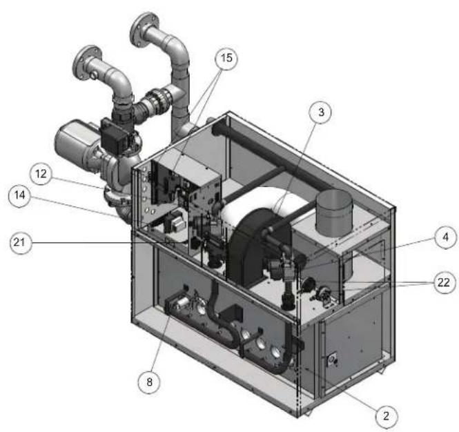
1. Heat exchanger
The heat exchanger allows system water to flow through specially designed tubes for maximum heat transfer. The glass lined headers and copper fined tubing are encased in a jacket that contains the combustion process.
2. Heat exchanger access cover
The heat exchanger access cover is a galvanized steel door which allows access for service, maintenance, and removal of the heat exchanger from inside the combustion chamber.
3. Blower
The blower pulls in and injects air into the individual burners along with gas from the gas manifold where the mix is burned inside the combustion chamber.
4. Gas valve
The referenced gas valves have a dual purpose; changing the gas supply pressure to manifold pressure, and the reference side of the gas valve is designed to allow chamber pressure to change the volume of gas through the valve. This is not a design to compensate for gas supply pressure issues.
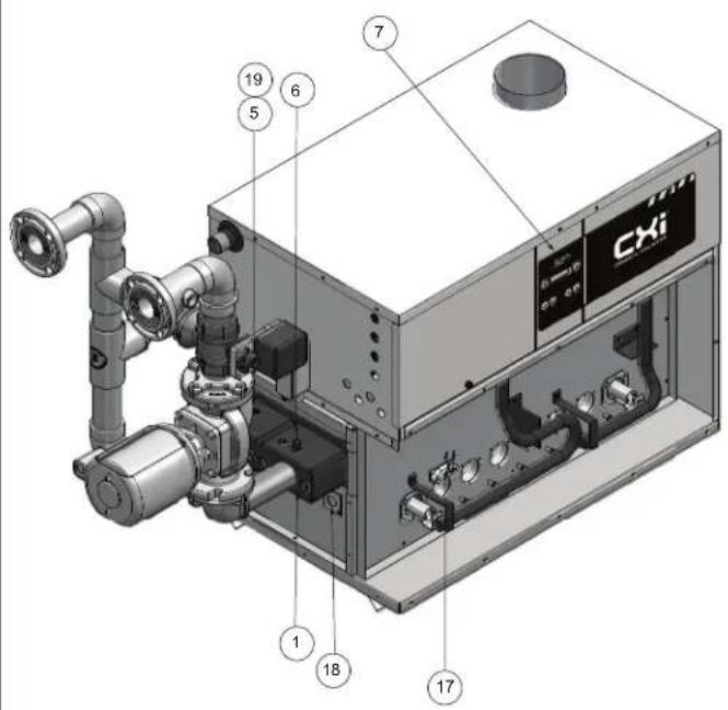
5. Outlet/limit temperature sensor
This 4-wire limit rated sensor monitors the outlet temperature to ensure safe operation. The appliance will adjust its firing rate to maintain water temperatures below the maximum allowable outlet temperature.
6. Inlet temperature sensor
This 2-wire sensor monitors the inlet temperature. The appliance will adjust the position of the 3-way valve to maintain the inlet water temperature above the minimum allowable inlet temperature.
7. Electronic display
The electronic display consists of 6 buttons and a two-line 16-character liquid crystal display used to monitor the operation of the heater as well as enter and view the programming of the main control board.
8. Burner
The burner is a ported stainless steel construction which uses a gas air mix to operate at a fixed input. Banks of burners turn on or off to vary the firing rate.
9. Pool supply/limit sensor (not shown)
This 4-wire limit rated sensor monitors the temperature of the water being supplied to the pool to ensure safe operation. The appliance will shut down if the maximum allowable pool supply temperature is exceeded.
10. Pool return sensor (not shown)
This 2-wire sensor is the controlling sensor and it monitors the temperature of the pool water. The appliance will stage to maintain pool temperature set point and turn off when set point is met.
11. Gas supply pipe
The gas supply pipe on this appliance is 1 1/4 or 2" (depending on model) diameter NPT. Please reference the National Fuel Gas Code charts for connection details.
12. Control Module
The Control Module is the main control for the appliance. This module contains the programming that operates the blower, gas valve, and pumps in addition to other programmable features.
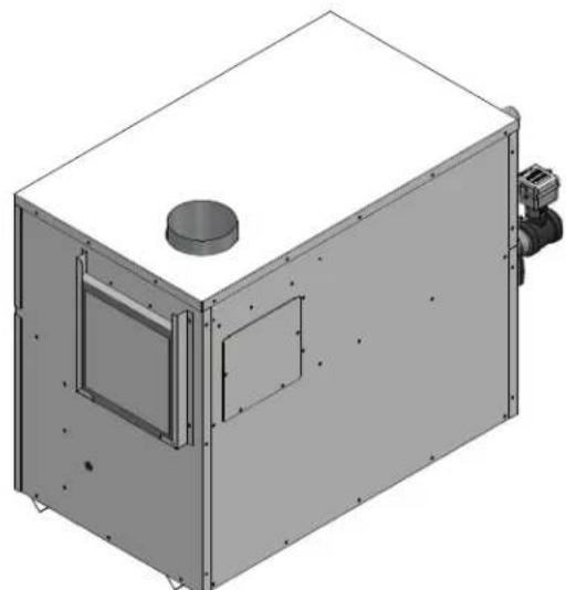
13. Air intake
Fresh air for combustion is drawn through a filter provided at the air intake, located at either the rear or right side of the appliance.
14. Line voltage terminal strip
The line voltage terminal strip provides a location to connect all of the line voltage (120 VAC) contact points to the unit.
15. Low voltage connection board
The low voltage connection board provides a location to connect all of the low voltage devices to the appliance. This is where most of the external safety controls are connected.
16. Front doors - upper and lower
The front doors provide access to the gas train as well as the blower, burners and other key components for service and maintenance.
17. Hot surface igniter (HSI)
The hot surface igniter is a device that is used to ignite the air/gas mixture as well as monitor the performance of the flame during operation. This device acts as a flame sense electrode.
18. Flame inspection window (sight glass)
The flame inspection windows, located on either side of the appliance, allow for visual inspection of the burners and flame during operation.
19. Manual reset high limit sensor
This device monitors the outlet water temperature to ensure safe operation. If the temperature exceeds its setting (field adjustable), it will break the control circuit, shutting the appliance down. Manual reset is performed through the display.
20. Relief valve
The relief valve is a safety device that ensures the maximum pressure of the appliance is not exceeded. Pool heaters operate on temperature and pressure and are shipped standard as 150 PSI and 210°F (98.9°C).
21. Power switch
The power switch is used to engage and disengage power to the appliance on the 120 VAC circuit.
22. Air pressure switch
The air pressure switch is a safety device which ensures proper blower operation. The air pressure switch is wired in series with the low voltage control circuit in such a way that if the fan does not engage or shuts down prematurely the device will break the control circuit and the unit will shut down.
23. Flow switch
The flow switch is a safety device that ensures flow through the heat exchanger during operation. This appliance is low mass and should never be operated without flow. The flow switch makes contact when flow is detected and allows the unit to operate. If flow is discontinued during operation for any reason the flow switch will break the control circuit and the unit will shut down.
24. Drain port(s)
Location from which the heat exchanger can be drained. The drain ports are located underneath the front header.
25. Manual shutoff valve (not shown)
Manual valve used to isolate the unit from the gas supply.
The Jandy® CXi™ - How it works...

text_image
11 16 16 16 CXi 24Models CXi500, CXi650, CXi750 Front View

text_image
13 20 23Models CXi500, CXi650, CXi750 Rear View
text_image
Technical diagram of a mechanical device with numbered components for identificationModels CXi500, CXi650, CXi750 Right Side (inside unit)
text_image
CXi 19 5 6 7 18 17Models CXi500, CXi650, CXi750 Left Side (inside unit)
Ratings


H
| Model Number | Specifications | |||
| Appliance Water Content Gallons | Water Connections Gas Connections | Air / Vent Sizes(Note 1) | ||
| CXi500 1.7 2" | -1/4" 6" | |||
| CXi650 2.0 2" | -1/4" 8" | |||
| CXi750 2.1 2" | -1/4" 8" | |||
NOTICE
Maximum allowed working pressure is located on the rating plate.
Notes:
- Jandy® CXi™ pool heaters require special gas venting. Use only the vent materials and methods specified in the Jandy® CXi™ Pool Heater Installation and Operation Manual.
- The Jandy® CXi™ is orificed for operation up to 2000 feet altitude, and including up to 4,500 feet, with no field adjustments. The appliance will de-rate by 4% for each 1000 feet above sea level up to 4,500 feet. Consult the factory for installations above 4,500 feet elevation.
1 Determine unit location Location of unit
This unit meets the safe lighting performance criteria with the gas manifold and control assembly provided, as specified in the ANSI standards for gas-fired units and CSA/ANSI Z21.56 CSA 4.7-2019 - latest edition.
- Maintain all clearances from combustible construction when locating appliance. See Clearances from Combustible Construction, this page.
- Locate the appliance so that if water connections should leak, water damage will not occur. When such locations cannot be avoided, it is recommended that a suitable drain pan, adequately drained, be installed under the unit. The pan must not restrict combustion airflow. Under no circumstances is the manufacturer to be held responsible for water damage in connection with this unit, or any of its components.
- The appliance must be installed so that the ignition system components are protected from water (dripping, spraying, rain, etc.,) during appliance operation and service (circulator replacement, control replacement, etc.,).
- Appliances located in a residential garage and in adjacent spaces that open to the garage and are not part of the living space of a dwelling unit must be installed so that all burners and burner ignition devices have a minimum clearance of not less than 18" (46 cm) above the floor. The appliance must be located or protected so that it is not subject to physical damage by a moving vehicle.
- DO NOT install this appliance in any location where gasoline or flammable vapors are likely to be present.
- The appliance must be installed on a level floor.
- Combustible floor installation: a. Models CXi500, CXi650 and CXi750 require an approved floor kit for installation on combustible flooring (reference Table 1A).
- DO NOT install this appliance directly on carpeting or other combustible material.
- Maintain required clearances from combustible surfaces, reference the Indoor Clearances from Combustible Construction Section, this page.
- For outdoor models, you must install an optional vent cap. Instructions for mounting the vent cap are included in the venting section of this manual. Do not install outdoor models directly on the ground. You must install the outdoor unit on a concrete, brick, block, or other non-combustible pad. Outdoor models have additional special location and clearance requirements. See Outdoor Installation Venting, page 32. A wind proof cabinet protects the unit from weather.
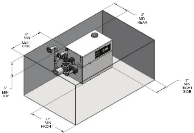
Indoor clearances from combustible construction
Maintain minimum specified clearances for adequate operation. Allow sufficient space for servicing pipe connections, pump and other auxiliary equipment, as well as the unit. See rating plate for specific service clearance requirements.
Right Side 3" (7.5 cm)
Rear 3" (7.5 cm) (3" min. from any surface)*
Left Side 6" (15 cm) (24" (0.61 m) suggested for service)
Front Alcove* (30" (0.76 m) suggested for service)
Top 3" (7.5 cm)
Flue 1" (25.4 mm)
Hot Water Pipes 1" (25.4 mm)
*An Alcove is a closet without a door. Thirty-six inches (36") to rear required for outdoor installation.
Note: No additional clearance is needed on the right side of the unit for the observation port. An observation port is located on both the right and left side of the unit.
Figure 1-1_Indoor clearances from combustible construction
text_image
6" MIN LEFT SIDE 3" MIN TOP 30" MIN FRONT 3" MIN REAR 3" MIN RIGHT SIDENOTICE Clearances from combustible construction are noted on the appliance rating plate.
| TABLE - 1A COMBUSTIBLE FLOOR KITS | |
| Model | Kit Number |
| CXi500 | 100136977 |
| CXi650 | 100136978 |
| CXi750 | 100136979 |
Freeze protection
Installations are not recommended in areas where the danger of freezing exists. You must provide proper freeze protection for outdoor installations, units installed in unheated mechanical rooms or where temperatures may drop to the freezing point or lower. If freeze protection is not provided for the system, a low ambient temperature alarm is recommended for the mechanical room. Damage to the unit by freezing is non-warrantable.
1 Determine unit location
Anytime the inlet temperature drops below 45^ F, the control turns on the pump contact. If the inlet temperature is below 37^ F, and the unit is in the ON Mode, the first stage will fi re.
Location
Locate indoor pool heaters in a room having a temperature safely above freezing [32°F (0°C)].

A mechanical room operating under a negative draft pressure may experience a down draft in the flue of a pool heater when it is not firing. The cold outside air pulled down the flue may freeze a heat exchanger. This condition must be corrected to provide adequate freeze protection.
Hydronic systems anti-freeze
Freeze protection for a pool heater using an indirect coil can be provided by using hydronic system antifreeze. Follow the appliance manufacturers instructions. Do not use undiluted or automotive type antifreeze (see page 42).
Outdoor pool heater installation
A snow screen should be installed to prevent snow and ice accumulation around the unit or its venting system.
Combustion and ventilation air
Provisions for combustion and ventilation air must be in accordance with Air for Combustion and Ventilation, of the latest edition of the National Fuel Gas Code, ANSI Z223.1, in Canada, the latest edition of CAN/CGA-B149 Installation Code for Gas Burning Appliances and Equipment, or applicable provisions of the local building codes.
Provide properly-sized openings to the equipment room to assure adequate combustion air and proper ventilation when the unit is installed with conventional venting or sidewall venting.
Combustion air options

Under no circumstances should the equipment room ever be under a negative pressure. Particular care should be taken where exhaust fans, attic fans, clothes dryers, compressors, air handling units, etc., may take away air from the unit.
This unit has four combustion air options.
1. Outside Combustion Air, No Ducts
You can direct outside combustion air to this unit using either one or two permanent openings.
One Opening
The opening must have a minimum free area of one square inch per 3000 Btu input (7 cm ^2 per kW). You must locate this opening within 12" (30 cm) of the top of the enclosure (see FIG. 1-2).

natural_image
Pure technical diagram of a mechanical or electrical setup without any text, numbers, or symbolsFigure 1-2_Outside Combustion Air - Single Opening
Two Openings
The combustion air opening must have a minimum free area of one square inch per 4000 Btu/hr input (5.5 cm ^2 per kW). You must locate this opening within 12" (30 cm) of the bottom of the enclosure (see FIG. 1-3).
The ventilation air opening must have a minimum free area of one square inch per 4000 Btu/hr input (5.5 cm ^2 per kW). You must locate this opening within 12" (30 cm) of the top of the enclosure.
natural_image
Simple line drawing of a utility pole with support structure and equipment (no text or symbols)Figure 1-3_Outside Combustion Air - Two Openings
2. Outside Combustion Air, Using Ducts
You can direct outside combustion air to this unit using two air ducts to deliver the air to the mechanical room (see FIG. 1-5).
Each of the two openings must have a minimum free area of one square inch per 2000 Btu input (11cm ^4 per kW).
3. Combustion Air from Interior Space
You can direct combustion air to this unit using air from an adjoining interior space. You must provide two openings from the mechanical room to the adjoining room (see FIG. 1-4).
Each of the two openings must have a net free area of one square inch per 1000 Btu input (22cm ^2 per kW), but not less than 100 square inches (645cm ^2 ).
natural_image
Pure technical diagram of a mechanical or electrical assembly without any text, numbers, or symbolsFigure 1-4_Combustion Air from Interior Space
1 Determine unit location

natural_image
Diagram of a utility pole structure with ladder and support frame (no text or symbols)Figure 1-5_Outside Combustion Air Through Ducts
4. Outside Combustion Air - Using Direct Venting
With this option, you can connect combustion air vent piping directly to the unit. See the information under Direct Venting starting on page 25 for specific information regarding this option.
All dimensions are based on net free area in square inches. Metal louvers or screens reduce the free area of a combustion air opening a minimum of approximately 25%. Check with louver manufacturers for exact net free area of louvers. Where two openings are provided, one must be within 12" (30 cm) of the ceiling and one must be within 12" (30 cm) of the floor of the equipment room. Each opening must have a minimum net free area as specified in TABLE 1B, this page. Single openings shall be installed within 12" (30 cm) of the ceiling.
CAUTION
The combustion air supply must be completely free of any flammable vapors that may ignite or chemical fumes which may be corrosive to the appliance. Common corrosive chemical fumes which must be avoided are fluorocarbons and other halogenated compounds, most commonly present as refrigerants or solvents, such as Freon, trichlorethylene, perchlorethylene, chlorine, etc. These chemicals, when burned, form acids which quickly attack the heat exchanger finned tubes, headers, flue collectors, and the vent system. The result is improper combustion and a non-warrantable, premature unit failure.
| TABLE - 1BMINIMUM RECOMMENDED COMBUSTIONAIR SUPPLY TO EQUIPMENT ROOM | |||||||
| Model Number | *Outside Air from2 Openings Directly fromOutdoors | *Outside Air from1 Opening Directlyfrom Outdoors, in2 | Inside Air from2 Ducts Delivered fromOutdoors | Inside Air from2 Ducts Delivered fromInterior Space | |||
| Top Opening, in2 | Bottom Opening, in2 | Top Opening, in2 | Bottom Opening, in2 | Top Opening, in2 | Bottom Opening, in2 | ||
| CXi500 | 125(806 cm2) | 125(806 cm2) | 167(1077 cm2) | 250(1613 cm2) | 250(1613 cm2) | 500(3226 cm2) | 500(3226 cm2) |
| CXi650 | 163(1052 cm2) | 163(1052 cm2) | 217(1400 cm2) | 325(2097 cm2) | 325(2097 cm2) | 650(4194 cm2) | 650(4194 cm2) |
| CXi750 | 188(1213 cm2) | 188(1213 cm2) | 250(1613 cm2) | 375(2420 cm2) | 375(2420 cm2) | 750(4839 cm2) | 750(4839 cm2) |
*Outside air openings shall directly communicate with the outdoors. When combustion air is drawn from the outside through a duct, the net free area of each of the two openings must have twice (2 times) the free area required for Outside Air/2 Openings. The above requirements are for the pool heater only; additional gas fired appliances in the equipment room will require an increase in the net free area to supply adequate combustion air for all appliances.
1 Determine unit location (continued)
Exhaust fans
Any fan or equipment which exhausts air from the mechanical room may deplete the combustion air supply and/or cause a down draft in the venting system. Spillage of flue products from the venting system into an occupied living space can cause a very hazardous condition that must be immediately corrected. If a fan is used to supply combustion air to the mechanical room, the installer must make sure that it does not cause drafts which could lead to nuisance operational problems with the pool heater.
Vertical DirectAire ^™ , Horizontal DirectAire ^™ , and Direct Vent venting systems have specific requirements for combustion air ducts from the outside which are directly connected to the unit. See the requirements for combustion air duct in the venting section.
NOTICE
Use of filters having MERV (Minimum Efficiency Reporting Value) ratings higher than 4 is not recommended. Higher efficiency low-micron filters can limit combustion air leading to either nuisance problems or potential component damage if used over prolonged periods of time. Filters having a MERV rating of 5 to 6 may be used on a limited basis during the construction phase of a project provided they are replaced once filter loading becomes apparent. After the construction phase is completed, it is recommended that the filter be changed to a 4 or lower MERV disposable type filter.
Combustion air filter
This unit has a standard air filter located at the combustion air inlet. This filter helps ensure clean air is used for the combustion process. Check this filter every month and replace when it becomes dirty. The filter size on Models CXi500, CXi650 and CXi750 is 12" x 12" x 1" (30.5 cm x 30.5 cm x 2.5 cm). You can find these commercially available filters at any home center or HVAC supply store.
For convenience and flexibility, you can direct the combustion air inlet from either the back or right side of the unit. To arrange the combustion air inlet for side entry, follow the steps below:
- Remove the metal panel from the unit's side wall (see FIG. 1-6).
- Remove screws from the air filter/bracket assembly.
- Move the filter/bracket assembly from the rear of unit to the side opening (see FIG. 1-7).
- Attach filter/bracket assembly to the unit's side using the pre-drilled screw holes.
- Attach the metal panel to the rear combustion air opening to seal it off.

natural_image
3D rendering of a mechanical enclosure with mounting flanges and a cylindrical component (no text or symbols visible)Figure 1-6_Metal Panel Covering Side Combustion Air Inlet
natural_image
3D rendering of a mechanical enclosure with mounting flanges and a central cylindrical component (no text or symbols visible)Figure 1-7_Moving Air Filter / Bracket Assembly from Rear of Unit to Side
NOTICE
During construction the air filter should be checked more frequently to ensure it does not become clogged with combustion dirt and debris.
CAUTION
Sustained operation of an appliance with a clogged filter may result in nuisance operational problems, bad combustion, and non-warrantable component failures.
2 Venting
BEFORE YOU BEGIN
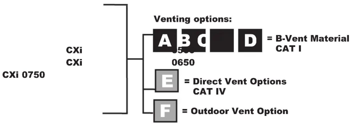
Identify your appliance's vent system:
This manual covers venting requirements for CAT I models and CAT IV vent materials. Be sure to correctly identify the type of vent system your appliance requires before proceeding.
flowchart
graph TD
    A["CXi 0750"] --> B["Venting options:"]
    B --> C["A = B-Vent Material CAT I"]
    B --> D["D = 500"]
    B --> E["E = Direct Vent Options CAT IV"]
    B --> F["F = Outdoor Vent Option"]

DANGER
Failure to use correct venting materials can result in loss of life from flue gas spillage into working or living space.
Venting Category Definitions: (Reference National Fuel Gas Code ANSI Z223.1)
CAT I: Negative pressure non-condensing
An appliance that operates with a non-positive vent static pressure with a vent gas temperature that avoids excessive condensate production in the vent.
CAT IV: Positive pressure condensing
An appliance that operates with a positive vent static pressure with a vent gas temperature that may cause excessive condensate production in the vent.
CAT IV Flue pipe materials
The following manufacturers supply flue materials suitable for these models when installed as CAT IV. All materials are made with AL29-4C stainless steel.
Heat-Fab Inc., Saf-T CI Vent with AL29-4C stainless steel
Protech Systems Inc., Fas N Seal Vent with AL29-4C stainless steel
Metal-Fab Inc., Corr/Guard Vent with AL29-4C stainless steel
Or other listed Category IV vent systems suitable for a condensing, positive pressure, gas fired appliance.
A Category IV flue MUST have all vent joints and seams sealed gastight and have provisions for a drain to properly collect and dispose of condensate that may occur in the venting system.
2 Venting (continued)
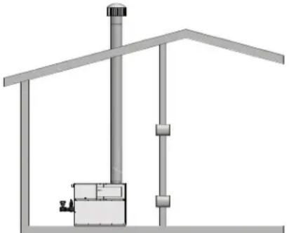
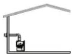
Vent system options: (Note: Installations shown below are representative, actual installations may vary from those shown.)

This option uses a vertical rooftop flue termination with air supplied from the equipment room - see page 15.
CONVENTIONAL NEGATIVE DRAFT VENTING
text_image
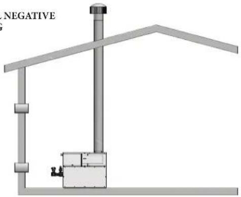
NEGATIVE
This option uses a powered vent assembly to exhaust the flue products out a sidewall with air supplied by a pipe from the sidewall - see page 24.
HORIZONTAL DIRECTAIRE
VENTING
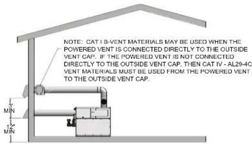
text_image
NOTE: CAT I B-VENT MATERIALS MAY BE USED WHEN THE POWERED VENT IS CONNECTED DIRECTLY TO THE OUTSIDE VENT CAP. IF THE POWERED VENT IS NOT CONNECTED DIRECTLY TO THE OUTSIDE VENT CAP. THEN CAT IV - AL29-4C VENT MATERIALS MUST BE USED FROM THE POWERED VENT TO THE OUTSIDE VENT CAP.
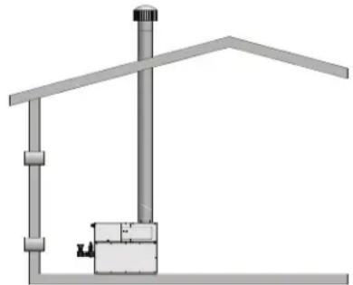
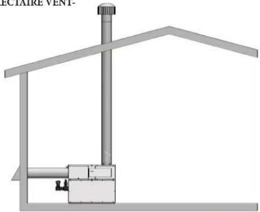
This option uses a vertical conventional vent for flue products with air supplied by a pipe from the sidewall or rooftop - see page 18.
VERTICAL DIRECTAIRE VENTING
natural_image
Technical diagram of a house structure with ventilation duct and support frame (no text or symbols)
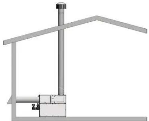
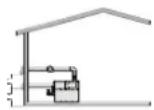
This option uses a sealed AL29-4C flue and a separate combustion air pipe to the outdoors. This system terminates both the flue and combustion air inlet in the same pressure zone - see page 25.

text_image
3' MIN 12" MIN
This option uses a powered vent assembly to exhaust the flue products out a sidewall vent termination with air supplied from the equipment room - see page 21.
SIDEWALL VENTING
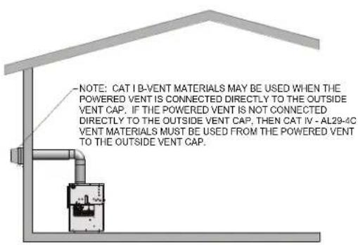
text_image
NOTE: CAT I B-VENT MATERIALS MAY BE USED WHEN THE POWERED VENT IS CONNECTED DIRECTLY TO THE OUTSIDE VENT CAP. IF THE POWERED VENT IS NOT CONNECTED DIRECTLY TO THE OUTSIDE VENT CAP, THEN CAT IV - AL29-4C VENT MATERIALS MUST BE USED FROM THE POWERED VENT TO THE OUTSIDE VENT CAP.
This option uses the installation of a special air inlet / vent cap on top of the unit - see page 32.
OUTDOOR VENTING

natural_image
3D technical illustration of a venting machine with mounting flanges and control panel (no text or symbols)2 Venting
General information
You must supply adequate combustion and ventilation air to this unit. You must provide minimum clearances for the vent terminal from adjacent buildings, windows that open, and building openings. Follow all requirements set forth in the latest edition of the National Fuel Gas Code, ANSI Z223.1, in Canada, the latest edition of CAN/CGA Standard B149 Installation Code for Gas Burning Appliances and Equipment or applicable local building codes. Vent installations for connection to gas vents or chimneys must be in accordance with “Venting of Equipment” of the above-mentioned standards.
NOTICE
Examine the venting system at least once each year. Check all joints and vent pipe connections for tightness. Also check for corrosion or deterioration. If you find any problems, correct them at once.
Venting support
Support horizontal portions of the venting system to prevent sagging. Provide an upward slope of at least 1/4 inch per foot (21mm/m) on all horizontal runs from the unit to the vertical flue run or to the vent terminal on sidewall venting installations.
Do not use an existing chimney as a raceway if another appliance or fireplace is vented through the chimney. The weight of the venting system must not rest on the unit. Provide adequate support of the venting system. Follow all local and applicable codes. Secure and seal all vent connections. Follow the installation instructions from the vent material manufacturer.
Barometric damper location
Any venting system option that requires a barometric damper must adhere to the following directions for optimum performance. The preferred location for the barometric damper is in a tee or collar installed in the vertical pipe rising from the unit's flue outlet. The barometric damper MUST NOT be installed in a bull head tee installed on the unit's flue outlet. The tee or collar containing the barometric damper should be approximately three feet vertically above the connection to the unit's flue outlet. This location ensures that any positive velocity pressure from the unit's internal combustion fan is dissipated and the flue products are rising due to buoyancy generated from the temperature of the flue products. Adjust the weights on the damper to ensure that draft is maintained within the specified range.
| TABLE - 2AFLUE AND AIR INLET PIPE SIZES | ||
| MODEL FLUE SIZE AIR INLET SIZE | ||
| CXi500 6" 6" | ||
| CXi650 8" 8" | ||
| CXi750 8" 8" | ||
| *Minimum diameter for air inlet pipe. Installer may increase diameter one pipe size for ease of installation, if needed. | ||
2 Venting (continued)

Conventional negative draft venting - see page 13.

Before installing a venting system, follow requirements found in the General Venting section.
This option uses Type-B double-wall flue outlet piping. The blower brings in combustion air. The buoyancy of the heated flue products cause them to rise up through the flue pipe. The flue outlet terminates at the rooftop.
Negative draft
The negative draft in a conventional vent installation must be within the range of 0.02 to 0.08 inches w.c. to ensure proper operation. Make all draft readings while the unit is in stable operation (approximately 2 to 5 minutes).
Connect the flue vent directly to the flue outlet opening on the top of the unit. No additional draft diverter or barometric damper is needed on single unit installations with a dedicated stack and a negative draft within the specified range of 0.02 to 0.08 inches w.c. If the draft in a dedicated stack for a single unit installation exceeds the maximum specified draft, you must install a barometric damper to control draft. Multiple unit installations with combined venting or common venting with other Category I negative draft appliances require each pool heater to have a barometric damper installed to regulate draft within the proper range.
Do not connect vent connectors serving appliances vented by natural draft (negative draft) to any portion of a mechanical draft system operating under positive pressure. Connecting to a positive pressure stack may cause flue products to be discharged into the living space causing serious health injury.
Flue outlet piping
With this venting option, you must use Type-B double-wall vent materials. Vent materials must be listed by a nationally-recognized test agency for use as vent materials. Make the connections from the unit vent to the outside stack as direct as possible with no reduction in diameter. Use the National Fuel Gas Code venting tables for double-wall vent to properly size all vent connectors and stacks. Follow the vent manufacturer's instructions when installing Type-B vents and accessories, such as firestop spacers, vent connectors, thimbles, caps, etc.
Provide adequate clearance to combustibles for the vent connector and firestop.
When planning the venting system, avoid possible contact with plumbing or electrical wiring inside walls, ceilings, and floors. Locate the unit as close as possible to a chimney or gas vent.
Avoid long horizontal runs of the vent pipe, 90^ elbows, reductions and restrictions.
No additional draft diverter or barometric damper is required on single unit installations with a dedicated stack and a negative draft maintained between 0.02 to 0.08 inches w.c.
Common Venting Systems
You can combine the flue with the vent from any other negative draft, Category I appliance. Using common venting for multiple negative draft appliances requires you to install a barometric damper with each unit. This will regulate draft within the proper range. You must size the common vent and connectors from multiple units per the venting tables for Type-B double-wall vents in the latest edition of the National Fuel Gas Code, ANSI Z223.1 and/or CAN/CGA-B149 Installation Code.
Common venting systems may be too large when an existing unit is removed.
At the time of removal of an existing appliance, the following steps shall be followed with each appliance remaining connected to the common venting system placed in operation, while other appliances remaining connected to the common venting system are not in operation.
- Seal any unused opening in the common venting system.
- Visually inspect the venting system for proper size and horizontal pitch. Make sure there is no blockage or restriction, leakage, corrosion and other unsafe conditions.
- If possible, close all building doors and windows. Close all doors between the space in which the appliances remaining connected to the common venting system are located and other building spaces.
2 Venting
- Turn on clothes dryers and any other appliances not connected to the common venting system. Turn on any exhaust fans, such as range hoods and bathroom exhausts, so they will operate at maximum speed. Do not operate a summer exhaust fan.
- Close fireplace dampers.
- Place in operation the unit being inspected. Follow the lighting instructions. Adjust thermostat so unit will operate continuously.
- Test for spillage at the draft hood/relief opening after 5 minutes of main burner operation. Use the flame of a match or candle, or smoke from a cigarette, cigar or pipe.
- After making sure that each appliance remaining connected to the common venting system properly vents when tested as above, return doors, windows, exhaust fans, fireplace dampers and other gas burning appliances to their previous conditions of use.
- Correct any improper operation of the common venting system so that the installation conforms to the latest edition of the National Fuel Gas Code, ANSI Z223.1, in Canada, the latest edition of CAN/CGA-B149 Installation Code for Gas Burning Appliances and Equipment. When resizing any portion of the common venting system, resize to approach the minimum size as determined using the appropriate tables of the latest edition of the National Fuel Gas Code, ANSI Z223.1, in Canada, the latest edition of CAN/CGA-B149 Installation Code for Gas Burning Appliances and Equipment.
Masonry chimney installations
A masonry chimney must be properly sized for the installation of a high efficiency gas-fired appliance. Venting of a high efficiency appliance into a cold or oversized masonry chimney can result in operational and safety problems. Exterior masonry chimneys, with one or more sides exposed to cold outdoor temperatures, are more likely to have venting problems. The temperature of the flue products from a high efficiency appliance may not be able to sufficiently heat the masonry structure of the chimney to generate proper draft. This will result in condensing of flue products, damage to the masonry flue/tile, insufficient draft and possible spillage of flue products into an occupied living space. Carefully inspect all chimney systems before installation.

Do not vent this unit into a masonry chimney without a sealed stainless steel liner system. Any breaks, leaks, or damage to the masonry flue/tile will allow the flue products to leak from the chimney and into occupied living spaces. This could cause serious injury or death due to carbon monoxide poisoning and other harmful flue products.

Check with local code officials to determine code requirements or the advisability of using a masonry chimney with a sealed corrosion-resistant liner system.
Inspection of a masonry chimney
A masonry chimney must be carefully inspected to determine its suitability for the venting of flue products. A clay-tile-lined chimney must be structurally sound, straight and free of misaligned tile, gaps between liner sections, missing sections of liner or any signs of condensate drainage at the breaching or clean out. If there is any doubt about the condition of a masonry chimney, it must be relined with a properly-sized and approved chimney liner system. An unlined masonry chimney must not be used to vent flue products from this high-efficiency unit. An unlined chimney must be relined with an approved chimney liner system when a new appliance is being attached to it. Metallic liner systems (Type-B double-wall or flexible or rigid metallic liners) are recommended. Consult with local code officials to determine code requirements or the advisability of using or relining a masonry chimney.
Vertical vent termination clearances and location
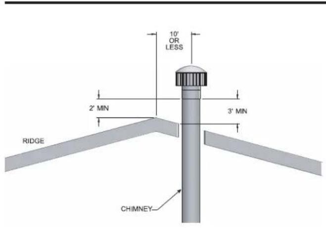
The vent terminal should be vertical and exhaust outside the building at least 2 feet (0.61 m) above the highest point of the roof within a 10 foot (3.05 m) radius of the termination.
The vertical termination must be a minimum of 3 feet (0.91 m) above the point of exit.
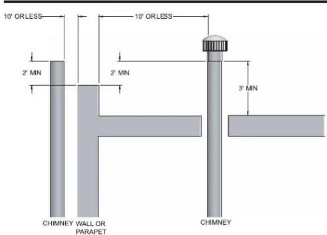
A vertical termination less than 10 feet (3.05 m) from a parapet wall must be a minimum of 2 feet (0.61 m) higher than the parapet wall.
Keep the vent cap clear of snow, ice, leaves, and debris to avoid blocking the flue.
2 Venting (continued)
text_image
10' OR LESS 2' MIN 3' MIN RIDGE CHIMNEYFigure 2-1_Vent Termination from Peaked Roof - 10 ft. or Less From Ridge

text_image
MORE THAN 10' 10' 3' MIN 2' MIN RIDGE CHIMNEYFigure 2-2_Vent Termination from Peaked Roof - 10 ft. or More From Ridge
NOTICE
Vent terminations are not shown in FIG.'s 2-1 thru 2-4. Make sure all vertical vents are installed with vent terminations recommended by the vent manufacturer.
text_image
10' ORLESS 2' MIN 10' ORLESS 2' MIN 3' MIN CHIMNEY WALL OR PARAPET CHIMNEYFigure 2-3_Vent Termination from Flat Roof - 10 ft. or Less From Parapet Wall
text_image
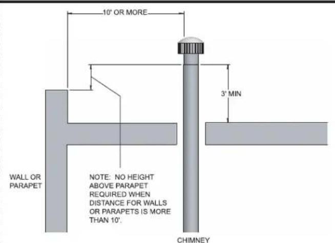
10' OR MORE 3' MIN WALL OR PARAPET NOTE: NO HEIGHT ABOVE PARAPET REQUIRED WHEN DISTANCE FOR WALLS OR PARAPETS IS MORE THAN 10'. CHIMNEYFigure 2-4_Vent Termination from Flat Roof - 10 ft. or More From Parapet Wall
2 Venting
Vertical DirectAire ^TM venting - see page 13.

NOTICE
Before installing a venting system, follow requirements found in the General Venting section.
The Vertical DirectAire ^™ vent system is the same as the Conventional Negative Draft vent system, except it pulls combustion air from the outdoors through a separate air inlet pipe. Follow all requirements in the Conventional Negative Draft Venting section on page 15.
The Vertical DirectAire™ vent system requires you to install two pipes directly to the unit; one vertical pipe with a rooftop termination for the flue products and one pipe for combustion air. For this venting option, you must purchase the DV box adapter from the appliance manufacturer. The DV box attaches to the air inlet of the unit. The pipe for combustion air attaches to the DV box (see FIG. 2-11 on page 27). Reference page 27 for a list of approved air intake materials.
Combustion air inlet piping
Locate and install the combustion air inlet cap correctly. Failure to do so can allow the discharge of flue products to be drawn into the combustion process. This can result in incomplete combustion and potentially hazardous levels of carbon monoxide in the flue products. This will cause operational problems and the spillage of flue products. Spillage of flue products can cause personal injury or death due to carbon monoxide poisoning.
The sidewall or vertical rooftop DirectAire™ combustion air supply system has specific material and installation requirements. The air inlet pipe connects directly to the unit to supply combustion air. In most installations, the combustion air inlet pipe will be a dedicated system with one air inlet pipe per unit. You can combine multiple air inlets if the guidelines in Combined Air Inlet Points, page 19 are followed. The air inlet pipe will be connected to a combustion air inlet cap as specified in this section.
For normal installations, this system uses a single-wall pipe to supply combustion air from outdoors directly to the unit.
In cold climates, use a Type-B double-wall vent pipe or an insulated single-wall pipe for combustion air. This will help prevent moisture in the cool incoming air from condensing and leaking from the inlet pipe.
Length of air inlet pipe
The installed length of air inlet pipe from the unit to the outside air inlet cap must not exceed 50 equivalent feet (15.2 m). Subtract 5 feet (1.5 m) of equivalent length for each 90° elbow. Subtract 2.5 feet (0.7 m) of equivalent length for each 45° elbow.
Do not exceed the limits for the combustion air inlet piping lengths.
Sidewall air inlet
The sidewall air inlet cap is supplied in the Sidewall Air Inlet Kit. Order the kit from the appliance manufacturer. This sidewall cap supplies combustion air for a single unit only. See Table 2B, page 20, for kit numbers.
Locate the unit as close as possible to the sidewall where you will install the combustion air supply system.
natural_image
Pure technical diagram of a mechanical or structural assembly without any text, numbers, or symbolsFigure 2-5_Sidewall Combustion Air Inlet
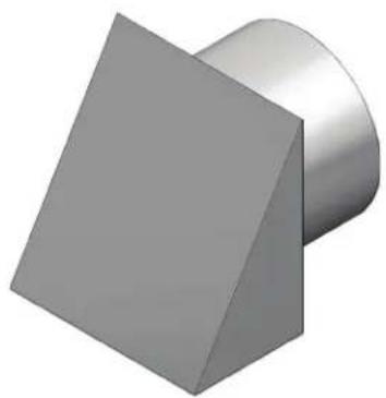
natural_image
3D geometric shapes: a gray square and a metallic cylinder (no text or symbols)Figure 2-6_Air Inlet Cap for Sidewall Termination
2 Venting (continued)
To prevent recirculation of flue products from an adjacent vent cap into the combustion air inlet, follow all applicable clearance requirements in the latest edition of the National Fuel Gas Code and/or CAN/CGA-B149 Installation Code and instructions in the Installation and Operation Manual.
Clearances
You must install the combustion air inlet cap at least one foot (0.30 m) above ground level and above normal snow levels.
The point of termination for the combustion air inlet cap must be at least 3 feet (0.91 m) below the point of flue gas termination if it is located within 10 feet (3.05 m) of the flue outlet. Make sure to properly install the air inlet cap assembly on the air inlet pipe.
Do not install the combustion air inlet cap closer than 10 feet (3.05 m) from an inside corner of an L-shaped structure.
Vertical Rooftop Air Inlet
Use the vertical air inlet terminations available from the appliance manufacturer, recommended and/or supplied by the vent manufacturer, or use two 90° elbows as described on page 28.
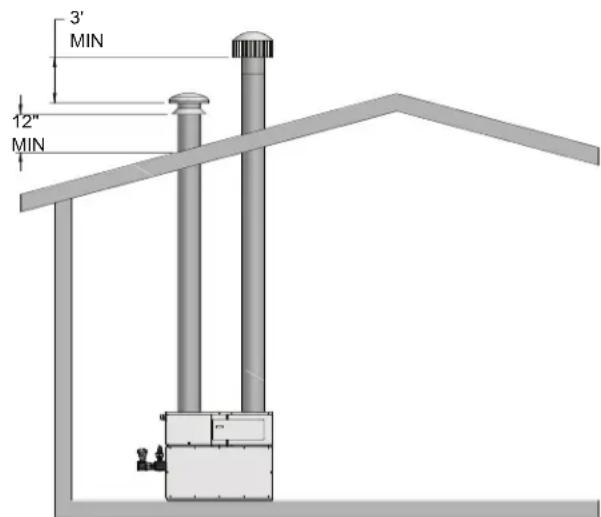
text_image
3' MIN 12" MINFigure 2-7_Rooftop Combustion Air Inlet
You must locate the air in lettermination at least 12" (30 cm) above the roof or above normal snow levels.
If the air inlet cap is within a 10-foot (3.05 m) radius of the flue outlet, the point of termination for the combustion air inlet cap must be at least 3 feet (0.91 m) below the point of flue gas termination (vent cap).
Do not install the combustion air inlet cap closer than 10 feet (3.05 m) from an inside corner of an L-shaped structure.
Combined air inlet points
The air inlet pipes from multiple pool heaters can be combined to a single common connection if the common air inlet pipe has a cross sectional area equal to or larger than the total area of all air inlet pipes connected to the common air inlet pipe.
Example: Two 10" air inlet pipes (78.5 in ^2 area each) have a total area of 157 in ^2 and will require a 15" (176.7 in ^2 area) common air inlet pipe.
The air inlet point for multiple pool heater air inlets must be provided with an exterior opening which has a free area equal to or greater than the total area of all air inlet pipes connected to the common air inlet. This exterior opening for combustion air must connect directly to the outdoors. The total length of the combined air inlet pipe must not exceed a maximum of 50 (15.2 m) equivalent feet. Subtract 5 feet (1.5 m) for each 90° elbow in the air inlet pipe. You must deduct the restriction in area provided by any screens, grills or louvers installed in the common air inlet point. These are common on the sidewall air inlet openings. Screens, grills or louvers installed in the common air inlet can reduce the free area of the opening from 25% to 75% based on the materials used.
You can terminate the combustion air pipe either horizontally with a sidewall air inlet or vertically with a rooftop air inlet. The installed length of air inlet pipe from the unit to the outside air inlet cap must not exceed 50 equivalent feet (15.2 m).
2 Venting

Only use a sidewall air inlet cap supplied by the appliance manufacturer or a rooftop air inlet cap supplied by either the vent or appliance manufacturer. Using any other air inlet cap for single unit installations or using a common air inlet cap for multiple units with insufficient free area and/or protections from wind and weather may result in operational problems and the spillage of flue products. Spillage of flue products can cause personal injury or death due to carbon monoxide poisoning.

text_image
3' MIN 12" MINFigure 2-8_Vertical DirectAire™ Installation w/Rooftop Combustion Air Inlet
For single unit installations with sidewall air inlet you must order the sidewall air inlet kit from the appliance manufacturer. The part number for each SVK kit is listed by unit size in Table 2B.
For single unit installations with rooftop air inlet (see FIG. 2-8), you must order the rooftop air inlet kit from the appliance manufacturer. The part number for each VDK kit is listed by unit size in Table 2B. Purchase the flue pipe, rooftop flue termination, and air inlet pipe locally.
There is no vent kit for combined air supply systems for multiple units. Make sure the air inlet cap is properly sized. You must purchase this cap locally.
Venting of flue products
For venting flue products vertically to the outdoors, follow all requirements in the installation instructions for conventional venting in this manual.
Follow all clearance requirements in Vertical Vent Termination Clearances and Location on page 16.
A barometric damper is not required in the flue on Vertical DirectAire ^™ installations if the draft is within the negative 0.02 to 0.08 inches w.c. required for proper operation. If the draft exceeds this range, install a barometric damper.
| TABLE - 2BDIRECTAIRE KITS | ||
| MODEL HORIZONTAL | KIT* VERTICAL KIT* | |
| CXi500 | 100169225 | 100172048 |
| CXi650 100169226 100172049 | ||
| CXi750 100169226 100172049 | ||
| *The SVK kits include a DV box adapter and sidewall air inlet cap. The VDK kits include a DV box adapter and a rooftop air inlet cap. | ||
2 Venting (continued)
Sidewall venting - see page 13.


Before installing a venting system, follow all requirements found in the General Venting section.
This option uses a powered vent assembly which pulls the flue products out of the stack. This fan generates a negative draft at the unit. Combustion air is drawn from the equipment room (see Combustion and Ventilation Air on 10).
Sidewall with fan
The sidewall fan can be mounted on the inside/outside (depending upon model) with a sidewall vent hood installed on the exterior wall. The sidewall fan and accessories are included in a venting kit provided by the appliance manufacturer. The barometric damper must be installed on the flue and adjusted to supply a negative draft within the range of 0.02 to 0.08 inches w.c. while unit is operating. See Table 2C on page 23 for kit numbers.
Flue outlet piping
With this venting option, you must use Type-B double-wall (or equivalent) vent materials. Vent materials must be listed by a nationally-recognized test agency for use as vent materials. Make the connections from the unit vent to the sidewall fan/cap as direct as possible with no reduction in diameter. Follow the vent manufacturer's instructions when installing Type-B vents and accessories, such as firestop spacers, vent connectors, thimbles, caps, etc.
When planning the venting system, avoid possible contact with plumbing or electrical wiring inside walls.
The maximum installed length of sidewall vent pipe with an induced draft fan must not exceed 100 feet (30.5 m). Subtract 5 feet (1.5 m) for each 90° elbow. Subtract 2.5 feet (0.7 m) for each 45° elbow.
Sidewall venting termination
The sidewall vent cap must be installed on an exterior sidewall. The sidewall fan/powered sidewall vent cap and accessories are included in a venting kit which is furnished by the appliance manufacturer in accordance with CSA requirements. This venting kit includes the powered sidewall fan/cap, proving switch and all necessary relays to interlock with the heaters control system.
The sidewall fan/powered vent cap must be interlocked with the units control system to start the fan on a call for heat and prove fan operation before the pool heater fires. Plug-in and terminal strip connections are provided on the unit for easy connection of the factory supplied vent kit and control package for the sidewall vent fan. See the installation instructions provided with the vent kit.
Sidewall vent termination clearances and location
Locate the bottom of the vent terminal at least 12 inches (30 cm) above grade and above normal snow levels. Locate the bottom of the vent terminal at least 7 feet (2.13 m) above grade when located adjacent to public walkways. Do not terminate directly above a public walkway.
Do not terminate the venting system in a window well, stairwell, alcove, courtyard, or other recessed area. Do not terminate the venting system below grade.
Locate vent termination at least 3 feet (0.91 m) from an inside corner of an L-shaped structure.
Provide a minimum clearance of 4 feet (1.2 m) horizontally from electric meters, gas meters, regulators, and relief equipment. Never locate vent cap above or below electric meters, gas meters, regulators, and relief equipment unless a 4 foot (1.2 m) horizontal clearance is maintained.
2 Venting
Terminate the venting system at least 3 feet (0.9 m) above any forced air inlet within 10 feet (3.05 m).
Terminate the venting system at least 4 feet (1.2 m) below, 4 feet (1.2 m) beside, or 1 foot (30cm) above any door, window, or gravity air inlet into any building.
Locate vent termination at least 8 feet (2.4 m) horizontally from any combustion air intake located above the sidewall termination cap.

Units which are shut down or will not operate may experience freezing due to convective air flow in the flue pipe, through the air inlet, or from negative pressure in the equipment room. In cold climates, operate the pump continuously to help prevent freezing of pool heater water. Provide proper freeze protection. See Freeze Protection, page 47.
Sidewall venting without fan
For Models CXi500, CXi650, and CXi750 which are approved for sidewall venting without an external power vent fan, you must install specific vent kits and venting materials (reference Table 2C on page 23 for kit numbers).
The following is a detailed explanation of Sidewall Venting Without an External Power Vent Fan installation requirements.
Flue outlet piping
Venting Guidelines
If using this venting option, a sealed AL29-4C venting system for flue products is required on all models of this appliance. This venting system operates with a positive pressure in the vent. The internal combustion air blower generates this positive pressure which operates the combustion process and also exhausts the flue products from the building.
This vent system has specific vent material and installation requirements. Only use listed sealed AL29-4C vent system materials. Follow all installation requirements. See Table 2A for proper pipe size for your unit. A list of sealed AL29-4C flue pipe manufacturers is located on page 14.
Seal all vent joints and seams gas-tight.
Drain tee installation
A drain tee must be installed in the vent pipe to collect and dispose of any condensate that may occur in the vent system. The drain tee must be installed as the first fitting after the horizontal ell on the top of the unit (see FIG. 2-9). Plastic drain tubing, sized per the vent manufacturer's instructions, shall be provided as a drain line from the tee. The drain tubing must have a trap provided by a 3" (7.6 cm) diameter circular trap loop in the drain tubing. Prime the trap loop by pouring a small quantity of water into the drain hose before assembly to the vent. Secure the trap loop in position with nylon wire ties. Use caution not to collapse or restrict the condensate drain line with the nylon wire ties. The condensate drain must be routed to a suitable drain for disposal of condensate that may occur in the direct vent system. Refer to the condensate drain installation instructions as supplied by the manufacturer of the vent material.

natural_image
Diagram of a utility room with an open structure and piping (no text or symbols)Figure 2-9_Sidewall Vent
2 Venting (continued)

Do not combine the flue from this unit with the vent from any other appliance. Do not combine flues from multiple appliances into a common vent. The flue from this unit must be a dedicated stack.
Connect the flue vent directly to the flue outlet opening on the top of the unit. Make the connections from the unit vent to the outside stack as direct as possible with no reduction in diameter. Provide adequate clearance to combustibles for the vent connector and firestop. Follow the vent manufacturer's instructions when installing sealed AL29-4C vents and accessories, such as firestop spacers, vent connectors, thimbles, caps, etc.
Provide adequate clearance to combustibles for the vent connector and firestop.
When planning the venting system, avoid possible contact with plumbing or electrical wiring inside walls, ceilings, and floors.
Locate the unit as close as possible to chimney or gas vent. When a vent system is disconnected for any reason, the flue must be reassembled and resealed according to the vent manufacturer's instructions.
The installed length of flue from the unit to the outside point of termination must not exceed 50 equivalent feet (15.2 m). Subtract 5 feet (1.5 m) of equivalent length for each 90° elbow. Subtract 2.5 feet (0.7 m) of equivalent length for each 45° elbow.
Sidewall vent termination clearances and location
Follow all sidewall venting termination information for clearances and location under Sidewall Vent Termination Clearances and Location on page 21.
| TABLE - 2CSIDEWALL VENT KITS | ||||
| MODEL | KIT(W/POWER FAN ASSY.) | MAX. VENTLENGTH | VENT TERMINATIONONLY | MAX. VENTLENGTH |
| CXi500 1001 | 69191 100 ft. 100169221 50 ft. | |||
| CXi650 1001 | 69192 100 ft. 100169222 50 ft. | |||
| CXi750 1001 | 69192 100 ft. 100169222 50 ft. | |||
2 Venting
Horizontal DirectAire™ venting (Powered Venting) - see page 13.


Before installing a venting system, follow all requirements found in the General Venting section.
The Horizontal DirectAire ^™ vent system is the same as the Sidewall Venting system, except it pulls combustion air from the outdoors through a sidewall air inlet. Follow all requirements in Sidewall Venting section on page 21.
The Horizontal DirectAire ^™ vent system requires you to install two pipes directly to the unit; one pipe for flue products and one for combustion air. Install both pipes horizontally with a sidewall termination point. For this venting option, you must purchase the DV box accessory from the appliance manufacturer. The DV box attaches to the air inlet of the unit. The pipe for combustion air attaches to the DV box (see FIG. 2-11 on page 27). Reference page 27 for a list of approved air intake materials.
Make vent connection directly to the top of the unit. No additional draft diverter or barometric damper is required on single unit installations with a dedicated stack and a negative draft maintained between 0.02 to 0.08 inches w.c.
The Horizontal DirectAire ^™ combustion air supply system has specific vent material and installation requirements. The air inlet pipe connects directly to the pool heater to supply combustion air. The combustion air inlet pipe is a dedicated system with one air inlet pipe per pool heater. You must connect the air inlet pipe to a combustion air inlet cap as specified in this section.
Combustion air supplied from outdoors must be free of contaminants (see the Combustion and Ventilation Air section on page 9).
You must order the Horizontal DirectAire™ Vent Kit for sidewall installation from the appliance manufacturer. See Table 2D for kit numbers. Each kit includes a sidewall powered vent cap fan, proving switch, controls, combustion air inlet cap to supply air to a single unit, the transition adapter to attach the field supplied single wall air inlet pipe to the unit and installation instructions. Purchase flue pipe and air inlet pipe locally.
The sidewall air inlet cap supplied in the Horizontal DirectAire™ Vent Kit is used to supply combustion air to a single pool heater. Combustion air supply pipes from multiple units can not be combined into a single air inlet pipe and inlet point.

Only use the sidewall air inlet cap recommended by the appliance manufacturer. Using another sidewall air inlet cap may result in operational problems and the spillage of flue products. Spillage of flue products can cause personal injury or death due to carbon monoxide poisoning.
Venting of flue products
For venting flue products horizontally, follow all requirements in the installation instructions for sidewall venting.
Termination point for the flue products must follow the clearance requirements in the Sidewall Venting Termination section on page 21.
For proper operation, a barometric damper is provided for Horizontal DirectAire ^™ installations. The damper will help to ensure a draft between negative 0.02 to 0.08 inches w.c.
| TABLE - 2DHORIZONTAL DIRECTAIRETM KITS | |
| MODEL KIT | |
| CXi500 100147152 | |
| CXi650 100147153 | |
| CXi750 100147153 | |
| *These kits include a barometric damper. | |
2 Venting (continued)

Direct venting - see page 13.
NOTICE
Before installing a venting system, follow all requirements found in the General Venting section.

This option uses sealed AL29-4C vent materials for the flue outlet piping and separate combustion air inlet piping. This system terminates both the flue and combustion air inlet in the same pressure zone. The flue outlet and combustion air intake may terminate at either a sidewall or the rooftop.
To use the optional Direct Vent system, you must install specific vent kits and venting materials. The following is a detailed explanation of Direct Vent installation requirements, including the components used and vent kit part numbers (reference Table 2E on page 26 for kit numbers).
Flue outlet piping
Venting Guidelines
If using this venting option, a sealed AL29-4C venting system for flue products is required on all models of this appliance. This venting system operates with a positive pressure in the vent. The internal combustion air blower generates this positive pressure which operates the combustion process and also exhausts the flue products from the building.
This vent system has specific vent material and installation requirements. Only use listed sealed AL29-4C vent system materials. Follow all installation requirements. See Table 2A, page 14 for proper pipe size for your unit.
Seal all vent joints and seams gas-tight.
Drain tee installation
A drain tee must be installed in the vent pipe to collect and dispose of any condensate that may occur in the vent system. The drain tee must be installed as the first fitting after the horizontal ell on the top of the unit (see FIG. 2-9 on page 22). Plastic drain tubing, sized per the vent manufacturer's instructions, shall be provided as a drain line from the tee. The drain tubing must have a trap provided by a 3" (7.6 cm) diameter circular trap loop in the drain tubing. Prime the trap loop by pouring a small quantity of water into the drain hose before assembly to the vent. Secure the trap loop in position with nylon wire ties. Use caution not to collapse or restrict the condensate drain line with the nylon wire ties. The condensate drain must be routed to a suitable drain for disposal of condensate that may occur in the direct vent system. Refer to the condensate drain installation instructions as supplied by the manufacturer of the vent material.

Do not combine the flue from this unit with the vent from any other appliance. Do not combine flues from multiple appliances into a common vent. The flue from this unit must be a dedicated stack.
Connect the flue vent directly to the flue outlet opening on the top of the unit. Make the connections from the unit vent to the outside stack as direct as possible with no reduction in diameter. Provide adequate clearance to combustibles for the vent connector and firestop. Follow the vent manufacturer's instructions when installing sealed AL29-4C vents and accessories, such as firestop spacers, vent connectors, thimbles, caps, etc.
Provide adequate clearance to combustibles for the vent connector and firestop.
When planning the venting system, avoid possible contact with plumbing or electrical wiring inside walls, ceilings, and floors. Locate the unit as close as possible to chimney or gas vent.
When a vent system is disconnected for any reason, the flue must be reassembled and resealed according to the vent manufacturer's instructions.
The installed length of flue from the unit to the outside point of termination must not exceed 50 equivalent feet (15.2 m). Subtract 5 feet (1.5 m) of equivalent length for each 90° elbow. Subtract 2.5 feet (0.7 m) of equivalent length for each 45° elbow.
Vertical DV venting termination
Vertical venting uses the unit's internal combustion air blower to force the flue products out of the vertically-terminated flue. You must purchase a vertical direct vent kit from the appliance manufacturer to ensure proper operation.
You must use the vent termination recommended by the vent manufacturer for vertical direct vent terminations. Follow all vertical venting termination information for clearances and location under the Vertical Vent Termination Clearances and Location section on pages 16 - 17.
2 Venting
Masonry chimney installation
Do not use a standard masonry chimney to directly vent the combustion products from this unit.
To use a masonry chimney, the chimney must use a sealed, corrosion-resistant liner system. Sealed, corrosion-resistant liner systems (single-wall, double-wall, flexible, or rigid) must be rated for use with a high efficiency, positive pressure vent system.
Corrosion-resistant chimney liner systems are typically made from a high grade stainless steel such as AL29-4C. The liner must be properly sized and fully sealed throughout the entire length. Both the top and bottom of the masonry chimney must be capped and sealed to provide a dead air space around the liner.

Do not vent this unit into a masonry chimney without a sealed stainless steel liner system. Any breaks, leaks, or damage to the masonry flue/tile will allow the positive-pressure flue products to leak from the chimney and into occupied living spaces. This could cause serious injury or death due to carbon monoxide poisoning and other harmful flue products.
NOTICE
Check with local code officials to determine code requirements or the advisability of using a masonry chimney with a sealed corrosion-resistant liner system.
Horizontal DV venting termination
Horizontal venting uses the unit's internal combustion air blower to force the flue products out of the horizontally-terminated flue.
You must purchase a horizontal direct vent kit from the appliance manufacturer to ensure proper operation. When installing the vent cap, the wall opening must provide an air space clearance of 2 inches (5.1 cm) around the flue pipe. The diameter of the opening for installation of the sidewall cap will be 4 inches (10.2 cm) larger (minimum) than the nominal diameter of the installed vent pipe to the horizontal vent cap.
Install the horizontal vent cap from the outside. Mount the vent cap to the wall using four screws or wall anchors. Seal under the screw heads with caulking. Install the Category IV vent pipe from the unit to the vent cap. See detailed instructions packed with the horizontal direct vent kit.
Horizontal Vent Termination Clearances and Location
Follow all sidewall venting termination information for clearances and location under Sidewall Vent Termination Clearances and Location, page 21.
| TABLE - 2EDIRECT VENT KITS | ||
| MODEL | HORIZONTALKIT* | VERTICALKIT* |
| CXi500 1001417 | 02 100172048 | |
| CXi650 1001417 | 03 100172049 | |
| CXi750 1001417 | 03 100172049 | |
| *These kits include a DV box adapter, air inlet cap, and a sidewall vent termination. The VDK kits include a DV box adapter and an air inlet cap. | ||
Combustion air inlet piping
The Direct Vent system requires the installation of a pipe to supply combustion air from the outdoors directly to the unit. Make sure the combustion air inlet is in the same pressure zone as the vent terminal.
In cold climates, use a Type-B double-wall vent pipe or an insulated single wall pipe for combustion air. This will help prevent moisture in the cool incoming air from condensing and leaking from the inlet pipe.

Units that are shut down or will not operate may experience freezing due to convective airflow in the air inlet pipe.
2 Venting (continued)
Length of air inlet pipe
The installed length of air inlet pipe from the unit to the outside air inlet cap must not exceed 50 equivalent feet (15.2 m). Subtract 5 feet (1.5 m) of equivalent length for each 90° elbow. Subtract 2.5 feet (0.7 m) of equivalent length for each 45° elbow. Do not exceed the limits for the combustion air inlet piping lengths.
Connecting the air inlet pipe to the unit
Connect the air inlet piping directly to the unit by attaching it to the DV box adapter. The DV box adapter is included in the direct vent kits. The combustion air inlet area of the unit is located at the right rear corner of the unit. This unit uses a simple air filter to ensure clean air is used for the combustion process. Attach the DV box adapter over the air filter (see FIG. 2-11). Align screw holes on the DV box adapter with the screw holes surrounding the air filter hanger. Insert sheet metal screws and tighten firmly.
For venting versatility, you can move the air filter assembly and DV box adapter to the right side of the unit. Remove the metal panel on the unit's right side (see FIG. 2-12). Remove the filter/bracket assembly from the rear of the unit. Attach the filter/bracket assembly and DV box adapter to the right side opening using the pre-drilled screw holes. Make sure you attach the metal panel to the rear combustion air opening of the unit.
The DV box adapter has an air inlet pipe mounting ring. Connect combustion air inlet piping to the direct vent box mounting ring.
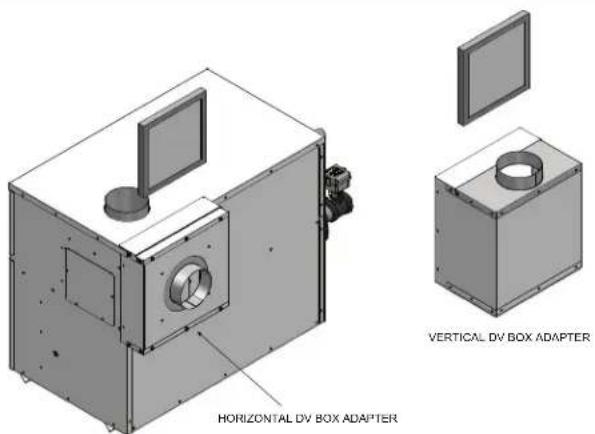
text_image
HORIZONTAL DV BOX ADAPTER VERTICAL DV BOX ADAPTERFigure 2-11_Attaching DV Box Adapter to Unit

natural_image
3D rendering of a mechanical device with a central circular component and mounting bracket (no text or symbols visible)Figure 2-12_Moving Air Filter Assembly & DV Box Adapter
Air inlet piping materials
The air inlet pipe(s) must be sealed. Select air inlet pipe material from the following specified materials.
- PVC, CPVC, or ABS*
- Dryer vent or sealed flexible duct (not recommended for rooftop air inlet)
• Galvanized steel vent pipe with joints and seams sealed as specified below - Type-B double-wall vent with joints and seams sealed as specified below.
* Plastic pipe may require an adapter (not provided) to transition between the air inlet connection on the unit and the plastic air inlet pipe.
WARNING
Use only vent or air intake materials specified in this manual. Follow vent pipe manufacturer's instructions. Failure to do so can result in property damage, personal injury, or death. Mixing of venting materials will void the warranty and certification of this unit.
Sealing Type-B double-wall vent pipe or galvanized vent pipe
Follow the steps below to properly seal Type-B double-wall vent pipe or galvanized vent pipe.
- Seal all joints and seams of the air inlet pipe using either aluminum foil duct tape meeting UL Standard 723 or 181 A-P or a high quality UL Listed silicon sealant such as those manufactured by Dow Corning or General Electric.
- On horizontal runs, do not install vent pipe with seams pointing down. Position vent pipe so that the seams are on the top side of the vent pipe.
- Secure all joints with a minimum of three sheet metal screws or pop rivets. Apply aluminum foil duct tape or silicone sealant to all screws or rivets installed in the vent pipe.
- Ensure that the air inlet pipes are properly supported.
Sealing PVC, CPVC, ABS, dryer vent, and flex duct vent pipe
- Clean the PVC, CPVC, or ABS air inlet pipe using the pipe manufacturer's recommended solvents. Seal the pipe joints using standard commercial pipe cement.
2 Venting
- For PVC, CPVC, ABS, dryer vent, or flex duct air inlet piping, use a silicone sealant to ensure a proper seal at the unit inlet and the air inlet cap.
- For Dryer vent or flex duct, also use a screw-type clamp to attach the inlet vent material to the unit inlet and the air inlet cap. Properly sealing the air inlet pipe ensures that combustion air will be free of contaminates and supplied in proper volume.
- Ensure that the air inlet pipes are properly supported.

Properly seal all joints and seams in the inlet vent piping system. Failure to do so may result in flue gas recirculation, spillage of flue products, and carbon monoxide emissions. Carbon monoxide poisoning can cause severe personal injury or death.
Vertical and sidewall combustion air inlet

To prevent recirculation of flue products into the combustion air inlet, follow all instructions in this section.

Locate and install the combustion air inlet termination correctly. Failure to do so can allow the discharge of flue products to be drawn into the combustion process. This can result in incomplete combustion and potentially hazardous levels of carbon monoxide in the flue products. This will cause operational problems and the spillage of flue products. Spillage of flue products can cause personal injury or death due to carbon monoxide poisoning.
You must locate the combustion air cap and the flue gas outlet on the same rooftop surface (vertical direct vent system) or sidewall surface (horizontal direct vent system) and in the same pressure zone as the vent termination. Follow all clearance requirements listed on this page.
Purchase and assemble the combustion air inlet cap to protect the air inlet from wind and weather.
Alternatively, assemble the combustion air inlet cap for vertical rooftop air inlet from items purchased locally. The air inlet cap consists of two 90° elbows installed to the air inlet pipe (see FIG. 2-13). Install the first 90° elbow on the rooftop at the highest vertical point of the air inlet pipe. Install the second 90° elbow on the horizontal outlet of the first elbow. The outlet of the second 90° elbow will be pointing down. You may use a 90° elbow and a 90° straight elbow to make this assembly. If you use a straight piece of pipe between the two 90° elbows, it should not exceed 6" (51 mm) in length.

natural_image
3D CAD model of a pipe fitting with a circular hole and 6-inch maximum clearance (no text or symbols)Figure 2-13_Vertical Rooftop Air Inlet
For horizontal direct vent termination of combustion air, you must use the termination cap from the appliance manufacturer. The sidewall air inlet cap is available as part of a direct vent kit. See Table 2E, page 26 for Horizontal Direct Vent Kits.
Vertical Combustion Air Inlet Clearances
You must locate the air inlet termination elbow at least 12" (30 cm) above the roof or above normal snow levels.
If the air inlet cap is within a 10-foot (3.05 m) radius of the flue outlet, the point of termination for the combustion air inlet cap must be at least 3 feet (0.91 m) below the point of flue gas termination (vent cap).
Do not install the combustion air inlet cap closer than 10 feet (3.05 m) from an inside corner of an L-shaped structure.
Horizontal combustion air inlet clearances
You must locate the horizontal air inlet termination point at least 12" (30 cm) above grade and above normal snow levels.
If the air inlet cap is within a 10-foot (3.05 m) radius of the flue outlet, the point of termination for the combustion air inlet cap must be at least 3 feet (0.91 m) below the point of flue gas termination (vent cap). Do not install the horizontal combustion air inlet cap above the flue outlet.
Do not install the combustion air inlet cap closer than 10 feet (3.05 m) from an inside corner of an L-shaped structure.
Multiple sidewall direct vent installations
You must locate the horizontal air inlet termination points at least 12" (30 cm) above grade and above normal snow levels. The combustion air inlet caps for multiple appliance installations must maintain the same minimum clearance from the closest flue vent cap as specified in single appliance installations. You may install multiple flue outlet caps side-by-side and multiple combustion air inlet caps side-by-side, but the air inlet must always be at least 3 feet (0.91 m) horizontally and 3 feet (0.91 m) below the closest flue outlet. Do not install combustion air inlet caps above the flue outlets.
Maintain all clearances and installation requirements for multiple appliance installations.
2 Venting (continued)
Figure 2-14A Direct Vent Terminal Clearances

text_image
Inside corner detail G V A D E L B O C V Fixed closed Operable F B B Operable Fixed closed V B A J X H 15 ft M V K Regulator vent outlet In the event no regulator is present, H and I can be disregarded. Legend: V = Vent terminal X = Air supply inlet Area where terminal is not permittedTable 2F Direct Vent Terminal Clearances
| Canadian Installations^1 | US Installations^2 | ||
| A = | Clearance above grade, veranda, porch, deck, or balcony | 12 in (30 cm) 12 in (30 cm) | |
| B = | Clearance to window or door that may be opened | 6 in (15 cm) for appliances ≤ 10,000 Btuh (3 kW), 12 in (30 cm) for appliances > 10,000 Btuh (3 kW) and ≤ 100,000 Btuh (30 kW), 36 in (91 cm) for appliances > 100,000 Btuh (30 kW) | 6 in (15 cm) for appliances ≤ 10,000 Btuh (3 kW), 9 in (23 cm) for appliances > 10,000 Btuh (3 kW) and ≤ 50,000 Btuh (15 kW), 12 in (30 cm) for appliances > 50,000 Btuh (15 kW) |
| C = | Clearance to permanently closed window | * | * |
| D = | Vertical clearance to ventilated soffit located above the terminal within a horizontal distance of 2 ft (61 cm) from the center line of the terminal. | * | * |
| E = Clearance to unventilated soffit | * | * | |
| F = Clearance to outside corner | * | * | |
| G = Clearance to inside corner | * | * | |
| H = | Clearance to each side of center line extended above meter / regulator assembly | 3 ft (91 cm) within a height 15 ft (4.6 m) | * |
| I = | Clearance to service regulator vent outlet | 3 ft (91 cm) | * |
2 Venting
Table 2F Direct Vent Terminal Clearances (continued)
| J = | Clearance to nonmechanical air supply inlet to building or the combustion air inlet to any other appliance | 6 in (15 cm) for appliances ≤ 10,000 Btuh (3kW), 12 in (30 cm) for appliances > 10,000 Btuh (3 kW) and ≤ 100,000 Btuh (30 kW), 36 in (91 cm) for appliances > 100,000 Btuh (30 kW) | 6 in (15 cm) for appliances ≤ 10,000 Btuh (3kW), 9 in (23 cm) for appliances > 10,000 Btuh (3 kW) and ≤ 50,000 Btuh (15 kW), 12 in (30 cm) for appliances > 50,000 Btuh (15 kW) |
| K = | Clearance to a mechanical air supply inlet | 6 ft (1.83 m) | 3 ft (91 cm) above if within 10 ft (3 m) horizontally |
| L = | Clearance above paved sidewalk or paved driveway located on public property | 7 ft (2.13 m)† | 7 ft (2.13 m) for mechanical draft systems (Category I appliances). Vents for Category II and IV appliances cannot be located above public walkways or other areas where condensate or vapor can cause a nuisance or hazard |
| M = | Clearance under veranda, porch, deck, or balcony | 12 in (30 cm)‡ * | |
| * Clearance in accordance with local installation codes and the requirements of the gas supplier.† A vent shall not terminate directly above a sidewalk or paved driveway that is located between two single family dwellings and serves both dwellings.‡ Permitted only if veranda, porch, deck, or balcony is fully open on a minimum of two sides beneath he floor. | |||
| NOTES:1) In accordance with the current CSA B149.1, Natural Gas and Propane Installation Code2) In accordance with the current ANSI Z223.1/NFPA 54, National Fuel Gas Code | |||
Figure 2-14B Other than Direct Vent Terminal Clearances
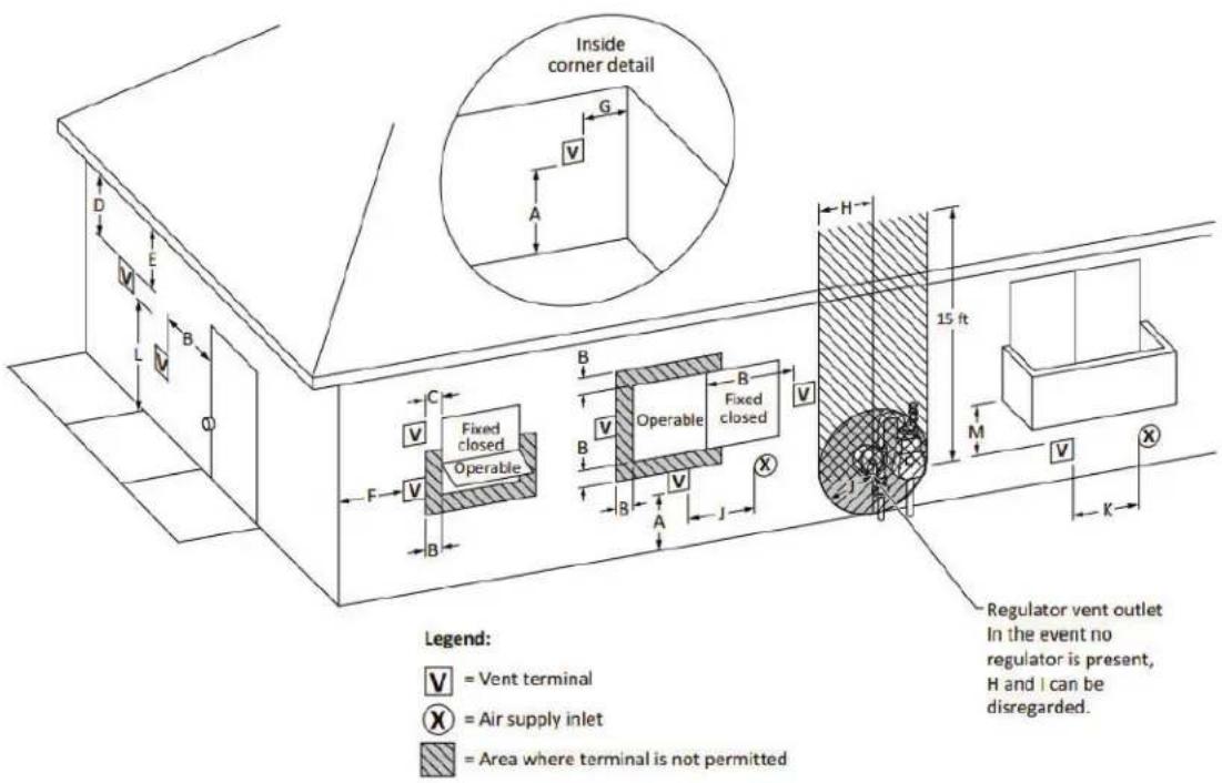
text_image
Inside corner detail G A D E V L B Q C Fixed closed Operable F B B B Operable Fixed closed V H 15 ft M V X K Legend: V = Vent terminal X = Air supply inlet Area where terminal is not permitted Regulator vent outlet In the event no regulator is present, H and I can be disregarded.2 Venting (continued)
Table 2G Other than Direct Vent Terminal Clearances
| Canadian Installations^1 | US Installations^2 | ||
| A = | Clearance above grade, veranda, porch, deck, or balcony | 12 in (30 cm) 12 in (30 cm) | |
| B = | Clearance to window or door that may be opened | 6 in (15 cm) for appliances ≤ 10,000 Btuh (3 kW), 12 in (30 cm) for appliances > 10,000 Btuh (3 kW) and ≤ 100,000 Btuh (30 kW), 36 in (91 cm) for appliances > 100,000 Btuh (30 kW) | 4 ft (1.2 m) below or to side of opening; 1 ft (300 mm) above opening |
| C = | Clearance to permanently closed window | * | * |
| D = | Vertical clearance to ventilated soffit located above the terminal within a horizontal distance of 2 ft (61 cm) from the center line of the terminal. | * | * |
| E = Clearance to unventilated soffit | * | * | |
| F = Clearance to outside corner | * | * | |
| G = Clearance to inside corner | * | * | |
| H = | Clearance to each side of center line extended above meter / regulator assembly | 3 ft (91 cm) within a height 15 ft (4.6 m) | * |
| I = | Clearance to service regulator vent outlet | 3 ft (91 cm) | * |
| J = | Clearance to nonmechanical air supply inlet to building or the combustion air inlet to any other appliance | 6 in (15 cm) for appliances ≤ 10,000 Btuh (3kW), 12 in (30 cm) for appliances > 10,000 Btuh (3 kW) and ≤ 100,000 Btuh (30 kW), 36 in (91 cm) for appliances > 100,000 Btuh (30 kW) | 4 ft (1.2 m) below or to side of opening; 1 ft (300 mm) above Opening |
| K = | Clearance to a mechanical air supply inlet | 6 ft (1.83 m) 3 ft (91 cm) above if within 10 ft (3 m) horizontally | |
| L = | Clearance above paved sidewalk or paved driveway located on public property | 7 ft (2.13 m)† 7 ft (2.13 m) for mechanical draft systems (Category I appliances). Vents for Category II and IV appliances cannot be located above public walkways or other areas where condensate or vapor can cause a nuisance or hazard | |
| M = | Clearance under veranda, porch, deck, or balcony | 12 in (30 cm)‡ * | |
| * Clearance in accordance with local installation codes and the requirements of the gas supplier.† A vent shall not terminate directly above a sidewalk or paved driveway that is located between two single family dwellings and serves both dwellings.‡ Permitted only if veranda, porch, deck, or balcony is fully open on a minimum of two sides beneath he floor.NOTES:1) In accordance with the current CSA B149.1, Natural Gas and Propane Installation Code2) In accordance with the current ANSI Z223.1/NFPA 54, National Fuel Gas Code | |||
2 Venting

Outdoor installation - see page 13.
NOTICE
Before installing a venting system, follow all requirements found in the General Venting section.
Units are self-venting and can be used outdoors when installed with the optional outdoor cap. This cap mounts directly to the top of the unit and covers the flue outlet and combustion air inlet openings. No additional vent piping is required.

Only install outdoor models outdoors and only use the vent cap supplied by the appliance manufacturer. Personal injury or product damage may result if any other cap is used or if an outdoor model is used indoors. Properly install all covers, doors and jacket panels to ensure proper operation and prevent a hazardous condition.
Combustion air supply must be free of contaminants (see Combustion and Ventilation Air, page 9). To prevent recirculation of the flue products into the combustion air inlet, follow all instructions in this section.
Outdoor vent/air inlet location
Keep venting areas free of obstructions. Keep area clean and free of combustible and flammable materials. Maintain a minimum clearance of 3" (76 mm) to combustible surfaces and a minimum of 36" (915 mm) clearance to the air inlet. To avoid a blocked air inlet or blocked flue condition, keep the outdoor cap air inlet, flue outlet and drain slot clear of snow, ice, leaves, debris, etc.
Do not install outdoor models directly on the ground. You must install the outdoor unit on a concrete, brick, block, or other non-combustible pad.
Do not locate unit so that high winds can deflect off of adjacent walls, buildings or shrubbery causing recirculation. Recirculation of flue products may cause operational problems, bad combustion or damage to controls. Locate unit at least 3 feet (0.91 m) from any wall or vertical surface to prevent wind conditions from affecting performance.
Multiple unit outdoor installations require 48" (1.22 m) clearance between each vent cap. Locate outdoor cap at least 48" (1.22m) below and 48" (1.22 m) horizontally from any window, door, walkway or gravity air intake.
Locate unit at least 10 feet (3.05 m) away from any forced air inlet.
Locate unit at least 3 feet (0.91 m) outside any overhang.
Clearances around outdoor installations can change with time. Do not allow the growth of trees, shrubs or other plants to obstruct the proper operation of the outdoor vent system.
Do not install in locations where rain from building runoff drains will spill onto the unit.
Do not install outdoor units on stack frames.
Flue gas condensate can freeze on exterior walls or on the vent cap. Frozen condensate on the vent cap can result in a blocked flue condition. Some discoloration to exterior building or unit surfaces can be expected. Adjacent brick or masonry surfaces should be protected with a rust resistant sheet metal plate.
The outdoor vent cap kit
The optional outdoor vent cap kit is available from the appliance manufacturer. The outdoor cap part numbers are listed by model number. See Table 2H for kit numbers.
Install the outdoor vent cap on the rear of the unit. Complete installation instructions are included with the outdoor vent cap kit.
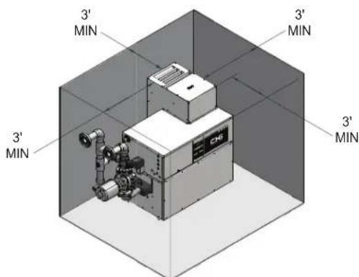
text_image
3' MIN 3' MIN 3' MIN 3'Figure 2-15_Outdoor Vent Cap Installed

| TABLE - 2HOUTDOOR VENT CAP KITS | |
| MODEL OUTDOOR VENT KIT | |
| CXi500 100163840 | |
| CXi650 100163841 | |
| CXi750 100163841 | |
3 Gas connections
Connecting to gas supply
Verify that the appliance is supplied with the type of gas specified on the rating plate. This appliance is configured for operation up to 4,500 feet altitude. Consult factory for installations above 4,500 feet elevation.
Inlet gas pressure: Measured at the inlet pressure tap on the appliance gas manifold. The pressure tap is located upstream of the combination gas valve(s).
See Table 3A for maximum and minimum inlet pressures. Do not exceed the maximum. Minimum inlet pressure is for the purpose of input adjustment.
| TABLE 3AINLET GAS PRESSURE | ||||
| MODEL | NATURAL LP | |||
| Max.w.c. | Min.w.c. | Max.w.c. | Min.w.c. | |
| 500 - 750 14" 4.5" 14" 8.0" | ||||
Manifold pressure: The gas regulator on the unit's combination gas valve is adjustable to supply proper manifold pressure for normal operation. See the Jandy® CXi™ Pool Heater Service Manual for net manifold pressure settings.
If you must adjust regulator pressure, follow the instructions under Gas Manifold Pressure Adjustment in the Jandy® CXi™ Pool Heater Service Manual. Do not increase regulator pressure beyond specified pressure setting.
Gas pressure test
- The appliance must be disconnected from the gas supply piping system during any pressure testing of that system at a test pressure in excess of 1/2 PSIG (3.5 kPa).
- The appliance must be isolated from the gas supply piping system by closing a manual shutoff valve during any pressure testing of the gas supply piping system at test pressures equal to or less than 1/2 PSIG (3.5 kPa).
- The appliance and its gas connection must be leak tested before placing it in operation.
Checking manifold gas pressure
Reference the Jandy® CXi™ Pool Heater Service Manual for information regarding manifold gas pressure.
Gas piping
To safely operate this pool heater, you must properly size the gas supply piping. See Tables 3B through 3D for piping and fitting requirements. Gas pipe size may be larger than pool heater connection.
On Models CXi500, CXi650, and CXi750, the gas connection to the pool heaters are 1 1/4" NPT.
For ease of service, install a union.
Install a manual main gas shutoff valve, outside of the unit gas connection within six feet of the unit in accordance with the requirements of the National Fuel Gas Code, ANSI Z223.1.
You must provide a sediment trap (drip leg) in the inlet of the gas connection to the unit.
NOTICE
It is the installer's responsibility to supply the sediment trap (drip leg).
CAUTION
Do not block access to the electrical cover plate when installing the sediment trap. The sediment trap must be a minimum of 12 inches from the appliance.
The combination gas valves have an integral vent limiting device and do not require venting to atmosphere, outside the building. The unit will not operate properly if the reference hose is removed or a vent to atmosphere is installed.
Optional gas controls may require routing of bleeds and vents to the atmosphere, outside the building when required by local codes.
Gas connection
All gas connections must be made with pipe joint compound resistant to the action of liquefied petroleum (L.P.) and natural gases. All piping must comply with local codes and ordinances. Piping installations must comply with approved standards and practices.
- Make sure gas line is a separate line direct from the meter unless the existing gas line is of sufficient capacity. Verify pipe size with your gas supplier.

text_image
12" MIN USE WRENCH TO HOLD SUPPLY PIPE UNION MANUAL MAIN SHUTOFF VALVE NIPPLE CAPFigure 3-1_Gas Line Connection
NOTICE
If an inline high gas pressure regulator is used, it MUST BE of the lockup type and be located a minimum of 10 feet from the appliance. Failure to do so may result in insufficient gas volume supplied to the appliance.
3 Gas connections
- Use new, properly threaded black iron pipe free from chips. If you use tubing, make sure the ends are cut square, deburred and clean. Make all tubing bends smooth and without deformation. Avoid flexible gas connections. Internal diameter of flexible lines may not provide unit with proper volume of gas.
- Install a manual main gas shutoff valve at the unit's gas inlet, outside of the unit.
- Run pipe or tubing to the unit's gas inlet. If you use tubing, obtain a tube to pipe coupling to connect the tubing to the unit's gas inlet.
- Install a sediment trap in the supply line to the unit's gas inlet (see FIG. 3-1).
- Apply a moderate amount of good quality pipe compound (do not use Teflon tape) to pipe only, leaving two end threads bare.
- Remove seal over gas inlet to unit.
- Connect gas pipe to inlet of unit. Use wrench to support gas manifold on the unit.
- For L.P. gas, consult your L.P. gas supplier for expert installation.
- Ensure that all air is completely bled from the gas line before starting the ignition sequence. Start up without properly bleeding air from the gas line may require multiple reset functions of the ignition control module to achieve proper ignition.

Do not have any open flame in proximity to the gas line when bleeding air from the gas line. Gas may be present.
Gas train and controls

The gas train and controls assembly provided on this unit have been tested under the applicable American National Standard to meet minimum safety and performance criteria such as safe lighting, combustion and safety shutdown operation.
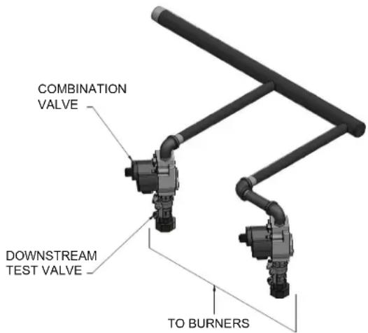
text_image
COMBINATION VALVE DOWNSTREAM TEST VALVE TO BURNERSFigure 3-2 Typical Pool Heater Gas Train Drawing
| TABLE 3BSUGGESTED GAS PIPE SIZE FORSINGLE UNIT INSTALLATIONS | |||||
| MODEL | Distance from Meter (in feet) | ||||
| 0 - 50 | 51 - 100 | 101-200 | 201-300 | 301-500 | |
| CXi500 | 1 1/4" | 1 1/2" | 2" | 2" | 2 1/2" |
| CXi650 | 1 1/2" | 2" | 2" | 2 1/2" | 2 1/2" |
| CXi750 | 1 1/2" | 2" | 2" | 2 1/2" | 3" |
| For each elbow or tee, add equivalent straight pipe to total length from Table 3C. | |||||
| TABLE - 3CFITTINGS TO EQUIVALENT STRAIGHT PIPE | ||||||||
| Diameter Pipe (inches) | 3/4 | 1 1/4 | 1 1/2 | 3 4 5 | ||||
| Equivalent length of Straight Pipe (feet) | 2 | 2 | 3 | 4 | 5 | 10 | 14 | 20 |
Combination gas valves
These units fire in multiple stages of burner input. Each stage of burner operation has a combination gas valve(s) to cycle the gas supply on and off and regulate gas to the burners. Each combination valve consists of a gas regulator and two valve seats to meet the requirements for redundant gas valves. The valve has a gas control knob that must remain in the open position at all times when the unit is in service. The gas control valve has pressure taps located on the inlet and discharge sides of the valve. Manifold pressure is adjusted using the regulator located on the valve. A manifold gas pressure tap for each burner stick is located on the discharge side of the valve.
The manifold pressure is preset at the factory and adjustment is not usually required. If you must adjust regulator pressure, follow the instructions in the Jandy® CXi™ Service Manual.
Venting of combination gas valves
The combination gas valve/regulator used on all units is equipped with an integral vent limiting orifice per ANSI Z21.78. The vent limiter ensures that the volume of gas emitted from the valve in the event of a failed gas diaphragm does not exceed the maximum safe leakage rate allowed by agency requirements.
3 Gas connections (continued)
Combination gas valve/regulators equipped with integral vent limiters are not required to have vent or relief lines piped to the outdoors. The termination of the vent limited opening on the combination gas valve/regulator complies with the safety code requirements of CSD-1, CF-190(a) as shipped from the appliance manufacturer without the installation of additional vent lines.
Checking gas supply pressure
Use the following procedure to check gas supply pressure.
-
Turn the main power switch to the "OFF" position.
-
Turn gas valve knobs to the "OFF" position.
-
Shut off gas supply at the field-installed manual gas cock in the gas piping to the unit. If fuel supply is L.P. gas, shut off gas supply at the tank.
-
Remove the 1/8" hex plug, located on the "inlet" side of the gas valve. You may also use a tapping on the field-installed main manual gas cock or gas piping. Install a fitting in the inlet pressure tapping suitable to connect to a manometer or magnehelic gauge. Range of scale should be 14" w.c. or greater to check inlet pressure.
-
Turn on gas supply at the manual gas cock, turn on L.P. gas at the tank if required.
-
Turn the power switch to the "ON" position.
-
Turn the gas valve knobs to the "ON" position. Set the electronic temperature control or thermostat to call for heat.
-
Observe the gas supply pressure as all burners are firing. Ensure that inlet pressure is within the specified range. See Connecting To Gas Supply, page 33 for minimum and maximum gas supply pressures.
-
If gas pressure is out of range, contact gas utility, gas supplier, qualified installer or service agency to determine necessary steps to provide proper gas pressure to the control.
-
If gas supply pressure is within normal range, turn the power switch to the "OFF" position.
-
Turn gas valve knobs to the "OFF" position.
-
Shut off gas supply at the manual gas cock in the gas piping to the unit. If fuel supply is L.P. gas, shut off gas supply at the tank.
-
Remove the manometer and related fitting from the "inlet" side of the gas valve, replace 1/8" hex plug in gas valve and tighten.
- Turn on gas supply at the manual valve, turn on L.P. gas at the tank if required.
- Turn the power switch to the "ON" position.
- Turn the gas valve knob to the "ON" position.
- Set the electronic temperature control or thermostat to call for heat.
WARNING
After completing any testing on the gas system, leak test all gas connections. Apply a soap/water solution to all gas connections while main burners are operating. Bubbles forming indicate a leak. Repair all leaks at once. Do not operate this unit with a leak in the gas train, valves or related piping.
Check burner performance by cycling the system while you observe burner response. Burners should ignite promptly. Flame pattern should be stable, see Burner Flames in the Jandy® CXi™ Service Manual. Turn system off and allow burners to cool, then cycle burners again to ensure proper ignition and flame characteristics.
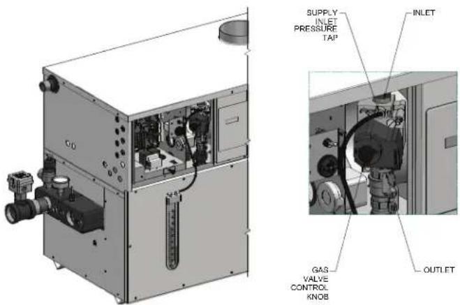
text_image
SUPPLY INLET PRESSURE TAP INLET GAS VALVE CONTROL KNOB OUTLETFigure 3-3_Measuring Gas Supply Pressure at Combination Gas Valve
| TABLE - 3DCapacity of Schedule 40 Metallic Pipe in Cubic Feet of Natural Gas Per Hour (based on .60 specific gravity, 0.30" w.c. pressure drop) | ||||||||||||||
| Pipe Size(Inches) | Length of Pipe in Straight Feet | |||||||||||||
| 10 20 | 30 40 | 50 60 | 70 | 80 90 | 100 125 | 150 175 | 200 | |||||||
| 1/2 | 131 | 90 | 72 | 62 | 55 | N/A | N/A | N/A | N/A | N/A | N/A | N/A | N/A | N/A |
| 3/4 | 273 | 188 | 151 | 129 | 114 | 104 | 95 | 89 | 83 | 79 | 70 | 63 | 58 | N/A |
| 1 | 514 | 353 | 284 | 243 | 215 | 195 | 179 | 167 | 157 | 148 | 131 | 119 | 109 | 102 |
| 1 1/4 | 1,060 | 726 | 583 | 499 | 442 | 400 | 368 | 343 | 322 | 304 | 269 | 244 | 224 | 209 |
| 1 1/2 | 1,580 | 1,090 | 873 | 747 | 662 | 600 | 552 | 514 | 482 | 455 | 403 | 366 | 336 | 313 |
| 2 | 3,050 | 2,090 | 1,680 | 1,440 | 1,280 | 1,160 | 1,060 | 989 | 928 | 877 | 777 | 704 | 648 | 602 |
| 2 1/2 | 4,860 | 3,340 | 2,680 | 2,290 | 2,030 | 1,840 | 1,690 | 1,580 | 1,480 | 1,400 | 1,240 | 1,120 | 1,030 | 960 |
| 3 | 8,580 | 5,900 | 4,740 | 4,050 | 3,590 | 3,260 | 3,000 | 2,790 | 2,610 | 2,470 | 2,190 | 1,980 | 1,820 | 1,700 |
| 4 | 17,500 | 12,000 | 9,660 | 8,270 | 7,330 | 6,640 | 6,110 | 5,680 | 5,330 | 5,040 | 4,460 | 4,050 | 3,720 | 3,460 |
4 Water connections
Install piping from the filter system to the pool heater as shown in the pool heater piping diagrams. See Figures 4-3 - 4-7. Minimum pipe diameter to and from the installed pool heater to the filter system piping is 2". The piping from the filter system to the pool heater may be PVC, CPVC or Copper Pipe. The piping from the pool heater back to the filter system will carry water with temperatures in excess of 110°F and must be CPVC or Copper Pipe. The temperature of the heated water from the pool heater will be substantially cooled as it is mixed back into the pool water from the filter system and returned to the pool. The mix of heated water and pool water from the filtration system should only be slightly warmer than the pool water before the connections from the pool heater.

text_image
2" NPT WATER OUTLET 2" NPT WATER INLETFigure 4-1_Water Connections
| TABLE - 4APipe Sizing Chart | |
| 500 - 750 ModelsNumber of units | Common Pipe Size(Min.) |
| 1 | 2" |
| 2 | 3 |
| 3 | 4 |
| 4 | 4 |
| 5 | 6 |
| 6 | 6 |
Circulating pump
- This pool heater is factory supplied with a properly sized pump that circulates water between the pool heater and system.
- The pump is sized to pool heater input and water hardness. See Water Chemistry on page 47.
- Lubricate the pump to the manufacturer's recommendations. Pump damage due to inadequate lubrication is non-warrantable. Use SAE 30 non-detergent oil or lubricant specified by the pump manufacturer.
- Standard pool heaters are furnished with the following circulating pump mounted in the factory supplied pool loop.
CXi500, CXi650, and CXi750 Models 1/4 HP, 120 VAC, 5.8 Amp
This pump is sized based on installation of a single pool heater in close proximity with the system. The piping can be changed to a sub-loop. Check pump for correct pump rotation.
The standard pump selection is based on the following pipe and fittings from the pool heater to the system:
4 Water connections (continued)
The water connections / sub-loop shall not be smaller than what is called out in Table 4A. The total length of the sub-loop shall not total more than 45 equivalent feet of linear pipe.
NOTICE
For every elbow and tee in excess of those shown above, deduct 5 feet from the maximum allowable straight pipe in the pool heater to the system circulating loop.
Minimum Pump Performance
Pump performance is based on providing adequate flow to prevent scale accumulation in the heat exchanger. See Water Chemistry on page 47.
| TABLE-4BMinimum Pump Performance | ||
| Models GPM | Ft.Hd. | |
| 500 - 750 55 10 | ||
Heat exchanger
A Cupro-Nickel heat exchanger is standard on 500 - 750 models. On all models, header inspection plugs can be removed for field inspection and cleaning of copper tubes. The entire heat exchanger may be easily removed from the pool heater.
WARNING
Should overheating occur or the gas supply fail to shut off, do not turn off or disconnect the electrical supply to the pump. Instead, shut off the gas supply at a location external to the pool heater.
Initial set-up of maximum water flow
On initial start-up of the Jandy® CXi™ pool heater, the maximum water flow to the heat exchanger must be checked and manually limited with a valve or bypass before normal operation begins.
Table 4C_Pressure Loss Table
CAUTION
An appliance allowed to operate at return temperatures below the specified minimum setting may experience problems with the operating controls, safety switches, obstruction of the flue gas passages on the heat exchanger, incomplete combustion and possible flue gas spillage. Sustained operation at lower than specified water temperatures (140°F) may cause hazardous conditions that may result in personal injury or non-warrantable damage to the appliance.
Auxiliary Mixed Water Limit Control
Pool return and pool supply (mixed water limit) sensors (reference FIG. 4-3, page 38):
Ensure pool return and pool supply (mixed water limit) sensors are both installed in the system piping. The return sensor should be installed in the upstream of the feed water to the pool heater. The supply sensor limits the temperature of the water going back to the pool (factory adjusted to ≤110^ ). The supply sensor may be installed in the filtration system piping, be sure to keep it at least three (3) feet downstream from the point where the heated water from the pool heater is being added to the filtration system.
Note: In order to accurately sense water temperatures, both sensors need to be in the actual water flow.
Installation of return and supply sensors:
Both pool sensors are immersion type sensors with 1/4" NPT threads and may be installed directly into the system piping by drilling 7/16" pilot holes and tapping them with a 1/4" NPT tapered tap. Apply a small amount of high quality RTV silicone sealant to the threads to prevent leaks and install the sensors into the threaded openings in the PVC pipe. Over-tightening can damage the parts and/or strip the threads cut into the plastic pipe.
Sensor connections:
The sensors are connected to the pool heater from the factory. The return sensor is a two-wire sensor and the supply sensor is a four-wire sensor. Disconnects are provided for each sensor. If disconnected to facilitate installation, re-connection is necessary after installation. If sensors must be located further than allowed by the cables provided, any extension cabling must be of equivalent type and wire gauge (see Table 5B on page 43 of this manual for recommended gauges). IMPORTANT: If the unit is to be installed outdoors, weatherproof connections must be provided over all sensor connections.
| CONFIGURATION | PIPE SIZE PRESSURE LOSS (PSI) HEAD LOSS (FT) | WHERE USED | |
| VERTICAL 2" 1. | 67 3.9 CXi500, CXi650, CXi750 | ||
| HORIZONTAL 2" | 1.88 4.4 CXi500, CXi650, CXi750 |
4 Water connections
Figure 4-3_Heater Within 15 feet of Pool Piping

text_image
AUTOMATIC BYPASS VALVE POOL RETURN SENSOR * SECONDARY LOCATION * NOTE: IF THE RETURN SYSTEM SENSOR IS LOCATED IN THE SECONDARY LOCATION SHOWN ON THE PIPING DIAGRAM, THE UNIT PUMP MUST RUN CONTINUOUSLY TO ENSURE THE WATER FLOW PAST THE SENSOR IS MAINTAINED. RECOMMENDED ISOLATION VALVE COPPER OR CPVC (SEE TABLE) FROM POOL 110° LIMIT 3' MIN POOL RETURN SENSOR PRIMARY LOCATION BALL VALVE TO POOL REQUIRED POOL SUPPLY SENSOR LOCATION 2000524423 00 MODEL NO CONNECTION SIZE C X I 5 0 0 - 7 5 0 2" MINFigure 4-4_Heater Beyond 15 feet of Pool Piping

text_image
AUTOMATIC BYPASS VALVE POOL RETURN SENSOR * SECONDARY LOCATION RECOMMENDED ISOLATION VALVE COPPER OR CPVC (SEE TABLE) SUBLOOP FROM POOL 20' MAX 110° LIMIT 3' MIN TO POOL REQUIRED POOL SUPPLY SENSOR LOCATION BALL VALVE 12" MAX OR 4X PIPE DIAMETERS POOL RETURN SENSOR PRIMARY LOCATION LOCATED IN THE SECONDARY LOCATION SHOWN ON THE PIPING DIAGRAM, THE UNIT PUMP MUST RUN CONTINUOUSLY TO ENSURE THE WATER FLOW PAST THE SENSOR IS MAINTAINED.| MODEL NO | CONNECTION SIZE | SUBLOOP SIZE | SUBLOOP GPM |
| CXI 500-750 | 2" MIN | 2-1/2" MIN | 100 GPM MIN |

System flow should always remain higher than the required flow for the pool heater(s) when the pool heater(s) is in operation to prevent short cycling and high limit issues.
Please note that these illustrations are meant to show system piping concept only, the installer is responsible for all equipment and detailing required by local codes.
4 Water connections (continued)
Figure 4-5_Cascaded heaters Within 15 feet of Perpendicular Pool Piping
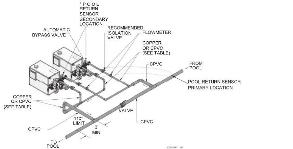
text_image
A UTMOMATIC BYPASS VALVE * POOL RETURN SENSOR SECONDARY LOCATION RECOMMENDED ISOLATION VALVE FLOWMETER COPPER OR CPVC (SEE TABLE) FROM POOL POOL RETURN SENSOR PRIMARY LOCATION COPPER OR CPVC (SEE TABLE) 110" LIMIT CPVC 3' MIN TO POOL VALVE CPVC 200024431 00| MODEL NO | CONNECTION SIZE |
| CXI 500-750 | 2" MIN |
* NOTE: IF THE RETURN SYSTEM SENSOR IS LOCATED IN THE SECONDARY LOCATION SHOWN ON THE PIPING DIAGRAM, THE UNIT PUMP MUST RUN CONTINUOUSLY TO ENSURE THE WATER FLOW PAST THE SENSOR IS MAINTAINED.
Figure 4-6_Cascaded Heaters Beyond 15 feet of Pool Piping

text_image
POOL RETURN SENSOR PRIMARY LOCATION FROM POOL CPVC 3' MIN 110° LIMIT TO POOL *POOL RETURN SENSOR SECONDARY LOCATION FLOWMETER RECOMMENDED ISOLATION VALVE COPPER OR CPVC (SEE TABLE) AUTOMATIC BYPASS VALVE2000524403 08
| MODEL NO | CONNECTION SIZE |
| C X I 5 0 0 - 7 | 5 0 |
2 "M I N
* NOTE: IF THE RETURN SYSTEM SENSOR IS LOCATED IN THE SECONDARY LOCATION SHOWN ON THE PIPING DIAGRAM, THE UNIT PUMP MUST RUN CONTINUOUSLY TO ENSURE THE WATER FLOW PAST THE SENSOR IS MAINTAINED.
NOTICE
System flow should always remain higher than the required flow for the pool heater(s) when the pool heater(s) is in operation to prevent short cycling and high limit issues.
NOTICE
Please note that these illustrations are meant to show system piping concept only, the installer is responsible for all equipment and detailing required by local codes.
4 Water connections
Figure 4-7_Multi-stack frame - Cascaded heaters beyond 15 feet of pool piping
| MODEL NO | CONNECTION SIZE | ||||||
| C | X | I | 5 | 0 | 0 - 7 | 5 | 0 |
2 "M I N

text_image
POOL RETURN SENSOR LOCATION FROM POOL CPVC 3' MIN CPVC FROM PRIMARY LOCATION POOL SUPPLY SENSOR TO POOL 110° LIMIT LEADER MEMBER COPPER OR CPVC (SEE TABLE) FLOWMETER AUTOMATIC BYPASS VALVE RECOMMENDED ISOLATION VALVE2000524470 00
| TABLE 4APIPE SIZING CHART | |
| NUMBER OF UNITS | COMMON PIPE SIZE (MIN) |
| MODELS 500-750 | |
| 1 | 2 |
| 2 | 3 |
| 3 3-1/2" | |
| 4 | 4 |
| 5 | 5 |
| 6 | 5 |

System flow should always remain higher than the required flow for the pool heater(s) when the pool heater(s) is in operation to prevent short cycling and high limit issues.

Please note that these illustrations are meant to show system piping concept only, the installer is responsible for all equipment and detailing required by local codes.
4 Water connections (continued)
Pumped Automatic Bypass
This is a high efficiency pool heater which requires a special pumped bypass for proper operation. The bypass assembly supplied with the pool heater includes a pump and a 3-way mixing valve. All piping to connect the filter system to the pool heater is made directly to the bypass piping on the pool heater.
Outdoor operation: 3-way valve cover
If the pool heater is to be installed outdoors, the 3-way valve must be protected from the elements. A cover for the 3-way valve is included with the outdoor vent kits for all models (see Table 2H on page 32).
Automatic bypass valve cover installation:
The pump supplied on the pool heater bypass has a sealed motor suitable for outdoor installations. When installing the 3-way automatic bypass valve outdoors, an outdoor valve cover is required. An outdoor valve cover is supplied with an optional outdoor vent kit (see Table-2D, page 24 of this manual).
To install the outdoor valve cover, follow the steps below:
- Turn off power to the unit.
- Remove the plastic actuator cover from the 3-way automatic bypass valve by loosening the screw above the conduit fitting (FIG. 4-9).
- Grasp the cover on the screw side and lift the cover up and away from the valve.
-
Disconnect the wires at the terminal block (if connected).
-
Unscrew the plastic conduit cap from the conduit fitting (FIG. 4-9) and pull the plastic conduit hose and wires from the valve.
-
Feed the plastic conduit hose through the opening of the valve cover end cap (100152050) (see FIG. 4-9) and slide the end cap approximately one foot up the conduit.
-
Reconnect the wires to the 3-way valve circuit board as shown in FIG. 4-8.
-
Feed the conduit hose into the conduit fitting and reinstall the conduit cap.
Note: If the wing nut underneath the valve actuator body is loose, retighten.
-
Reinstall the plastic actuator cover and secure with the screw loosened in Step 2.
-
Place the valve cover (100152048) over the 3-way automatic bypass valve. Install the end caps (100152049 and 100152050) using the four screws provided in the kit (100134916) as shown in FIG. 4-9.
-
Turn the power on to the unit and resume operation.
Note: The actuator handle is not used when the outdoor cover is installed. The handle is attached to the underside of the actuator for storage.
Figure 4-8_3 Way Valve Connection Diagram

flowchart
graph TD
    A["DIF SWITCHES"] --> B["Floating Actuator"]
    B --> C["CW"]
    B --> D["CWU"]
    B --> E["COM"]
    C --> F["BLUE TO TERMINAL #7"]
    D --> G["RED TO TERMINAL #5"]
    E --> H["BLACK TO TERMINAL #8"]
    I["DIR +200056239 CC"] --> A
Figure 4-9_3 Way Valve Cover
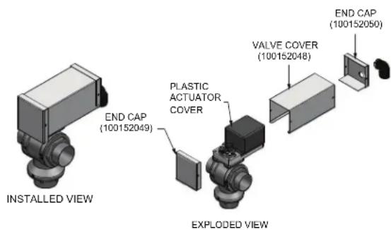
text_image
INSTALLED VIEW END CAP (100152049) PLASTIC ACTUATOR COVER EXPLODED VIEW VALVE COVER (100152048) END CAP (100152050)Manual operation of the 3-way automatic bypass valve actuator
To manually operate the 3-way automatic bypass valve actuator:
- Power must be removed from the unit.
- Once power is removed, the de-clutch button located on the side of the valve actuator body can be pressed.

Failure to remove power from the actuator prior to attempting to manually operate the valve can result in irreparable damage to the actuator mechanism.
4 Water connections
Relief valve
This pool heater is supplied with a relief valve(s) sized in accordance with ASME Boiler and Pressure Vessel Code, Section IV. The relief valve(s) is installed in the vertical position and mounted in the hot water outlet. Place no other valve between the relief valve and the pool heater. To prevent water damage, pipe the discharge from the relief valve to a suitable floor drain for disposal when relief occurs. Do not install any reducing couplings or other restrictions in the discharge line. The discharge line will allow complete drainage of the valve and line. Manually operate the relief valves at least once a year.

Avoid contact with hot discharge water.
Automatic chlorinator and chemical feeders
All chemicals must be diluted into the pool water being circulated through the pool heater. Any concentration of chlorine in the pool heater can cause damage to the pool heater.
Do not place chlorine tablets or bromine sticks in the skimmer. High chemical concentrations will result when the pump is not running.
Chlorinator must feed downstream of the pool heater and have an anti-siphoning device to prevent chemical back-up in the pool heater when the pump is shut off.

High chemical concentrations from improperly adjusted feeders and Chlorinator can cause rapid corrosion to the heat exchanger. This damage is non-warrantable.
Water flow switch
A water flow switch is standard equipment. The wiring connection installs the flow switch in the 24 VAC safety circuit to prove water flow before main burner ignition. The standard flow switch is installed in the outlet side of the piping loop when shipped from the factory. These pool heaters require a sufficient flow of 26 GPM to make the flow switch and start burner operation.
Ensure that the pump installed on the pool heater will supply adequate flow to make the flow switch contacts and operate the pool heater. A water flow switch meets most code requirements for a low-water cut off device on appliances requiring forced circulation for operation.
Pump purge delay
Pump purge (pre-running) delay:
The controller provides a pump purge or pre-running feature. This feature is used whenever the pump has been off for extended periods of time to conserve energy, causing air to become entrapped in the pool system piping. The pump purge/pre-running feature delays pool heater operation until the pump has been on for a sufficient amount of time to remove air from the piping. Both the inactivity time and pump purging/pre-running time are adjustable.
PH-Pump Off:
Inactivity timer is adjustable from 0 to 99 hours. Selection of time between 4 to 8 hours is recommended.
PH-Pump Purge:
Purge or pre-running timer is adjustable from 0 to 60 minutes. Selection of a time between 10 to 30 minutes is recommended.
Note: To override the purge/pre-running feature, press the PREV and NEXT buttons. To disable the feature, the purge/pre-running timer should be set to zero.
5 Electrical connections General information

ELECTRICAL SHOCK HAZARD - For your safety, turn off electrical power supply before making any electrical connections to avoid possible electric shock hazard. Failure to do so can cause severe personal injury or death.
A 120 VAC, 15 Amp, 1 ph, 60 Hz circuit is required for operation of the appliance controls.
The appliance, when installed, must be electrically grounded and bonded in accordance with the requirements of the authority having jurisdiction or in the absence of such requirements, with the latest edition of the National Electrical Code ANSI/NFPA No. 70. When the unit is installed in Canada, it must conform to the CAE C22.1, Canadian Electrical Code, Part I and/or local Electrical Codes. Multiple units connected in a Cascade must be grounded to the same ground connection.
- All wiring between the appliance and field installed devices shall be made with type T wire [63°F (35°C) rise].
- All line voltage wire exterior to the appliance must be enclosed in approved conduit or approved metal clad cable.
- The circulating pump must run continuously when the appliance is being fired.
- To avoid serious damage, DO NOT energize the appliance until the system is full of water. Ensure that all air is removed from the heat exchanger and piping before beginning initial operation. Serious damage may result if the appliance is operated without proper flow.
- Provide the appliance with proper overload protection.

DO NOT block access to the electrical cover plate when installing electrical conduit.
3-way automatic bypass valve wiring
If the piping loop was disassembled for shipping or needs to be fitted with an outdoor enclosure, connection or disconnection of the 3-way automatic bypass valve will be required. Wiring connections should be made to the appropriately numbered terminals on the 3-way automatic bypass valve as follows:
| TABLE-5A3-Way Automatic Bypass Valve Wiring | ||
| Color | FIELD FACTORY | |
| 3-Way Valve Low | Voltage Board | |
| Blue | COM | Terminal #7 |
| Black | CW | Terminal #6 |
| Red | CCW | Terminal #5 |
Note: Orientation of the valve connections may vary from what is shown. Care should be taken to ensure wires are connected to the appropriate terminals, see FIG. 4-8 on page 41 of this manual.

Power must be removed and the clutch button must be depressed before attempting to manually operate the valve, or damage to the 3-way valve may occur.
| TABLE-5BRemote Wire Connection | |
| Wire Gauge | Maximum Allowable Length |
| 12 GA 100 ft. | |
| 14 GA 75 ft. | |
| 16 GA 50 ft. | |
| 18 GA 30 ft. | |
Figure 5-1_Control Panel Component Location
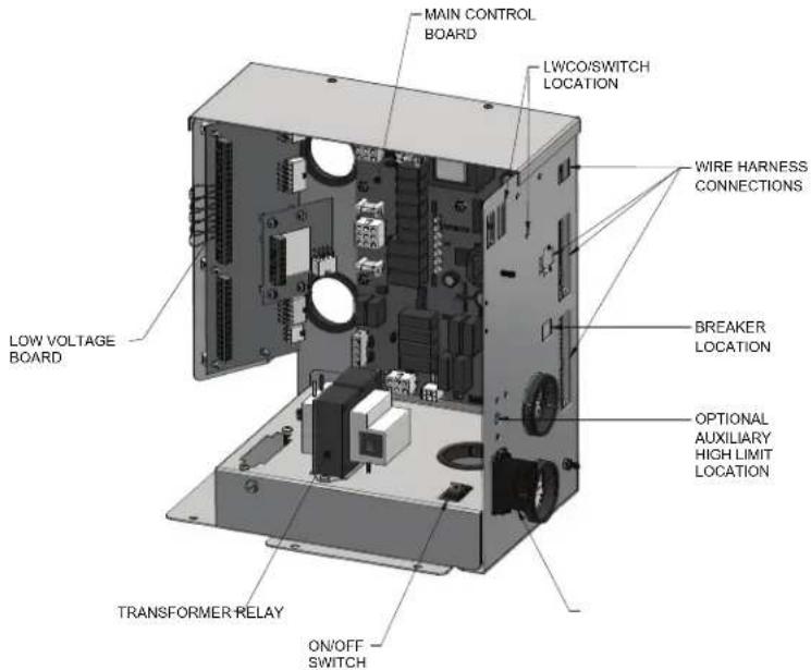
text_image
MAIN CONTROL BOARD LWCO/SWITCH LOCATION WIRE HARNESS CONNECTIONS BREAKER LOCATION OPTIONAL AUXILIARY HIGH LIMIT LOCATION LOW VOLTAGE BOARD TRANSFORMER RELAY ON/OFF SWITCH5 Electrical connections
Pool heater operating control module
The operating control for the appliance is the CXi ^™ control module. It is located on the inside of the control panel, behind the front access door. Access to adjust the temperature set point and other user adjustable points is made through the Operator Interface located on the front access door.
The exact temperature set point is based on the system's requirements. Set the control set point(s) to the desired operating water temperature.
The maximum temperature set point that can be programmed into the control module from the Operator Interface on a pool heater is 105^ F ( 40.5^ C). The manual reset high limit control for a pool heater is adjustable up to a fixed maximum setting of 200^ F ( 93^ C).
| TABLE - 5CAMP DRAW DATA | ||||
| Model | Controls | Blower | Pump FLA* | Approximate Total Amps @ 120 VAC |
| CXi500 3 | 6 2.7 5.8 1 | 2.1 | ||
| CXi650 5 | 4 3.4 5.8 1 | 4.6 | ||
| CXi750 5 | 4 3.4 5.8 1 | 4.6 | ||
| *With standard factory supplied pump. | ||||

ELECTRICAL SHOCK HAZARD – For your safety, turn off electrical power supply before making any electrical connections to avoid possible electric shock hazard. Failure to do so can cause severe personal injury or death.
NOTICE
Wiring must be N.E.C. Class 1.
If original wiring as supplied with the pool heater must be replaced, use only type 105^ C wire or equivalent.
Pool heater must be electrically grounded as required by National Electrical Code ANSI/NFPA 70 – latest edition.

Label all wires prior to disconnection when servicing controls. Wiring errors can cause improper and dangerous operation.
Verify proper operation after servicing.
Installation must comply with:
- National Electrical Code and any other national, state, provincial, local codes, or regulations.
Line voltage connections
- Connect 120 VAC power wiring to the line voltage terminal strip in the junction box, as shown in FIG. 5-2.
- Provide and installafused disconnectorserviceswitch (15AMPrecommended) as required by the code (see FIG. 5-2).
- To activate the unit, wire as shown in FIG. 5-2. If the motor is larger than 1 HP, you must install a contactor.
- When connecting power to units which are to be cascaded, each unit must be connected to the same ground connection.
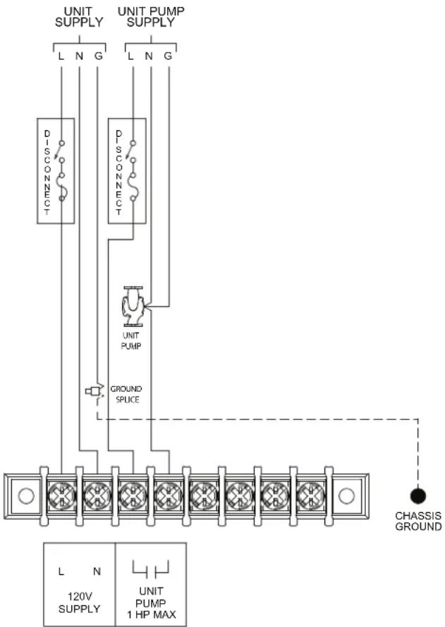
text_image
UNIT SUPPLY UNIT PUMP SUPPLY L N G L N G DISCONNECT P SCONNECT UNIT PUMP GROUND SPLICE CHASSIS GROUND L N 120V SUPPLY UNIT PUMP 1 HP MAXFigure 5-2_Line Voltage Field Wiring Connections
5 Electrical connections (continued)
Low voltage connections
- Route all low voltage wires through the knockouts on the left side of the heater, as shown in FIG. 5-3.
- Connect low voltage wiring to the low voltage connection board as shown in FIG. 5-5 on page 46 of this manual and the heater wiring diagram.
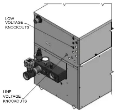
text_image
LOW VOLTAGE KNOCKOUTS LINE VOLTAGE KNOCKOUTSFigure 5-3_Routing Field Wiring
EMS or remote thermostat connection
An EMS, remote thermostat or other remote temperature control may be connected to the pool heater (see FIG. 5-4). Follow the manufacturer's instructions supplied with the remote temperature control for proper installation and adjustment. Connection of a set of dry switching contacts or a remote on/off thermostat to the low voltage connection board will allow the unit to be switched on and off by making or breaking a 24 VAC control circuit. Remove the factory jumper between the Staging S1 terminals on the low voltage connection board and connect the remote temperature control in its place, see FIG. 5-5 on page 46. Terminals S2, S3, and S4 are not used.
Ensure that all wiring used to connect the switching contacts of the remote temperature controller to the connection board are a minimum of 18 gauge and have a maximum installed length of 300 feet (91.4m). Set the CXi ^™ control to a set point temperature slightly higher than the setting of the remote temperature control. This will ensure that the remote temperature controller functions as the operating control for the heater.
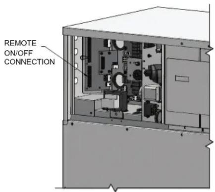
text_image
REMOTE ON/OFF CONNECTIONFigure 5-4_Remote ON/OFF Wire Connection
Louver relay
When the heater is to control combustion air louvers, a field provided 24VAC louver relay must be installed. Connect the Louver Relay Coil terminals to the louver relay coil.
Louver proving switch
The operation of a louver proving switch needs to be verified before the pool heater fires. Remove the jumper wire from these terminals and connect them to the normally open contacts on its proving switch (FIG. 5-5).
Pool return sensor - 2-wire
The pool return sensor should be installed into the return of the primary loop, making sure it is immersed in the water flow. The CXi™ control regulates the pool heater firing rate to maintain the system return temperature to the desired set point for the pool.
Pool supply/limit sensor - 4-wire
The pool supply/limit sensor should be installed into the supply of the primary loop, making sure it is immersed in the water flow. The CXi™ control limits the pool heater firing rate to maintain the system supply temperature. Factory default for the limit temperature is 110°F (43°C).
Runtime contacts
The CXi™ control closes a set of dry contacts whenever the burner is running. This is typically used by Building Management Systems to verify that the pool heater is responding to a call for heat.
3-way valve out
An electric 3-way mixing valve is used to maintain 130^ ( 55^ C) temperature to the heater. Connect the Open output to the Open terminal on the 3-way valve. Connect the Close output to the Close terminal on the valve and the COM output to the 24VAC terminal on the valve. Reference the wiring diagram on page 41 of this manual.
0 - 10V rate out
A 0 - 10VDC signal is available to allow a Building Management System (BMS) to monitor the firing rate of the heater. Make sure the (-) terminal is connected to the (-) or common terminal of the external control, and the (+) terminal is connected to the (+) or Vdc terminal of the external control.
Building Management System (BMS)
- An external control may be connected to control either the firing rate or the set point of the pool heater. Connect the 0 - 10 VDC terminals to the 0 - 10 VDC output of the external control. The CXi™ control can be programmed to use the enable output of the BMS, or use the voltage signal to enable the heater. A BMS or a remote thermostat can be connected to the S1 terminals to enable or disable the unit in place of the factory provided jumper wire.
- Make sure the ground terminal is connected to the ground output terminal of the external control, and the 0 - 10 V BMS IN terminal is connected to the 0 - 10 VDC terminal of the external control.
5 Electrical connections
Alarm contacts
The CXi™ control closes another set of contacts whenever the heater is locked out or the power is turned off. This can be used to turn on an alarm, or signal a Building Management System that the pool heater is down.
Wiring of the cascade
When wiring the heaters for Cascade operation, select one heater as the Leader. The remaining heaters will be designated as Members. See page 50, Configuration of the Cascade for a detailed explanation of this procedure.
The return sensor of the Leader heater should be placed in the main system piping loop, upstream of the water being supplied to all the heaters (see FIG.'s 4-5, 4-6, and 4-7). The return sensors on the remaining Member heaters may also be placed in the same location as the Leader or they can be placed in each Member's PVC piping loop in the Alternate sensor location, using the tapped sensor hole (FIG. 4-3). Should the Leader heater ever need to be replaced with one of the Member heaters in the Cascade, that Member's sensor should be relocated to the previous lead heater's supply sensor location for optimum operation of the cascaded units.
The supply/limit sensors of all cascaded heaters MUST be placed downstream, in the main system piping loop in the blended water, going out to the pool (FIG.'s 4-5, 4-6, and 4-7). The supply/limit sensor also serves as a high temperature limit for pool supply water and failure to locate all sensors in the blended water going out to the pool could result in higher temperature water than desired being discharged to the pool.
If an external thermostat or BMS is being used to enable or disable the cascaded heaters, the external thermostat or BMS should be connected to the Leader heater's S1 input, located on the low voltage terminal board (see FIG. 5-5). Jumpers on all Member heaters should be left in place.
Communication between the Leader and the Member heaters is accomplished by using shielded, 2-wire twisted pair communication cable. Connect one of the twisted pair wires to terminal A on each of the low voltage connection boards, and the other wire of the twisted pair to terminal B on each of the low voltage connection boards. Connect the shield wire to the shield ground terminal on all of the heaters. If more than two heaters are on the Cascade, daisy chain the wiring from the Cascade terminals on the second heater to the Cascade terminals on the third heater, then from the third to the forth, and so on. The connections can be made in any order, regardless of the addresses of the heaters. Try to keep each cable as short as possible.
Figure 5-5_Low Voltage Field Wiring Connections
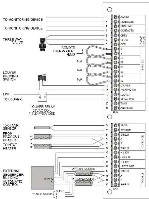
text_image
TO MONITORING DEVICE TO MONITORING DEVICE THREE WAY VALVE REMOTE THERMOSTAT /EMS N/A N/A N/A LOUVER PROVING SWITCH LINE TO LOUVER LOUVER RELAY 24VAC COIL FIELD PROVIDED 1 2 3 4 5 6 7 8 9 10 11 12 13 14 15 16 17 18 19 20 21 CN3 ALARM CONTACTS RUN-TIME CONTACTS OPEN CLOSE COM S1 S1 S2 S2 S3 S3 S4 S4 LOUVER PROVING SW LOUVER RELAY COIL TANK AQUASTAT TANK SENSOR SHIELD CASCADE A B S M S HIELD +0-10V -RMS IN +0-10V RATE OUT SHIELD A B MOTOR B SN 3-WAY VALVE STACHING CN2 10K-TANK SENSOR FROM PREVIOUS HEATER TO NEXT HEATER A U A U A U A U EXTERNAL SEQUENCER/ BUILDING AUTOMATIC CONTROL SHIELD A D TO NEXT BOILER SHIELD A B
text_image
POOL SAFETY SUPPLY 10K/20K POOL/BOILER 10K BK G R W CN2 20K 10K POOL SUPPLY SENSOR 10K POOL RETURN SENSOR NOT USED IMG011586 Startup
Pre-start checklist
Before attempting to start the pool heater verify that the following items have been checked:
- Verify proper location and installation of the pool heater.
- Check gas piping and ensure the gas line is purged of all air.
- Ensure that the pool is properly filled.
- DO NOT operate pool heater if improperly filled.
- Check to ensure that all water connections are tight.
- Relief valve has been piped to a suitable floor drain.
- Combustion air openings are not obstructed in any way.
- Ensure all air is purged from the water piping.
Starting the filter system
Verify proper installation of the pool heater temperature controls and the installation of the 110^ F auxiliary limit and pool supply sensor in the mixed discharge water from the filter piping to the pool. Clean the filter. Start the filter pump. Be sure all air is out of all the lines including the pressure connection. Ensure that the pool heater is not “air bound” by manually opening the temperature and pressure relief valve. Leave the valve open until a steady flow of water is observed at the discharge from the valve. Close the valve and complete filling the system.
Note: Backwash the filter when the G.P.M. filtration rates are too low to meet local codes or state code. A high temperature rise across the pool heater is also an indication of low flow in the filter system. Sustained low flow to the pool heater will result in cycling of the heater on the limit controls and possible opening of the relief valve.
Check for gas leaks

Before starting the unit, and during initial operation, smell near the floor and around the unit for gas odorant or any unusual odor. Remove the front access panel and smell the interior of the pool heater enclosure. Do not proceed with startup if there is any indication of a gas leak. Use an approved leak detection solution. Repair any leaks at once.

The venting system must be installed so that it will prevent flue gas spillage and carbon monoxide emissions, which will result in severe personal injury or death.
Check/control water chemistry

Salt levels above 5000 ppm can cause corrosion damage to heat exchangers.
Factors which affect pool water and, more importantly, the efficiency of your new pool heater are:
- Proper Filtration
-
Proper Circulation
-
Disinfection and Oxidation
- pH Control and Total Alkalinity
- Algae Control
- Water Balance
The water chemistry of your pool changes daily due to natural evaporation of the water and the addition of chemicals. Chemicals are used to sanitize and control algae growth in the pool. Their addition must be carefully monitored. The accumulation of minerals or scale in the pool heater due to a chemical imbalance will cause a non-warrantable failure of the heat exchanger and its components. pH is an important factor in maintaining proper balance in your pool water. pH is the measurement of the acidity or alkalinity of water. The following chart shows the recommended pH range and what can happen when the pH increases or decreases from the ideal of 7.2 to 7.8.
Figure 6-1_pH Scale
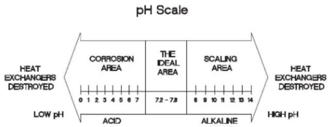
text_image
pH Scale HEAT EXCHANGERS DESTROYED LOW pH CORROSION AREA THE IDEAL AREA SCALING AREA 0 1 2 3 4 5 6 7 7.2 - 7.8 8 9 10 11 12 13 14 ACID ALKALINE HEAT EXCHANGERS DESTROYED HIGH pHIf the pH becomes too high, it lowers the ability of chlorine to destroy bacteria and algae, water can become cloudy, filter elements may become blocked, and scale formation will occur in the pool and heat exchanger. If the pH becomes too low the water becomes acidic. You can have eye burn and skin irritation, etching of the plaster, corrosion of metal fixtures and the resulting stains on the plaster, degradation of sand and gravel filters and corrosion of the copper tubes in the heat exchanger.
Damage to the pool heater, including the pumped bypass, due to improper chemical water balance is non-warrantable. Proper chemical water balance, as indicated by use of the calcium saturation and Ryznar indexes, is required to maintain warranty status of the pool heater and its components. These indexes are designed to help prevent scaling and corrosive damage to the pool and all associated equipment. We recommend the use of a commercial or professional grade test kit to maintain chemical water balance. See your local pool professional for assistance.
Freeze protection
Installations are not recommended in areas where the pool heater will be operated in the winter months and the danger of freezing exists. Proper freeze protection must be provided for outdoor installations; pool heaters installed in unheated equipment rooms or where temperatures may drop to the freezing point or lower.
6 Startup
If freeze protection is not provided for the system, a low ambient temperature alarm is recommended for the equipment room. Damage to the pool heater by freezing is non-warrantable.
- Pump Operation - MOST IMPORTANT - This pool heater is designed for continuous operation of the filter system pump when the burners are firing. If the system pump does not run continuously, an interlock mechanism should be provided to disable when/if the system pump turns off. The constant flow of warm pool water can help prevent freezing.
- Anytime the temperature measured at the sensor drops below 45^ F, the temperature control turns on the pump to circulate the water, if the pump option is installed.
- Location - Indoor pool heaters must be located in a room having a temperature safely above freezing [32°F(0°C)].
- Outdoor Pool Heater Installation - Use extreme caution to prevent freezing. A snow screen should be installed to prevent snow and ice accumulation around the pool heater or its venting system.
- Shut-Down and Draining - If for any reason, the pool heater is to be shut off, the following precautionary measures must be taken:
a. Shut off gas supply;
b. Shut off water supply;
c. Shut off electrical supply;
d. Drain the pool heater completely. Remove the threaded drain plugs from the inlet and outlet sides of the front header on the heat exchanger (see FIG.'s 4-1 and 4-2). Blow all water out of the heat exchanger. Leave drains open until Spring.
e. Drain pump and piping.
Check thermostat circuit(s)
- Disconnect the two external wires connected to the enable terminals on the connection board.
- Connect a voltmeter across these two incoming wires. Close each thermostat, and relay in the external circuit one at a time and check the voltmeter reading across the incoming wires.
- There should NEVER be a voltage reading.
- If a voltage does occur under any condition, check and correct the external wiring.
- Once the external thermostat circuit wiring is checked and corrected if necessary, reconnect the external thermostat circuit wires to the connection board. Allow the pool heater to cycle.
Check vent and air piping
Inspect vent piping and air piping for signs of deterioration from corrosion, physical damage or sagging. Verify air piping and vent piping are intact and correctly installed per this manual.
Placing the pool heater in operation Pool heater operational checks
- Turn the pool heater main power switch to the "ON" position.
- Verify operation of the CXi™ control module and Operator Interface.
- Program the adjustable points from the Operator Interface.
- Push the reset for the low water cutoff (if equipped).
- Ensure that flow requirements shown in Table 4B on page 37 are met.
- Install a manometer on the gas supply to the pool heater and verify minimum gas supply pressure as the burner fires at 100% of rated input.
- Verify operation of safeties as necessary (low water cutoff, high limit, gas pressure, etc.).
- Verify that all adjustable points in the Operator Interface are set as required.
- Once the pool heater analysis is complete, test the safety shutoff device by turning the manual shutoff valve to the OFF position and ensuring that the pool heater shuts down and registers an alarm. Open the manual shutoff valve and reset the control.
- Place the pool heater back into normal operation.
Pool heater operation
- The pool heater should begin the start-up process for the sequence of operation.
- The pool heater will ignite at the proper ignition speed and will stage to meet the system demand.
^13 . Ensure that inlet water temperature does not fall below the specified minimum for the pool heater. - Based on system demand, pool heaters may run for an extended period of time at a reduced rate of input to maximize efficiency.
- As system demand is satisfied, the burner will cycle off and the combustion air blower will run for a post purge operation before the pool heater shuts down.
Start the pool heater
Read and follow the Lighting Instructions in FIG. 6-2, on page 49.
If pool heater does not start correctly
- Check for loose connections, blown fuse or service switch off?
- Is the unit in lockout? Is the pool heater outlet temperature exceeding 200^ F ( 93.3^ C)?
- Is the thermostat set below pool water temperature?
- Is gas turned on at meter or pool heater?
- Is incoming gas pressure less than 4.5" water column?
If none of the above corrects the problem, refer to the Troubleshooting Section of the Jandy® CXi™ Service Manual.
WARNING
The venting system must be installed so that it will prevent flue gas spillage and carbon monoxide emissions, which will result in severe personal injury or death.
6 Startup (continued)
Figure 6-2_Operating Instructions
WARNING: If you do not follow these instructions exactly, a fire or explosion may result causing property damage, personal injury or loss of life.
A. This appliance is equipped with an ignition device which automatically lights the burner. Do not try to light the burner by hand.
B. BEFORE OPERATING smell all around the appliance area for gas. Be sure to smell next to the floor because some gas is heavier than air and will settle on the floor.
FOR YOUR SAFETY "WHAT TO DO IF YOU SMELL GAS"
- Do not try to light any appliance.
- Do not touch any electrical switch; do not use any phone in your building.
-
Immediately call your gas supplier from a neighbor's phone. Follow the gas supplier's instructions.
-
If you cannot reach your gas supplier, call the fire department.
C. Use only your hand to turn the gas control knob. Never use tools. If the knob will not turn by hand, don't try to repair it, call a qualified service technician. Force or attempted repair may result in a fire or explosion.
D. Do not use this appliance if any part has been under water. Immediately call a qualified service technician to inspect the appliance and to replace any part of the control system and any gas control which has been under water.
OPERATING INSTRUCTIONS
- STOP! Read the safety information above on this label.
- Turn off all electric power to the appliance.
- Open control access panel.
- This appliance is equipped with an ignition device which automatically lights the burner. Do not try to light the burner by hand.

text_image
PS N ON OFFGAS CONTROL KNOB SHOWN IN THE "ON" POSITION
- Push in gas control knob slightly and turn clockwise to "OFF."

NOTE: On the 36C valve, knob cannot be turned to "OFF" unless knob is pushed in slightly. Do not force.
- Wait five (5) minutes to clear out any gas. Then smell for gas, including near the floor. If you smell gas, STOP! Follow "B" in the safety information above on this label. If you don't smell gas, go to the next step".
- Turn gas control knob counterclockwise to "ON."

- Replace control access panel.
- Turn on all electric power to the appliance.
- If the appliance will not operate, follow the instructions "To Turn Off Gas To Appliance" and call your service technician or gas supplier.
TO TURN OFF GAS TO APPLIANCE
- Turn off all electric power to the appliance if service is to be performed.
-
Open control access panel.
-
Push in gas control knob slightly and turn clockwise to "OFF". Do not force.
- Replace control access panel.

LBL2084 REV D
6 Startup
Set clock
The CXi™ control has a built-in clock that it uses for its night setback feature and for logging events. This clock must be set when the appliance is installed, and anytime the appliance has been powered off for more than one month. Use the following procedure to set the clock:
- Press and hold the MENU key (FIG. 7-1) for at least 5 seconds.
- The display changes to ready "ENTER MENU CODE", with four (4) zeros below it.
- Change the zeros to match the user code (factory set at "0704"). Use the UP and DOWN keys to increment or decrement the flashing digit, and the NEXT and PREVIOUS keys to select which digit flashes.
- Press the ENTER key.
- The display changes to read USER CODE for a few seconds, then displays a menu.
- Press the ENTER key.
- Press the UP key twice to display "A3 DATE AND TIME".
- Press the ENTER key once.
- The date and time are displayed as "YY:MM:DD Whh:mm", where: mm: minutes
hh: hour (24 hour time; e.g., 2:00 PM = 14:00)
W: day of the week (1 = Sunday, 2 = Monday,
3 = Tuesday, etc.,)
YY: year
MM: month
DD: date
NOTICE
The internal clock does not adjust for Daylight Savings Time and therefore, will require a manual adjustment.
Use the UP and DOWN keys to increment or decrement the flashing number, and the NEXT and PREVIOUS keys to select which number flashes.
- Press the ENTER key to save the setting.
- Press the MENU key twice to exit the Programming Mode.
Configuration of the cascade
When installed in a Cascade system, the individual controls must be programmed for cascade operation. This is accomplished by accessing the control parameters.
Input the Installer code as described in the Jandy® CXi™ Service Manual. Once the control parameters have been accessed, use the DOWN arrow key to select the H Control Mode parameters. Press the ENTER key to access these parameters. Use the UP arrow key to access parameter H4 Cascade. Press the ENTER key to access this parameter. Use the DOWN arrow key to select Enable. Press the ENTER key to program this into the control. Press the EXIT key, then press the DOWN key until I Cascade is selected.
Press the ENTER key to select the parameter I1 BLR Address. Press the ENTER key to access this parameter. Each unit in the Cascade system must be programmed with its own address. The unit designated as the Leader will have an address of 0. The remaining units in the Cascade will be Members and have addresses from 1 - 7. Use the UP and DOWN arrow keys to select the appropriate address. Press the ENTER key to program this into the control.
Press the MENU key twice to exit the control parameters. Repeat this procedure for all appliances in the Cascade, designating the Leader control and the Member controls.
7 Operating information
General
How the appliance operates
The Jandy® CXi™ uses a copper finned tube heat exchanger to transfer heat from the flue products to the water. An electronic control module monitors various inputs to initiate a call for heat. The blower provides both primary and secondary air to the burner and forces the flue products out of the combustion chamber and into the vent system. The control module regulates the blower speed and firing stages, based upon the heat demand. Gas valves regulate the amount of gas supplied for the firing stages, which is then mixed with the combustion air supplied to the burner.
NOTICE
If an inline high gas pressure regulator is used, it MUST BE of the lockup type and be located a minimum of 10 feet from the appliance. Failure to do so may result in insufficient gas volume supplied to the appliance.
NOTICE
If a pressure drop of more than 2" water column occurs between Standby (static) Mode and Operating (dynamic) Mode, a gas volume problem exists. Contact the gas utility, gas supplier, qualified installer, or service agency to determine the necessary steps to provide the proper gas volume to the appliance.
How the control module operates
The CXi™ control module receives input from appliance sensors and external devices. The control module activates and controls the blower and gas valves to regulate heat input and switches the pool heater and system pumps on and off as needed. The user programs the module to meet system needs by adjusting control parameters. These parameters set operating temperatures and appliance operating modes. Pool heater operation is based on pool heater return temperature.
Control inputs and outputs
Staging S1 - S4
The S1 input tells the pool heater to provide water for space heating. The S2 - S4 inputs are not used.
Remote Aquastat/EMS
This input can be used to remotely enable/disable the pool heater.
Pool heater pump operation
The pool heater's unit pump will turn on whenever there is a call for heat based on the set point of the pool return water and it will remain on as long as the unit is firing. Once set point is achieved, the pump will complete a purge cycle to remove any residual heat from the heat exchanger and will then turn off. Note: If the pump's pre-running feature is active, the pump will run for several minutes prior to the unit firing in order to purge any air from the pool system that may have become entrapped during extended periods of inactivity.
Pool return programmed as controlling sensor
The pool heater controller is programmed from the factory to utilize the pool return sensor as the controlling sensor. The pool return sensor is required to be the controlling sensor and CANNOT be changed by either the installer or the end user.
Anti-cycling
After the set point has been satisfied, the control will delay the next burner cycle for a set time period (time is adjustable by the installer). The time delay will be bypassed if the system return temperature drops too far during the delay.
Firing rate
Depending upon the model, the Jandy® CXi™ is capable of staging its firing rate from a minimum of 25% to a maximum of 100%. The firing rate is dictated by the call for heat (i.e., pool return temperature), the heating load, and various other temperature limitations.
Gradient limiting
If during operation of the heater the outlet water temperature is rising too quickly, the control will reduce the firing rate to its lowest setting.
Night setback
The controller may be programmed to reduce the set point during a certain time each day. A start and stop time can be programmed for each day of the week.
Protection features
Outlet temperature, and temperature rise limiting
The outlet temperature is monitored by the pool heater outlet temperature sensor. When the outlet temperature exceeds 180^ F ( 82^ C), the unit will reduce the firing rate. If the outlet water temperature exceeds 200^ ( 93^ C) the control will shut the unit down until it cools off.
7 Operating information
The control monitors the temperature difference between the inlet and the outlet sensor. If this difference exceeds the first limit the control will turn off stages. If the temperature difference exceeds a second limit the control will shut the unit down. The unit will restart automatically once the temperature difference has dropped 10^ F ( 6^ C) and the minimum off time has expired.
| RISE LIMITING | |
| Outlet Temperature | Firing Rate |
| Up to 180°F (82°C) | Full Fire |
| 180°F (82°C) to 185°F (85°C) | Low Fire |
| Above 185°F (85°C) | Off |
Freeze protection
DO NOT install the appliance in a room likely to freeze.
The following integral feature of the CXi ^™ control module provides some protection for the appliance only -- not for the system.
- The CXi™ control module provides freeze protection as follows when the appliance water temperature drops below 45°F (7.2°C):
- Below 45°F (7.2°C), the appliance and system pumps operate constantly.
• Below 37^ F ( 2.7^ C), the appliance turns on. - Appliance and pumps turn off if appliance water temperature rises above 45^ F ( 7.2^ C).

This feature of the CXi™ control module does not eliminate the possibility of freezing. The installer must still use recognized design, installation and maintenance practice to prevent freeze potential for the appliance and system.
High limit operations
When outlet temperature exceeds 210^ F ( 99^ C), high limit action occurs. The appliance shuts down until the outlet water cools down and the RESET button on the Operator Interface is pressed.
Low water cutoff protection
- The CXi™ control module uses temperature sensing of both inlet and outlet areas of the heat exchanger. If the flow rate is too low or the outlet temperature too high, the control module modulates and shuts the appliance down. This along with the flow switch, ensures appliance shutdown in the event of low water or low flow conditions.
- Some codes and jurisdiction may accept these integral features of the control in lieu of requiring an additional limit control or low water cutoff. Consult local jurisdiction to determine. Contact manufacturer for low water cutoff kit availability.
Monitor external limits
Connections are provided on the connection board for external limits such as a louver proving switch. The CXi™ will shut off the burner and inhibit relighting whenever any of these external limits open.
Run-time and alarm outputs
The appliance provides dry contacts for indicating when the appliance is running, and when it is unable to operate.
Run-time and cycle counting
The control uses two timers to monitor the total hours of burner operation. One timer monitors the time the appliance is firing under 50% of rate. The other timer monitors the time the appliance is firing over 50% rate.
The control uses four (4) ignition counters to monitor the amount of appliance cycles. The first counter counts all ignitions of the control. The second counter counts only ignition attempts that have failed. The third and fourth counters are the same as the first and second respectively, but can be reset by the installer.
Service reminder
The control can be programmed for service reminder notification. This notification will become active when either a set time frame has expired, or a set amount of running hours or cycles has expired (all adjustable by the installer). The display will alternate the standard text on the display screen with Service Due every 5 seconds. The service reminder notification can be reset by the installer.
Error logging
The control will hold in memory the last 10 error codes as well as the last 10 turn-off functions. The date and time of the occurrence will be recorded as well. Only the 10 most current occurrences will be held in memory.
Pool heater temperature regulation
Operating temperature (target)
The CXi™ control module senses water temperature and regulates appliance firing rate to achieve a target temperature. The target temperature can be set between 40°F (4.5°C) and 105°F (40.5°C).
7 Operating information (continued)
Cascade
When multiple appliances are installed, they can be wired together in a cascade sequence. A maximum of eight appliances can be controlled from a single control. In this application one appliance would be designated as the Leader control and all others would be designated as Member controls. The set point or firing rate can be controlled by the 0 - 10V input as well.
Once the Leader appliance receives a call for heat from a BMS, or external thermostat, the control will determine what the set point will be. A fixed temperature set point can be programmed into the control. See Jandy® CXi™ Service Manual to program the set point.
If the pool water temperature is less than the set point - the off differential, then the control will initiate a call for heat on the Cascade.
The appliance will fire and will then stage its firing rate to maintain the set point. If the first appliance reaches 100% of its firing rate, the Leader will calculate at what point the second appliance could fire at its minimum firing rate. At this point, the Leader will fire the second appliance on the Cascade. For a new startup, this would be the first Member appliance. The appliance will fire and will then stage its firing rate to maintain the set point.
If the set point still cannot be met, the Leader will continue firing more Members until either the heat demand is met or all appliances on the Cascade are firing. As the heat demand decreases, the last appliance on will stage down to its minimum firing rate. Once the demand for that appliance is 0% it will shut down. As the heat demand decreases further, the second to last appliance will stage down and shut off. This will continue until the demand is satisfied and all appliances are shut off.
Sequence of the cascade
To equalize the run time of all appliances on the Cascade, the firing sequence will automatically be changed at set intervals.
For the first 24 hours after initializing the Cascade, the sequence will be changed every hour. After that the sequence will be changed once every 24 hours.
| DAY SWITCHING ON SEQUENCE | |
| Start L-M1- | M2-M3-M4-M5-M6-M7 |
| + 1 hour M1- | M2-M3-M4-M5-M6-M7-L |
| + 2 hour M2- | M3-M4-M5-M6-M7-L-M1 |
Night Setback operation of the pool heater within the Cascade is available. Programming of the Space Heating (SH) Night Setback will be done through the Leader heater. Refer to the Jandy® CXi™ Service Manual for information regarding Night Setback.
Ramp Delay operation of the pool heaters as described in the Jandy® CXi™ Service Manual is available when the pool heaters are part of a Cascade system.
Night setback
The controller may be programmed to reduce the pool water heating during a certain time each day. A start and stop time can be programmed for each day of the week.
7 Operating information
Sequence of operation
| OPERATION DISPLAY | |
| 1. The high limit may require reset through the display before any action will take place. | HTR: StandbyOUT: 123.8F(78) |
| 2. Upon a call for heat the control turns on the unit pump. The flow switch and low water cutoff (if equipped) must close. | HTR: StandbyOUT: 123.8F(78) |
| 3. • If the unit is equipped with a proof of closure valve, the proof of closure switch must be closed. The proof of closure valve is then energized. The gas pressure switch(es) (if equipped) must close.• If the contact for the louvers is closed, the louver proving inputs must close.• If the air pressure switch is open, the prepurge cycle then begins by starting the combustion blower. Once started, the air pressure switch must close. | HTR: StandbyOUT: 123.8F(78) |
| 4. After the 15 second prepurge, the blower slows down and the hot surface igniter (HSI) is energized. The HSI is heated for at least 20 seconds. | HTR: PREPURGEOUT: 123.9F(78) |
| 5. Once the HSI is hot, the trial for ignition begins with the opening of the gas valve. | HTR: IGNITIONOUT: 123.9F(78) |
| 6. If the CXiTM control does not sense flame, then it will lock out. | HTR: POSTPURGE, LOCKOUTOUT: 123.9F(78) |
| 7. If the CXiTM control senses flame, it will fire the burner to maintain the set point. The firing rate will stage as required to hold the actual temperature at the set point. If the pool heater lights due to a space heating call for heat, and the ramp delay function is active (default is disabled), the staging will be held to a series of increasing limits after the burner has lit. | HTR: RUN STG: 1OUT: 124.8F(78) |
| 8. Once a call for heat is satisfied, the control will turn off the burner. The blower will remain on for the 30 second postpurge cycle. The pump will continue to run for the respective pump delay times, then turn off. | HTR: POSTPURGEOUT: 127.4F(78) |
7 Operating information (continued)
CXi ^TM control module
Use the control panel (FIG. 7-1) to set temperatures, operating conditions, and monitor appliance operation.
Figure 7-1_Control Panel - Operator Interface

- Press to change boiler water temperature and/or tank water temperature set point during normal operation
- Press to change displayed data values in Menu Mode
-
Press to navigate through menu listing in Menu Mode
-
Press to toggle display during normal operation to show outlet and return temperatures, fan speed, flame signal, etc.
- Press to toggle between digits when entering access code or between hour, minutes, etc., when entering date and time
- Press and hold both to enter Service Mode
7 Operating information
Access modes
User
The user can adjust the space heating target temperature and the tank target temperature (if a tank sensor is used) by using the UP and DOWN buttons (FIG. 7-1) at any time during normal operation. By entering the USER code (0704), the user can also change temperature units, time and date, and night setback settings. In User Mode, the following parameters can be viewed but not changed:
- Pool water target temperature
• Appliance model number - Software version
• Total operating hours - Total cycles
Installer
Most parameters are available only to the installer, accessible only by entering the installer access code, see the Jandy® CXi™ Service Manual.
Saving parameters (reference the Parameter Table in the Jandy®™ CXi™ Service Manual)
To save parameters and exit programming:
Press the ENTER/RESET button, then the MENU/EXIT button 3 times.
To keep parameter settings only for a current operating cycle:
Press the MENU/EXIT button 3 times after making all desired parameter changes.
To enter a parameter and continue programming:
Press the MENU/EXIT button 1 time to return to the parameter listings; press again to return to the menu listings. Remember to press the ENTER/RESET button when finished programming in order to save the changes made.
See the Jandy® CXi™ Service Manual for a detailed description of parameters and access modes.
7 Operating information (continued)
Status display screens
| Status Display Screens | ||
| By using the Previous/Next (◀, ▶) arrow keys on the CXiTM display panel, you can navigate through the 11 display screens. Each screen will contain two (2) viewable items. The following is a description of the individual items and what they can display: | ||
| Screen # Display Shows Description | ||
| Screen #1Line 1 | HTR: OFF | The unit has been turned OFF by the Enter/Reset button on the CXiTM display panel. |
| HTR: STAND-BY | The unit's water temperature set point has been met and there is no call for heat demand being received from either the external thermostat or the BMS. | |
| HTR: SETPOINT MET | The unit's water temperature set point has been met, but is still receiving a call for heat from either a remote thermostat or a BMS. | |
| HTR: PRE-PURGE | The unit has initiated the combustion air purge cycle upon a call for heat. | |
| HTR: IGNITER * ON | The unit has begun the igniter heatup cycle prior to the trial for ignition. Display will show IGNITER A or IGNITER B depending on which stage has priority. | |
| HTR: RUN STG **** | The unit has fired and is running at the displayed number of stages (1,2,3,4). | |
| HTR: POST-PURGE | The call for heat has been satisfied and the unit runs the fan to clear the combustion chamber and vent system of residual flue products. | |
| HTR: SERVICE MODE | The unit has been placed in a temporary mode that will allow the unit to fire for the purpose of combustion analysis. | |
| Screen #1Line 2 | OUT: ***F The outlet temperature is displayed by the control. | |
| OUT: OPEN The control does not detect the outlet sensor. | ||
| OUT: SHORTED The outlet sensor wires or the sensor itself has become shorted. | ||
| Press the Next ▶ arrow key on the CXiTM display to access Screen #2. | ||
| Screen #2Line 1 | INLET: ***F The inlet temperature is displayed by the control. | |
| INLET: OPEN The control does not detect the inlet sensor. | ||
| INLET: SHORTED The inlet sensor wires or the sensor itself has become shorted. | ||
| Screen #2Line 2 | RISE: ***F | The difference between the inlet temperature and the outlet temperature is displayed. |
| Press the Next ▶ arrow key on the CXiTM display to access Screen #3. | ||
| Screen #3Line 1 | SYSSUP: ***F The system supply temperature is displayed by the control. | |
| SYSSUP: OPEN The control does not detect the system supply sensor. | ||
| SYSSUP: SHORTED The system supply sensor wires or the sensor itself has become shorted. | ||
7 Operating information
| Status Display Screens (cont'd) | ||
| By using the Previous/Next (◄, ►) arrow keys on the CXiTM display panel, you can navigate through the 11 display screens. Each screen will contain two (2) viewable items. The following is a description of the individual items and what they can display: | ||
| Screen # Display shows: Description | ||
| Screen #3Line 2 | SYSRTN: ***F (***) | The system return sensor acts as the control sensor. The control will display the system return temperature as well as the set point in parenthesis. |
| SYSRTN: OPEN The control | does not detect the system return sensor. | |
| SYSRTN: SHORTED The system return sensor wires or the sensor itself has become shorted. | ||
| Press the Next ► arrow key on the CXiTM display to access Screen #4. | ||
| N/A | ||
| Press the Next ► arrow key on the CXiTM display to access Screen #5. | ||
| Screen #5Line 2 | STG DEMAND: **** The control displays the number of stages firing, based upon demand. | |
| Press the Next ► arrow key on the CXiTM display to access Screen #6. | ||
| Screen #6Line 1 | FAN SPEED: *** | The control will display either OFF, LOW, or HIGH depending upon fan speed requirements of number of stages firing. |
| Screen #6Line 2 | 0 - 10V RATE: **.*V | The control will display 0 to 10 volts based upon fan speed and unit capacity. |
| Press the Next ► arrow key on the CXiTM display to access Screen #7. | ||
| Screen #7Line 1 | PH CFH: *** | The control will display either ON or OFF based upon a demand (call for heat) for heat. |
| Press the Next ► arrow key on the CXiTM display to access Screen #8. | ||
| Screen #8Line 1 | SYS PUMP: *** | The control will display either ON or OFF based upon system pump requirements upon demand. |
| Press the Next ► arrow key on the CXiTM display to access Screen #9. | ||
| Screen #9Line 1 | UNIT PUMP: *** | The control will display either ON or OFF based upon unit pump requirements upon demand. |
| UNIT PUMP: DELAY | The control will display delay in unit pump operation after the heat requirements have been satisfied. | |
| Press the Next ► arrow key on the CXiTM display to access Screen #10. | ||
| Screen #10Line 1 | FLM SIG - A: **.* μA | The control displays the igniter flame signal of igniter A in microamps. |
| Screen #10Line 2 | FLM SIG - B: **.* μA | The control displays the igniter flame signal of igniter B in microamps. |
| Press the Next ► arrow key on the CXiTM display to access Screen #11. | ||
| Screen #11Line 1 | IGN * AMPS: *.* A The control displays the current of either igniter A or B. | |
| Screen #11Line 2 | MIX VAL POS: ** % The control displays the mixing valve percentage open to the system. | |
8 Maintenance
Maintenance and annual startup
Table 8A_Service and Maintenance Schedules
| Service technician(see the following pages for instructions) | Owner maintenance | ||
| ANNUAL START-UP | General:Address reported problemsInspect interior; clean and vacuum if necessary;Check for leaks (water, gas, flue, condensate)Examine venting systemCheck system water pressure/system piping/expansion tankCheck control settingsCheck igniterCheck wiring and connectionsCheck flue gas passagewaysFlame inspection (stable, uniform)Inspect and clean the burnerCheck manifold gas pressurePerform start-up checkout and performance verification per Section 6 in the Jandy® CXiTM Installation and Operation Manual.If combustion or performance indicate need:Clean heat exchanger with a stiff bristle brushRemove and clean burners using water. Dry before re-assembling.Clean the blower wheel with a brush and vacuum. Do not let dirt from cleaning get pulled into the blower. | Daily | Check appliance areaCheck pressure/temperature gauge |
| Monthly | Check vent pipingCheck air pipingCheck relief valveReplace combustion air filterNote: More frequent replacement may be necessary in dirty environments. | ||
| Periodically | Test low water cutoff (if used)Reset button (low water cutoff) | ||
| Every 6 months | Check appliance piping (gas and water) for leaksOperate relief valve | ||
| End of season months | Shut appliance down | ||
8 Maintenance

Follow the service and maintenance procedures given throughout this manual and in component literature shipped with the appliance. Failure to perform the service and maintenance could result in damage to the appliance or system. Failure to follow the directions in this manual and component literature could result in severe personal injury, death, or substantial property damage.

The appliance should be inspected annually only by a qualified service technician. In addition, the maintenance and care of the appliance designated in Table 8A and explained on the following pages must be performed to assure maximum appliance efficiency and reliability. Failure to service and maintain the appliance and system could result in equipment failure.

Electrical shock hazard – Turn off power to the appliance before any service operation on the appliance except as noted otherwise in this instruction manual. Failure to turn off electrical power could result in electrical shock, causing severe personal injury or death.
Address reported problems
- Inspect any problems reported by the owner and correct before proceeding.
Inspect appliance area
- Verify that appliance area is free of any combustible materials, gasoline and other flammable vapors and liquids.
Inspect appliance interior
- Remove the outer access panels and inspect the interior of the appliance.
- Vacuum any sediment from inside the appliance and components. Remove any obstructions.
Check all piping for leaks

Eliminate all system or appliance leaks. Continual fresh makeup water will reduce appliance life. Minerals can build up in sections, reducing heat transfer, overheating heat exchanger, and causing heat exchanger failure. Leaking water may also cause severe property damage.
- Inspect all water and gas piping and verify to be leak free.
- Look for signs of leaking lines and correct any problems found.
- Check gas line using the procedure found in Section 3 - Gas Connections of the Jandy® CXi™ Installation and Operation Manual.
Flue vent system and air piping
- Check for gastight seal at every connection, seam of air piping, and vent piping periodically inspected by a qualified service agency.

Venting system must be sealed gastight to prevent flue gas spillage and carbon monoxide emissions, which will result in severe personal injury or death.
8 Maintenance (continued)
Check relief valve
- Inspect the relief valve and lift the lever to verify flow. Before operating any relief valve, ensure that it is piped with its discharge in a safe area to avoid severe scald potential. Read Section 4 - Water Connections of the Jandy® CXi™ Installation and Operation Manual before proceeding further.
WARNING
Safety relief valves should be re-inspected AT LEAST ONCE EVERY THREE YEARS, by a licensed plumbing contractor or authorized inspection agency, to ensure that the product has not been affected by corrosive water conditions and to ensure that the valve and discharge line have not been altered or tampered with illegally. Certain naturally occurring conditions may corrode the valve or its components over time, rendering the valve inoperative. Such conditions are not detectable unless the valve and its components are physically removed and inspected. This inspection must only be conducted by a plumbing contractor or authorized inspection agency – not by the owner. Failure to re-inspect the pool heater relief valve as directed could result in unsafe pressure buildup, which can result in severe personal injury, death, or substantial property damage.
WARNING
Following installation, the valve lever must be operated AT LEAST ONCE A YEAR to ensure that waterways are clear. Certain naturally occurring mineral deposits may adhere to the valve, rendering it inoperative. When manually operating the lever, water will discharge and precautions must be taken to avoid contact with hot water and to avoid water damage. Before operating lever, check to see that a discharge line is connected to this valve directing the flow of hot water from the valve to a proper place of disposal. Otherwise severe personal injury may result. If no water flows, valve is inoperative. Shut down the appliance until a new relief valve has been installed.
- After following the above warning directions, if the relief valve weeps or will not seat properly, replace the relief valve. Ensure that the reason for relief valve weeping is the valve and not over-pressurization of the system due to expansion tank waterlogging or undersizing.
Inspect/replace hot surface igniter
This unit uses a proven CXi™ control module and a hot surface igniter. The CXi™ control module is not repairable. Any modification or repairs will invalidate the warranty.
WARNING
Do not attempt to repair a faulty hot surface igniter or control module. Any modification or repairs may create hazardous conditions that result in property damage, personal injury, fire, explosion and/or toxic gases.
A faulty hot surface igniter or control module must be replaced with an identical part. A specification igniter and control module for this specific unit is available from your local distributor. Do not use general purpose field replacement control modules or igniters.
Ignition system checkout
- Turn off gas supply to unit.
- Turn electric power on.
- Adjust the set point on the temperature control to a setting above water temperature or to the highest safe setting.
- The igniter will cycle on trial for ignition.
- The control module will lock out and turn the alarm light on.
- Adjust the Set Point Differential and High-Fire Offset to the desired settings.
- Turn on gas supply.
- Press the RESET button at the electronic display panel to reset the control module.
- If ignition system fails to operate properly, repair work must be performed by a qualified service person or installer.
Check all wiring
- Inspect all wiring, making sure wires are in good condition and securely attached.
Check control settings
- Set the CXi™ control module display to Parameter Mode and check all settings. Reference the Jandy® CXi™ Service Manual for how to adjust settings and parameters. Adjust settings if necessary.
- Check settings of external limit controls (if any) and adjust if necessary.
8 Maintenance
Perform start-up and checks
Start appliance and perform checks and tests specified in Section 6 - Start-up of the Jandy® CXi™ Installation and Operation Manual.
Check burner flame
Visually check main burner flames at each start-up after long shutdown periods or at least every six months. A burner viewport is located on the burner mounting flange.

The area around the burner viewport is hot and direct contact could result in burns.
Figure 8-1_Flame Pattern Illustration
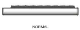

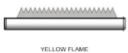
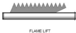
Normal Flame: A normal flame at 100% of burner input is blue, with slight yellow tips, a well defined flame and no flame lifting.
Yellow Tip: Yellow tipping can be caused by blockage or partial obstruction of air flow to the burner.
Yellow Flames: Yellow flames can be caused by blockage of primary air flow to the burner or excessive gas input. This condition MUST be corrected immediately.
Lifting Flames: Lifting flames can be caused by over firing the burner, excessive primary air or high draft.
If improper flame is observed, examine the venting system, ensure proper gas supply and adequate supply of combustion and ventilation air.
Check flue gas passageways
Any sign of soot around the inner jacket, outer jacket, flue pipe connections, burner or in the areas between the fins on the copper heat exchanger indicates a need for cleaning. The following cleaning procedure must only be performed by a qualified serviceman or installer. Proper service is required to maintain safe operation. Properly installed and adjusted units seldom need flue cleaning.
NOTICE
All gaskets/sealants on disassembled components or jacket panels must be replaced with new gaskets/sealants on reassembly. Gasket and sealant kits are available from your distributor.
CAUTION
When a Category IV vent system is disconnected for any reason, the flue must be reassembled and resealed according to the vent manufacturer's instructions.
Inspect and clean burner
- Turn off main power to unit.
- Turn off main manual gas shutoff to unit.
- Remove the front outer jacket panels.
- Disconnect manifold from gas train using union(s) just below each gas valve(s).
- Remove mounting screws from manifold mounting brackets. Pull the manifold/orifice assembly away from burners. Repeat for each manifold assembly.
- Remove two mounting screws from burner and slide burner out toward front of unit. Use caution to prevent damage to burners, refractory, hot surface igniter or wiring.
- Remove soot from burners with a stiff bristle brush.
Dirt may be removed from burner ports by rinsing the burner thoroughly with water. Drain and dry burners before re-installing. Damaged burners must be replaced.
When installed in a dusty and dirty location, the burners may require cleaning on a 3 to 6 month schedule or as needed, based on severity of contamination. Contaminants can be drawn in with the combustion air. Non combustible particulate matter such as dust, dirt, concrete dust or dry wall dust can block burner ports and cause non-warrantable failure. The standard inlet air filter will help eliminate dust and dirt from entering the unit. Use extreme care when operating a unit for temporary heat during new construction. The burners could require a thorough cleaning before the unit is placed in service.
8 Maintenance (continued)
Inspect and clean the heat exchanger
- While burners are removed, check the heat exchanger surface for sooting. If present, heat exchanger must be cleaned and problem corrected. Proceed as follows.
- Remove gas manifold(s)/orifice assemblies as described in steps 1 through 5 in Burner Removal and Cleaning, page 62.
- Disconnect wiring from the hot surface igniter and remove igniter from the door panel to prevent damage to the igniter.
- Remove inner jacket panel mounting screws and slide door assembly out toward front of the unit. Use caution to prevent damage to the refractory.
- Check "V" baffles and frame runners along front and back edges of heat exchanger. Remove and clean if necessary.
- Remove soot from heat exchanger with a stiff bristle brush. Use a vacuum to remove loose soot from surfaces and inner chamber.
- If necessary, the heat exchanger can be removed. Once the heat exchanger is removed from the unit, a garden hose can be used to wash the tubes to ensure that all soot is removed from the heat exchanger surfaces. Note: Do not wet the unit's refractory.
- Ensure that all burner ports are cleaned to remove any soot. See Burner Removal and Cleaning, page 62.
- Carefully reinstall the heat exchanger, "V" baffles, and frame runners if removed from the unit. Note: Make sure frame runners seal securely where they contact the front and rear compartment refractory.
- Carefully reinstall inner jacket panels, burners, manifolds, wires and hoses. Use new gasket material to ensure a proper air seal.
- Reassemble all gas and water piping. Test for gas leaks.
NOTICE
Upon completion of any testing on the gas system, leak test all gas connections with a
soap and water solution while main burners are operating. Do not spray soap and water solution on the CXi™ control module housing. The use of an excessive amount of soap and water solution can damage the control. Immediately repair any leak found in the gas train or related components. Do not operate an appliance with a leak in the gas train, valves, or related piping.
- Reassemble outer jacket panels.
- Cycle unit and check for proper operation.

text_image
Jagahi CXi HEAT EXCHANGERFigure 8-2_Location of the Heat Exchanger Inside Jacket
Review with owner
- Review the Jandy® CXi™ Installation and Operation Manual with the owner.
- Emphasize the need to perform the maintenance schedule specified in this manual.
- Remind the owner of the need to call a licensed contractor should the appliance or system exhibit any unusual behavior.
- Remind the owner to follow the proper shutdown procedure and to schedule an annual start-up at the beginning of the next heating season.
9 Connection diagram

flowchart
graph TD
    subgraph Main Power Harness
        A["IND-DHW PUMP RELAY COIL R 120V"] --> B["MAIN POWER HANNESS"]
        C["SYSTEM PUMP RELAY COIL R 120V"] --> B
        D["1HP UNIT MAX PUMP"] --> B
        E["120V/60Hz NEUTRAL SUPPLY LINE"] --> B
        F["GROUND"] --> B
    end

    subgraph Digital Harness
        G["CONTROLER FUSE AMPS F2= F4= F5= F6="] --> H["DISPLAY"]
        I["LOW VOLT HARNESS"] --> H
        J["MINI HARNESS"] --> H
    end

    B --> K["OPT. MODBUS HANNESS"]
    B --> L["CONTROLLER XFMR"]
    B --> M["CKT. BREAKER"]

    subgraph Control
        N["FUS AMPS F2= F4= F5= F6="]
        O["DISELAR HARNESS"] --> P["FUS AMPS F2= F4= F5= F6="]
        Q["CONTROLER FUSE AMPS F2= F4= F5= F6="]
    end

    style Main Power Harness fill:#f9f,stroke:#333
    style Digital Harness fill:#bbf,stroke:#333
NOTE: Not all connections/features apply to pool heaters.
9
Connection diagram (continued)

text_image
Notes: 1. All wiring must be installed in accordance with : local, state, provincial and national code requirements per either N.E.C. in USA or C.S.A. in Canada. 2. If any original equipment wire as supplied with the appliance must be replaced , it must be replaced with wire having same wire gauge (AWG) and rated for a minimum of 105°C 3. Actual connector block locations may vary from those shown on diagrams . Refer to actual components for proper connector block locations when using diagrams to trouble shoot unit . OPT. ALARM LOW VOLTAGE HARNESS LWBK 1 BL 2 Y O-BK T FLW SWITCH O/BK R O/BK P NO COM AIR PROVE SWITCH O/BK O/BK O/BK CHASSIS GROUND LWCO 24VAC TEST LWCO PROBE RESET PR- PR- Connection Board SILENCING SWITCH ALARM BELL ALARM RELAY 120VAC COIL DIGITAL HARNESS GROUNDEDING OPTION JUMPER TO CONNECTION BOARD MODBUS ADAPTER FACTORY OPTIONS FIELD OPTIONS WIRE COLOR REFERENCE W = WHITE T= TAN BK = BLACK Y=YELLOW PR=PURPLE BR=BROWN BL=BLUE G=GREEN P=PINK GY=GRAY O=ORANGE R=RED Y/G = YELLOW WITH GREEN STRIPE LBL20082 REV E IDENTIFICATION PLUG MODEL SPECIFIC CONSULT FACTORY NOTE: NUMBER OF GAS VALVES Varies BY MODEL R Y R 1 2 3 S1 R Y R 1 2 3 S1 R/BKY R/BK 1 2 3 S2 R/O Y R/O 1 2 3 S3 R/O Y R/O 1 2 3 S3 R/W Y R/W 1 2 3 S4 S4 6 STAGE #1 STAGE#2#1 STAGE #3 STAGE #4STAGE #3 BURNER GROUND -GY- -GY- #1 HSI GND GY/W GND GY/W GND GND GND GND GND GND GND GND GND GND GND GND GND GND GND GND GND GND GND GND GND GND GND GND GND GND GND GND GND GND GND GND GND GND GND GND GND GND GND GND GND GND GND GND GND GND GND GND GND GND GNP MAIN UNIT HARNESS DANGER TO PREVENT ELECTRICAL SHOCK THIS HEATER MAY BE CONNECTED TO MORE THAN ONE BRANC H CIRCUIT. MORE THAN ONE DISCONNECT SWITCH MAYBE REQUIRED TO DEENERGIZE THE EQUIPMENT FOR SERVIÇING10 Ladder diagram
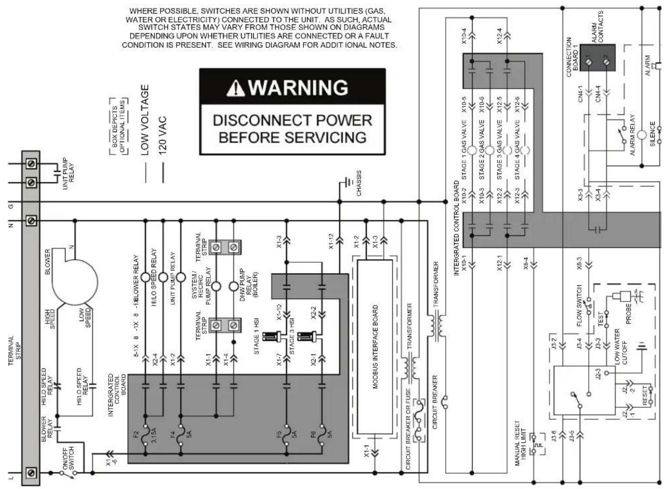
text_image
L TERMINAL STRIP N G ON/OFF SWITCH BLOWER RELAY HI/LO SPEED RELAY HIGH SPEED BLOWER HI/LO SPEED RELAY LOW SPEED N UNIT PUMP RELAY INTERGRATED CONTROL BOARD 8-1X 8 -1X 8 -1X BLOWER RELAY HI/LO SPEED RELAY UNIT PUMP RELAY F2 3.15A F4 5A X1-1 X1-4 X1-7 X1-10 X1-3 X2-1 X2-2 X1-12 STAGE 1 HSI STAGE 3 HSI X1-1 X1-3 X1-12 MODBUS INTERFACE BOARD CHASSIS CIRCUIT BREAKER OR FUSE TRANSFORMER CIRCUIT BREAKER TRANSFORMER INTERGRATED CONTROL BOARD X10-1 X10⁻² STAGE 1 GAS VALVE X10-5 X10⁻³ STAGE 2 GAS VALVE X10-6 X12-1 X12-2 STAGE 3 GAS VALVE X12-5 X12-4 X5-4 X12-3 STAGE 4 GAS VALVE X12-5 X12-4 J3-6 J3-5 J3-2 J3-4 FLOW SWITCH X6-3 X3-3 CN4-1 ALARM J2-3 TEST LOW WATER CUTOFF PROBE J2-1 RESET SILENCE ALARM DISCONNECT POWER BEFORE SERVICING A WARNING WHERE POSSIBLE SWITCHES ARE SHOWN WITHOUT UTILITIES (GAS, WATER OR ELECTRICITY) CONNECTED TO THE UNIT AS SUCH ACTUAL SWITCH STATES MAY VARY FROM THOSE SHOWN ON DIAGRAMS DEPENDING UPON WHETHER UTILITIES ARE CONNECTED OR A FAULT CONDITION IS PRESENT. SEE WIRING DIAGRAM FOR ADDITIONAL NOTES. CONNECTION BOARD 1NOTE: Not all connections/features apply to pool heaters.
10
Ladder diagram (continued)
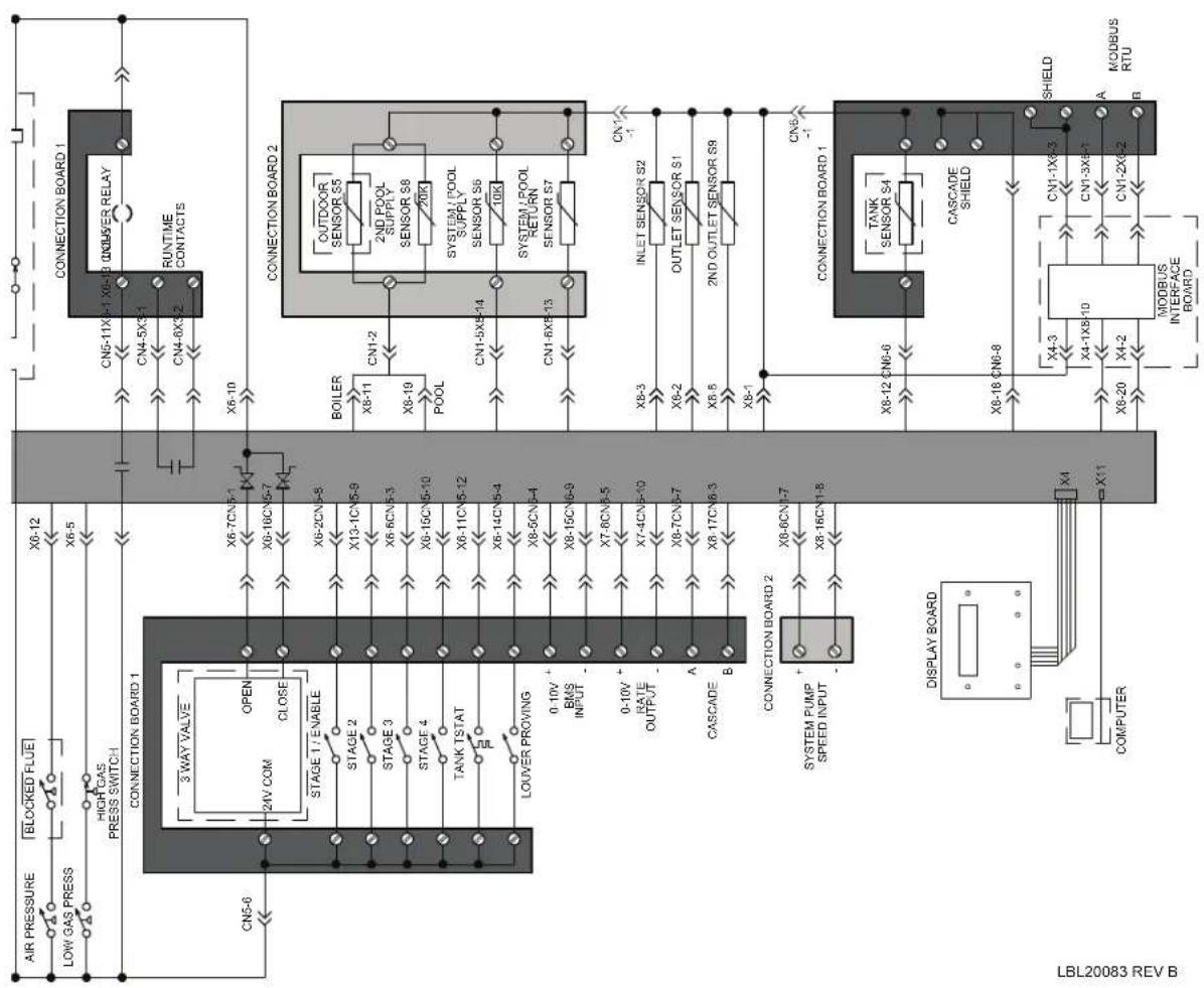
flowchart
graph TD
    A["AIR PRESSURE"] --> B["BLOCKED FLUE"]
    B --> C["X6-12"]
    C --> D["LOW GAS PRESS"]
    D --> E["X6-5"]
    E --> F["HIGH GAS PRESS SWITCH"]
    F --> G["3 WAY VALVE"]
    G --> H["OPEN"]
    H --> I["X6-7CN5-1"]
    I --> J["X6-10"]
    J --> K["CONNECTION BOARD 1"]
    K --> L["CONN5-11X-1 X6-13 OUTDOOR RELAY"]
    L --> M["CRNTIME CONTACTS"]
    M --> N["CONNECTION BOARD 2"]
    N --> O["OUTDOOR SENSOR S5"]
    O --> P["2ND POOL SUPPLY SENSOR S8"]
    P --> Q["20K"]
    Q --> R["SYSTEM / POOL SUPPLY SENSOR S6"]
    R --> S["10K"]
    S --> T["SYSTEM / POOL RETURN SENSOR S7"]
    T --> U["CONNECTION BOARD 1"]
    U --> V["TANK SENSOR S4"]
    V --> W["CASCADE SHIELD"]
    W --> X["X4-3"]
    X --> Y["X4-1X8-10"]
    Y --> Z["X4-2"]
    Z --> AA["X4-20"]
    AA --> AB["MODBUS INTERFACE BOARD"]
    AB --> AC["X1-1X6-3"]
    AC --> AD["SHIELD"]
    AD --> AE["X1-2X6-2"]
    AE --> AF["A MODBUS RTU"]
    AF --> AG["B"]
    AG --> AH["COMPUTER"]
    AH --> AI["DISPLAY BOARD"]
    AI --> AJ["X1-1X6-3"]
    AJ --> AK["X4-3"]
    AK --> AL["X4-1X8-10"]
    AL --> AM["X4-20"]
    AM --> AN["X4-20"]
    AN --> AO["X4-20"]
    AO --> AP["X4-20"]
    AP --> AQ["X4-20"]
    AQ --> AR["X4-20"]
    AR --> AS["X4-20"]
    AS --> AT["X4-20"]
    AT --> AU["X4-20"]
    AU --> AV["X4-20"]
Th is page intentionally left blank.
11 Start-up checklist
CXi POOL HEATER START-UP CHECKLIST
Job Name:
Address:
City: ____ ST: ____ Zip: ____
OVERVIEW
Retrofit New Project
How many units are installed at this location?
Boiler(s):
Water Heater(s):
Inspect gas pipe, regulator and meter sizing.
Is it sized correctly for Y Btu/Hr requirement? N
Total Equiv. Length Gas Piping:
GAS SUPPLY
Gas Pipe Dia. (in.):
Is there an inlet gas lockup Y regulator on the supply? N
If Yes, is it ten feet upstream from the appliance? Y N
Record in. of water column - Static Pressure:
Dynamic Pressure:
Manifold Pressure:
Air Pres. Differential:
Model Number: ____
Serial Number:
Start-up Date: ____
WATER SUPPLY
Water Pipe
Dia. (in.):
Set Point:
Differential:
At full fire, read and record -
Inlet Temp:
OutletTemp:
Delta T:
ELECTRICAL
Supply Voltage: ____
Total Amp Draw:
External Remote?
Which contacts are used?
Ws
Wp
R
Other:
VENTING (Select the venting option being used):
Outdoor
Conventional venting - Single pipe vertical termination
E-Rite Sidewall direct vent - Two pipe sidewall termination
Powered Sidewall - Single pipe sidewall termination
Powered DirectAire Horizontal - Two pipe sidewall termination
DirectAire Vertical w/rooftop inlet - Two pipe vertical termination
DirectAire Vertical w/sidewall inlet - Single pipe vertical and single pipe sidewall termination
Other:
COMBUSTION AND VENTILATION OPENINGS:
Two openings to outside
Two ducts from outside
One opening to outside
Two ducts from interior space
Combustion & Vent
Openings (total sq. in.):
Louver Openings
(total sq. in.):
Clearance between
inlet & outlet (DV):
Comments/Corrections for air inlet piping, openings, or venting:
CLEARANCES Measure and record (inches) the service clearances from the nearest obstruction (min. 24" required for service):
Front: ____ L Side: ____ Top: ____
Rear: ____ R Side: ____
Corrections needed or General Job Notes:
Send completed form to:
Email:
Fax:
Mail:
Jandy®
-- The information on this form verifies operation of the Jandy® product only.
This does not imply other system components or overall system operation is certified. Component and system verification should be performed by the designated commissioning agent or installing contractor.
COMBUSTION
Low Fire: High Fire:
O_2%
COppm
CO_2%
Draft Readings
Record in. of water column -
Unit On:
Unit Off:
Barometric Dampers properly adjusted? Y N
WARNING! This Startup Sheet is for use only by a qualified heating installer/service technician. Refer to the Installation and Operation Manual for your reference. Have this unit serviced/inspected by a qualified service technician, at least annually. Failure to comply with the above could result in severe personal injury, death, or substantial property damage.
START-UP PERFORMED BY:
Company:
Name:
Phone: ____
START-UP APPROVED BY:
Company:
Name:
Phone:
Internal Use:
S/O #:
Routed:
Tech:
App: Denied:
©2019 Zodiac Pool Systems LLC. All rights reserved. All other trademarks are the property of their respective owners.
Revision Notes: Revision A (PCP #3000035644 / CN #500024063) initial release.
Revision B (PCP #3000038111 / CN #500026291) reflects a change to the location of the start-up form.
Revision C (PCP #3000044690 / CN #500032479) reflects a general update to 2021 water heater standards.
Revision D (PCP #3000047058 / CN #500034438) reflects updates to the CSA/ANSI standards on page 8.
100320962_2000575058_Rev D