P825 - Pool POLARIS - Free user manual and instructions
Find the device manual for free P825 POLARIS in PDF.


User questions about P825 POLARIS
0 question about this device. Answer the ones you know or ask your own.
Ask a new question about this device
Download the instructions for your Pool in PDF format for free! Find your manual P825 - POLARIS and take your electronic device back in hand. On this page are published all the documents necessary for the use of your device. P825 by POLARIS.
USER MANUAL P825 POLARIS
natural_image
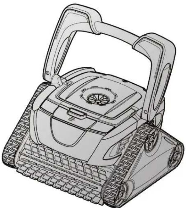
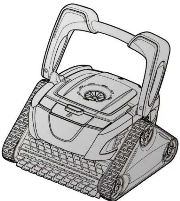
Line drawing of a tracked robotic device with visible wheels and handle (no text or symbols)P825 Robotic Pool Cleaner
TYPE EM27--
OWNER'S MANUAL
ENGLISH | FRANÇAIS | ESPAÑOL
WARNING
FOR YOUR SAFETY - For anything other than the routine cleaning and maintenance described in this manual, this product must be serviced by a contractor who is licensed and qualified in pool equipment by the jurisdiction in which the product will be installed where such state or local requirements exist. In the event no such state or local requirement exists, the maintainer must be a professional with sufficient experience in pool equipment installation and maintenance so that all of the instructions in this manual can be followed exactly. Improper installation and/or operation will void the warranty.
Table of Contents
Section 1. Important Safety Instructions......3
Section 2. Cleaner Specifications ....4
Section 3. Assembly and Setup .... 4
3.1 Unpacking 4
3.2 Assembling the Transport Caddy .... 4
3.3 Connecting the Control Unit to the Caddy......6
3.4 Connecting to a Power Source....6
Section 4. Operation....7
4.1 The Polaris P825 Cleaner Control Unit .... 8
4.2 Submerging the Cleaner 8
4.3 Starting the Cleaner 9
4.4 Wall Cleaning (Surface Control System ^TM )......9
4.5 Stopping the Cleaner and Removing from the Pool....10
4.6 Rinsing the Cleaner....10
4.7 Cleaning the Filter Canister....10
4.8 Storing the Cleaner 11
Section 5. Maintenance....12
5.1 Cord Tangling 12
5.2 Replacing the Brushes 13
5.3 Replacing the Tracks....14
Section 6. Replacement Parts .... 14
Section 7. Troubleshooting .... 15
7.1 Using the Cleaner Error Indicator....15
7.2 General Troubleshooting 16
THANK YOU FOR PURCHASING THE POLARIS CLEANER.
YOUR POLARIS ROBOTIC CLEANER HAS BEEN DESIGNED AND MANUFACTURED TO BE EASILY INSTALLED AND TO PROVIDE LOW MAINTENANCE OPERATION. PRIOR TO INSTALLING YOUR NEW POLARIS CLEANER, PLEASE DO THE FOLLOWING:
1) Complete and return the warranty registration card.
2) Record your purchase information on the spaces provided below.
3) Attach your invoice (or a copy) to this page.
Taking these steps will help ensure prompt warranty service, should it be required. If service is required, please contact your original dealer. If the original dealer does not perform warranty service, please visit www.polarispool.com to locate an independent service company near you. If you are unable to locate a service company, please call our Technical Support department at 1-800-822-7933.
RECORD YOUR POLARIS CLEANER DATA HERE:
Date of Purchase ____ Purchased From ____ Serial Number: ____
(located on machine head)
City ____ State/Province ____ Zip/Postal Code ____
Section 1. Important Safety Instructions
Congratulations on purchasing the Polaris Robotic Cleaner. Please read through the entire manual before installing your new robotic pool cleaner. Your cleaner must be installed and operated as specified.
READ AND FOLLOW ALL INSTRUCTIONS
WARNING
Failure to comply with the following warnings can result in permanent injury, electrocution or death.
PREVENT ELECTRICAL SHOCK
To reduce risk of electrical shock:
- Connect unit to receptacle protected by a ground fault circuit interrupter (GFCI). Such a GFCI receptacle should be provided by a qualified installer and should be tested on a routine basis. To test the GFCI, push the test button. The GFCI should interrupt power. Push the reset button. Power should be restored. If the GFCI fails to operate in this manner, the GFCI is defective. If the GFCI interrupts power to the pump without the test button being pushed, a ground current is flowing, indicating the possibility of an electric shock. Do not use this product. Disconnect the cleaner and have the problem corrected by a qualified service representative before using.
- Per the United States National Electrical Code ^ (NEC ^ ), keep the control unit at least five (5) feet from the edge of the (pool/spa) water. In Canada, the Canadian Electrical Code (CEC) requires a minimum distance of 3m (10 ft.) to be maintained between the pool edge and the control unit. Never submerge the control unit.
- Do not enter pool while the Polaris cleaner is in water.
- Do not bury cord. Locate cord so as to prevent it from being damaged by lawn mowers, hedge trimmers and other equipment.
- To reduce the risk of electrical shock, do not use the Polaris robotic cleaner or control unit if the cord is worn or damaged. Contact Zodiac Pool Systems, Inc. Technical Support immediately for proper servicing and replacement of the damaged cord.
- Double insulation—For continued protection against possible electric shock, use only identical replacement parts when servicing. Do not attempt repair of the Polaris robotic cleaner, control unit, power cord, or floating cable.
• NEVER OPEN CONTROL UNIT. - DO NOT USE AN EXTENSION CORD TO CONNECT THE UNIT TO ELECTRIC SUPPLY; PROVIDE A PROPERLY LOCATED GFCI RECEPTACLE. THE CONTROL UNIT SHOULD BE PLACED NEAR THE GFCI RECEPTACLE BOX.
PREVENT CHILD INJURY AND DROWNING
• To reduce the risk of injury, do not permit children to operate this product.
- Do not let anyone, especially small children, sit, step, lean, or climb on any equipment installed as part of your pool's operational system.
CAUTION
Failure to comply with the following warnings could cause damage to pool equipment or personal injury.
- The Polaris cleaner must be installed and operated as specified.
- This product is intended for use with permanently-installed pools. Do not use with storable pools. A permanently-installed pool is constructed in or on the ground or in a building such that it cannot be readily disassembled for storage. A storable pool is constructed so that it is capable of being readily disassembled for storage and reassembled to its original integrity.
- Clean the filter canister in the Polaris cleaner after each use.
- Do not use the product in your pool if the water temperature is above 95^ (35°C) or below 55^ (13°C).
CAUTION
USE OF THE POLARIS ROBOTIC CLEANER IN A VINYL LINER POOL
Certain vinyl liner patterns are particularly susceptible to rapid surface wear of pattern removal caused by objects coming into contact with the vinyl surface, including pool brushes, pool toys, floats, fountains, chlorine dispensers, and automatic pool cleaners. Some vinyl liner patterns can be seriously scratched or abraded simply by rubbing the surface with a pool brush. Ink from the pattern can also rub off during the installation process or when it comes into contact with objects in the pool. Zodiac Pool Systems, Inc., is not responsible for, and the Limited Warranty does not cover, pattern removal, abrasion or markings on vinyl liners.
Section 2. Cleaner Specifications
| Control box supply voltage | 100-240VAC, 60 Hz |
| Supply voltage 30 V | DC |
| Installed load 150 W | max |
| Cable length 50 ft (15 m) | |
| Cleaner size (WxDxH) | 16 x 16.5 x 10 in. (41 x 42 x 25 cm) |
| Weight of Cleaner 20 | Ibs. (9 kg) |
| Filtration | All-purpose filter canister |
| Cycle lengths 1.5 hr | |
The cleaner is a double-insulated product. A double-insulated electrical appliance is one which has been designed in such a way that it does not require a safety connection to ground. The basic requirement for double-insulation is that no single failure can result in dangerous voltage becoming exposed so that it might cause an electric shock and that this is achieved without relying on an earthed (grounded) metal casing. This is achieved by having two (2) layers of insulating material surrounding live parts or by using reinforced insulation. Therefore, devices having double-insulated construction, such as this cleaner, do not utilize a grounded (three-prong) cord/plug.
Section 3. Assembly and Setup
3.1 Unpacking
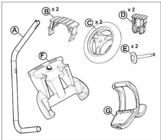
The packaging should contain the following items:
- Robotic cleaner and floating power cable
• Control unit with power cord - Transport and storage caddy assembly components (Figure 1)
(a) handle frame
(b) support blocks (x 2)
(c) wheels (x 2)
(d) wheel locking clips (x 2)
(e) wheel axle / hubcap (x 2)
(f) base unit
(g) caddy handle
text_image
Technical diagram of a mechanical device with labeled parts A through G, including a multi-component assembly and a wheel.Figure 1. Transport Caddy Assembly Components
When unpacking the cleaner and its components:
- Check to make sure each component is in the box.
- Check cleaner and components for damage.
- If there are missing parts or damage, contact Polaris Technical Support:
USA 1-800-822-7933
Canada 1-888-647-4004.
3.2 Assembling the Transport Caddy
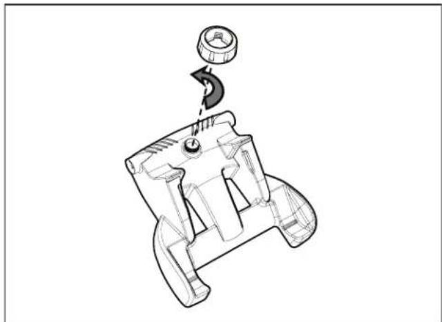
- Unscrew the handnut from the base unit (Figure 2).
natural_image
Technical line drawing of a mechanical component with a hook and circular head (no text or symbols)Figure 2. Remove Handnut from Base Unit
-
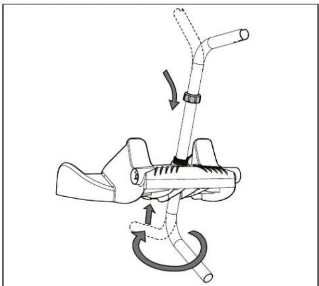
Insert the metal handle frame tubing into the base unit with notch end at the top, then rotate so the bends are away from you. (Figure 3).
-
Push base unit down (Figure 3) so the metal handle frame is seated in the recess on the underside of the base.
natural_image
Diagram of a mechanical device with a lever and curved arm, showing motion arrows (no text or symbols)Figure 3. Connect Metal Frame to Base Unit
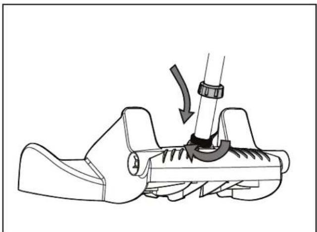
- Slide the handnut over the tube and twist to tighten onto base unit (Figure 4).
natural_image
Mechanical diagram showing a lever mechanism with a curved arrow indicating motion (no text or symbols present)Figure 4. Twist Handnut to Secure Frame
-
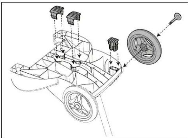
Snap two (2) support blocks into place (Figure 5).
-
Slide axle and hubcap piece through center of wheel and attach to base unit. Snap locking clip into place to secure wheel. Repeat to attach both wheels (Figure 5).
natural_image
Technical line drawing of a vehicle chassis with labeled components and assembly lines (no text or symbols)Figure 5. Snap in Support Blocks and Attach Wheels
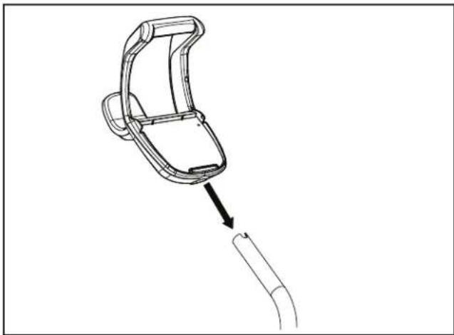
- Slide the control unit base / caddy handle attachment down over the metal tubing until it snaps into place. (See Figure 6).
natural_image
Line drawing of a mechanical device with a curved handle and a separate curved component, no text or symbols present.Figure 6. Attach Caddy Handle
natural_image
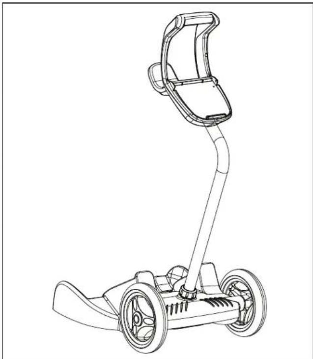
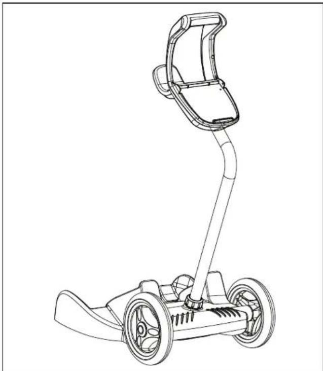
Line drawing of a mobility scooter with extended arm and wheels (no text or symbols)Figure 7. Fully Assembled Transport Caddy
3.3 Connecting the Control Unit to the Caddy
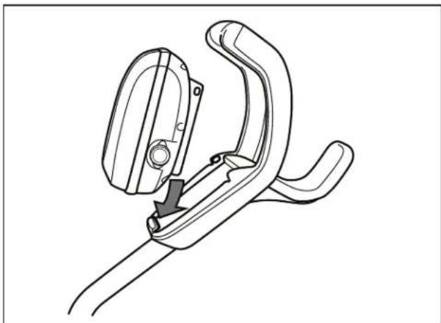
- Align the bottom of the control unit with the notch at bottom of the control unit hook on the caddy (Figure 8).
natural_image
Line drawing of a mechanical clamp or bracket assembly (no text or symbols)Figure 8. Align Control Unit on Caddy Hook
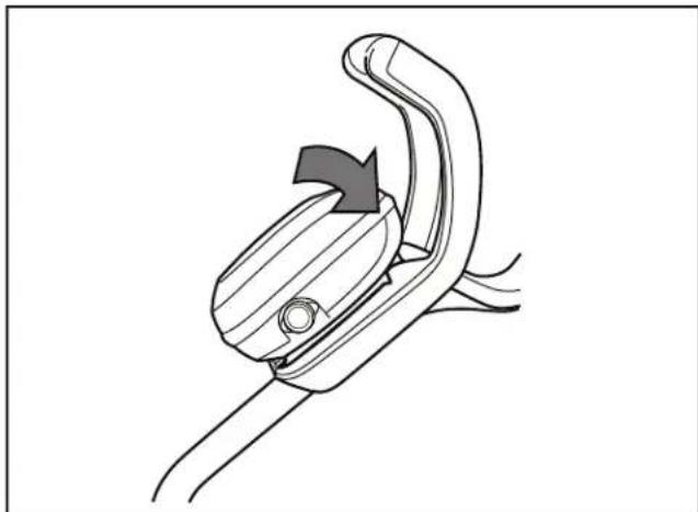
- Press control unit onto the caddy hook until it snaps and locks into position (Figure 9).
natural_image
Line drawing of a mechanical clamp or clip mechanism (no text or symbols)Figure 9. Attach the Control Unit onto Caddy
3.4 Connecting to a Power Source
WARNING
Failure to comply with the following warnings can result in permanent injury, electrocution or drowning.
PREVENT ELECTRICAL SHOCK
- U.S.: Per NEC® requirements, keep the control unit at least five (5) ft. (1.5 m) from the edge of the pool. CANADA: Per CEC requirements, keep the control unit at least three (3) m (10 ft.) from the edge of the pool.
- Only connect the control unit to a receptacle protected by a ground fault circuit interrupter (GFCI). Contact a certified electrician if you cannot verify that the receptacle is protected by a GFCI.
- Do not use an extension cord to connect the control unit.
- Do not allow anyone to swim while the cleaner is in the pool.
- The control unit is water-resistant, not waterproof. In order to prevent electrocution, never submerge the control unit or leave exposed to inclement weather.
To Connect:
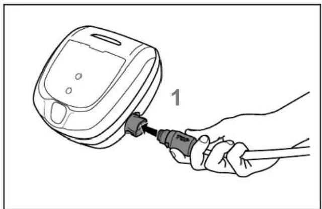
- Rotate the power cord so that TOP is shown on the top side. Press the power cord firmly into the control unit until you hear a "click" (see Figure 10). The clicking indicates the power cord is connected correctly creating a watertight seal.
natural_image
Line drawing of a hand holding a small device connected to a plug, with no visible text or symbols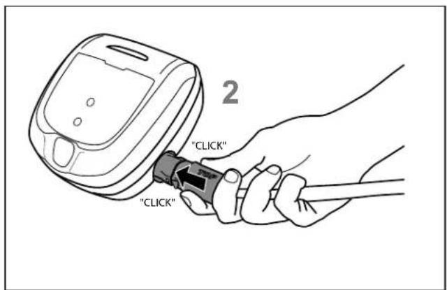
text_image
"CLICK" "CLICK" 2Figure 10. Connect the Power Cord
To Disconnect:
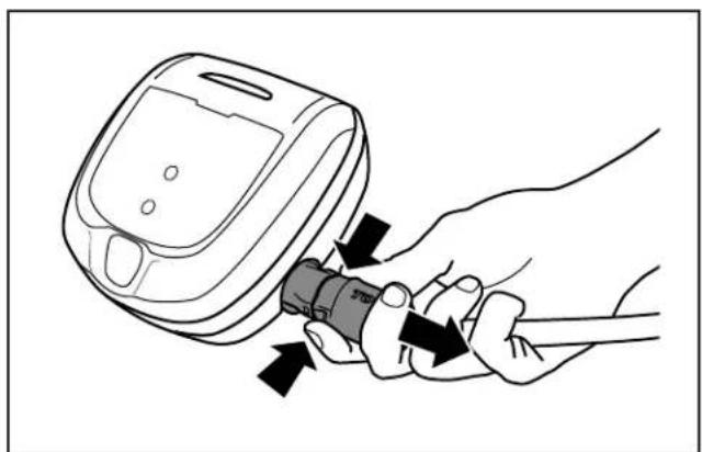
- Grip the power cord firmly on each side and press two tabs to release (see Figure 11.)
natural_image
Illustration of a hand inserting a plug into a device (no text or symbols present)Figure 11. Disconnect the Power Cord
Section 4. Operation
CAUTION
To prevent damage to the cleaner, be sure to adhere to the following guidelines:
- Remove the cleaner from the pool after the cleaning cycle is completed and store on the caddy out of direct sunlight or inclement weather.
- Never lift the cleaner out of the pool by the floating cable. Always use the handle to remove cleaner from the pool.
• Take additional care when lifting the cleaner out of the pool. It becomes heavier when filled with water.
• Always remove the cleaner from pool when super chlorinating or adding acid. - Do not handle cleaner while it is in operation.
IMPORTANT
• Always make sure the cleaner head is fully submerged before you begin operation.
- Clean the filter canister after each cleaning cycle.
- Do not leave your cleaner in the pool on a permanent basis.
- At the end of each cycle, remove the cleaner from the pool. Start at the cleaner head and untangle any coils in the cable before storing the cleaner.
When the control unit is powered on with the floating cable attached, the operating time for the current selected cycle is displayed.
The Polaris robotic cleaner includes a safety feature that automatically stops the cleaner if it is powered on but not submerged in water. For pools equipped with a beach area, this safety feature is programmed to drive the cleaner in reverse and back into the pool when the impeller is out of the water.
4.1 The Polaris P825 Cleaner Control Unit
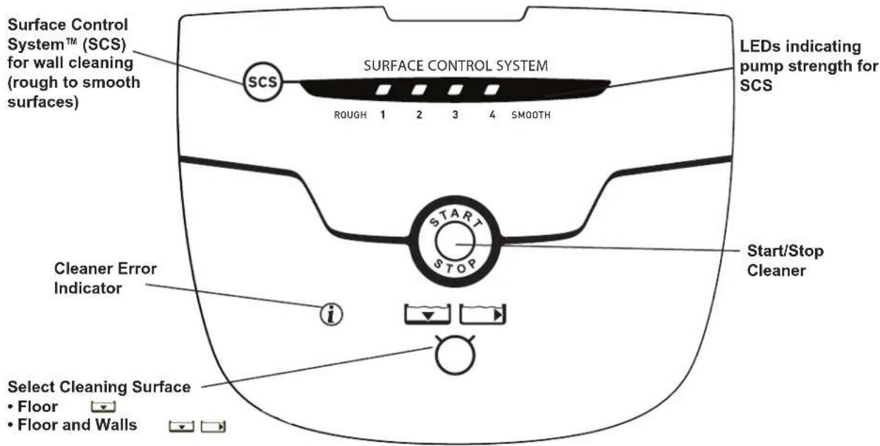
text_image
Surface Control System™ (SCS) for wall cleaning (rough to smooth surfaces) SCS SURFACE CONTROL SYSTEM ROUGH 1 2 3 4 SMOOTH LEDs indicating pump strength for SCS START STOP Cleaner Error Indicator Start/Stop Cleaner Select Cleaning Surface • Floor • Floor and Walls4.2 Submerging the Cleaner
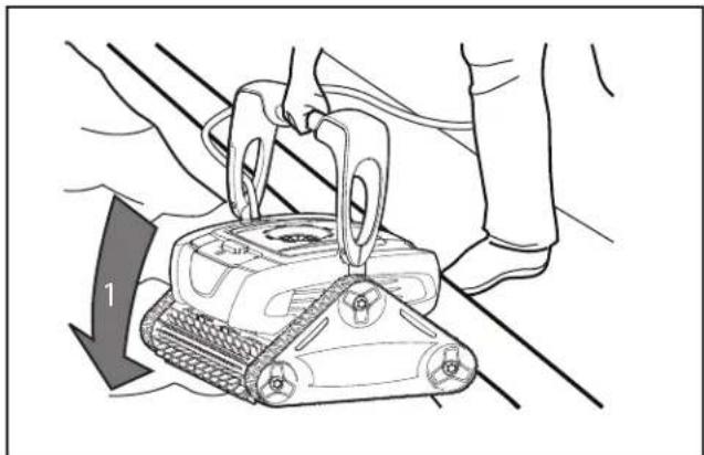
- Submerge the cleaner vertically (1) and hold it under the surface, moving gently from side to side (2) until the bubbles stop to remove any air trapped inside (see Figure 12).
- When the bubbles stop, allow the cleaner to sink to the bottom of the pool.
- Verify the cleaner is sitting on the bottom of the pool. Remove additional air if the cleaner is still floating.
NOTE: The cable side of the cleaner remains up as long as the pump is OFF. As soon as you turn the pump ON, the handle lowers.
natural_image
Illustration of a robotic device being adjusted for a tool, with a hand adjusting the component (no text or symbols present)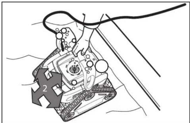
natural_image
Illustration of a robotic device with a hand operating it, showing mechanical components and a numbered arrow (no text or symbols present)Figure 12. Submerge and Remove Trapped Air
- Spread the floating cable over the pool, making sure there are no kinks or coils in the cable.
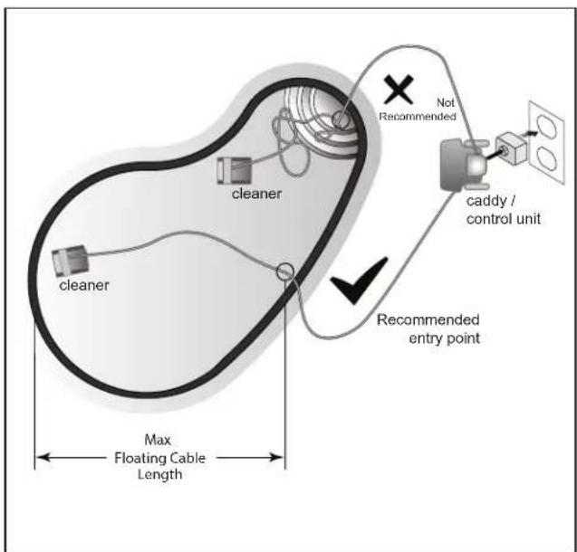
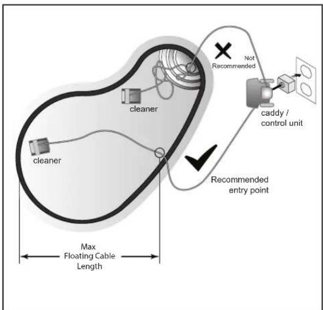
NOTE: For optimal patterning and reduced tangling, the floating cable should enter the water near the middle of the pool length. Only place enough cable in the water to reach the farthest point in the pool (see Figure 13).
text_image
cleaner cleaner Max Floating Cable Length Recommended entry point Not Recommended caddy / control unitFigure 13. Set Up for Optimal Patterning
4.3 Starting the Cleaner
The first time you use the cleaner, the cleaning surface setting is Floor and Walls
After the first time, the default is the last setting used.
Select Cleaning Surface:
- Use to change cleaning surface setting.

Begin Cleaning:
• After selecting the cleaning surface, press to begin operation.
- At the beginning of the cycle, the cleaner remains in place for a few seconds to initialize
the microcontroller after the pump starts.
NOTE: Periodically the cleaner will pause for up to 20 seconds throughout the cleaning cycle. The cleaner is calibrating its position in the pool during this process. This is normal operation and the cleaner will resume movement immediately after calibration with no user action required. The pause does not affect the overall cleaning cycle.
4.4 Wall Climbing (Surface Control System™)
The cleaner has the ability to clean the pool walls up to the waterline. How much the cleaner needs to grip to the wall depends upon the pool surface.
Grip Intensity Indicator:
Surface Control System (SCS) settings are as follows for different pool surface types:
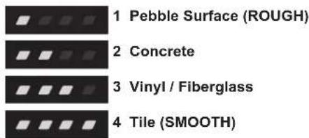
text_image
1 Pebble Surface (ROUGH) 2 Concrete 3 Vinyl / Fiberglass 4 Tile (SMOOTH)Check Wall Climbing Setting:
- Start the cleaner and watch as the cleaner climbs each wall. If grip setting is correct, the cleaner will easily climb the wall and clean up to the waterline. The default setting is
NOTE: Wall climbing is programmed in a randomized pattern. Cleaner may climb wall and not reach waterline until third or fourth attempt in order to thoroughly clean wall surface below the waterline first.
- Adjust the wall climbing setting as necessary using the following guidelines: Increase: if cleaner is climbing the wall slowly and stays below the waterline. Decrease: if cleaner is climbing the wall too quickly and sucking air at the waterline.
Adjust SCS Wall Climbing Setting:
You can change the wall climbing setting at any time during cleaner operation with the SCS button. The new setting will be active when the cleaner climbs the next wall.
- Press to adjust the wall climbing setting one level higher.
• One additional LED lights each time you press the button to indicate stronger grip on the wall.
• To decrease setting, press button to cycle through back to one LED (lowest setting).
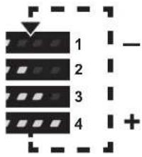
text_image
1 2 3 44.5 Stopping the Cleaner and Removing from the Pool
- If the cleaner is still in operation, press to interrupt operation. If cleaning cycle is complete, begin at Step 2.
- When the cleaner is within arm's reach, pull gently on the floating cable to bring the cleaner handle within arm's reach. Use the handle to lift the cleaner from the water (see Figure 14). Never lift the cleaner out of the pool by the floating cable.
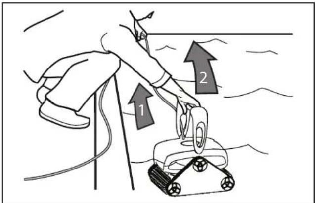
text_image
Diagram showing a robotic device with two upward arrows labeled 1 and 2, indicating movement or operation.Figure 14. Lift Cleaner From Pool with Handle
- Hold the cleaner vertically over the pool surface to drain water before removing (see Figure 15).
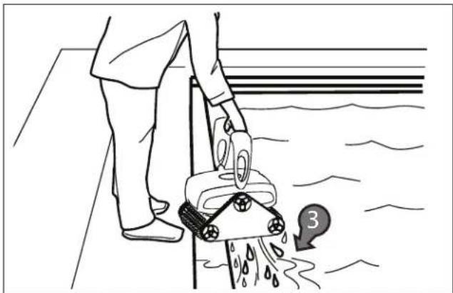
natural_image
Line drawing of a person using a cleaning robot to clean water, with a numbered callout (no text or symbols on the robot or floor)Figure 15. Lift Cleaner From Pool with Handle
4.6 Rinsing the Cleaner
Rinse the cleaner afer every cleaning cycle. Use slightly soapy clean water, then rinse generously with clean water. Do not use solvents such as acetone or its equivalent. Do not let your cleaner dry in direct sunlight near the pool.
4.7 Cleaning the Filter Canister
Always empty and clean the filter canister at the end of each cleaning cycle.
WARNING
To avoid electric shock and other hazards which could result in serious injury or death, disconnect (unplug) the cleaner from the power source before performing any cleaning and maintenance.
- Unplug power to the cleaner at the control unit. Unplug the control unit from the power source.
- Press the PUSH 'N' GO ^ button to release the filter canister handle (see Figure 16).
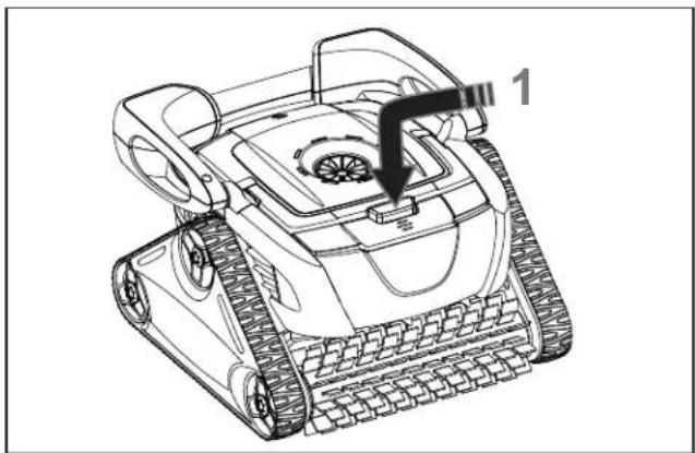
natural_image
Line drawing of a tracked robot with a labeled component (no text or symbols present)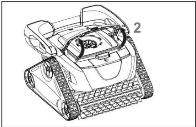
natural_image
Line drawing of a tracked robotic vehicle with visible wheels and a labeled component (no text or symbols present)Figure 16. Release Filter Canister Handle
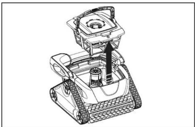
- Grasp the filter canister handle and lift up to remove the filter canister (see Figure 17).
natural_image
Technical line drawing of a robotic device with visible gears and wheels (no text or symbols)Figure 17. Remove the Filter Canister
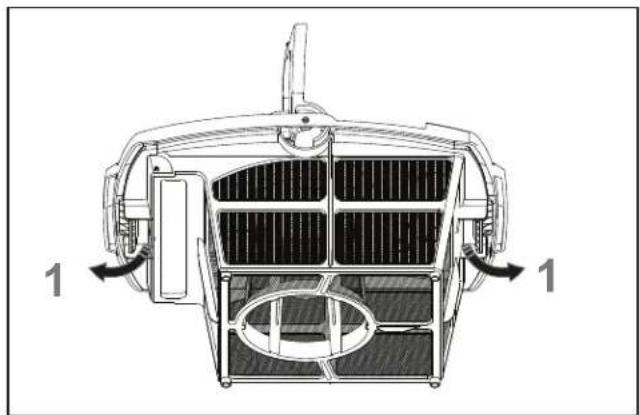
- Press two latches (1) and remove the filter canister lid (2) (See Figure 18).
natural_image
Technical line drawing of a vehicle front panel with internal compartments and directional arrows indicating movement (no text or symbols)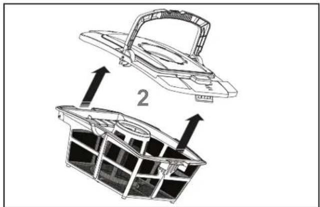
natural_image
Technical illustration of a mechanical device with two views: top shows a handle, bottom shows a grid-like structure (no text or symbols)Figure 18. Remove Filter Canister Lid
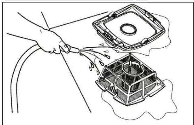
- Using a hose with clean water, rinse the filter canister and lid to remove all debris (see Figure 19).
natural_image
Line drawing of a hand holding a tool near a CPU socket and fan (no text or symbols)Figure 19. Rinse the Filter Canister
- Replace lid on the canister and then replace canister back into the cleaner body.
4.8 Storing the Cleaner
The cleaner must be cleaned regularly using slightly soapy clean water. Do not use solvents such as acetone or its equivalent. Rinse the cleaner generously using clean water. Do not let your cleaner dry in direct sunlight near the pool. The cleaner must be stored on its caddy so that it dries quickly.
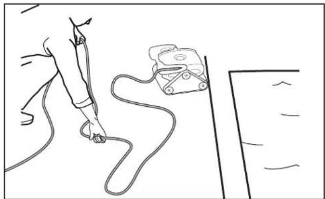
- Starting at the cleaner head. Remove all coils and tangles from the cable (see Figure 20).
natural_image
Line drawing of a person using a handheld device to connect cables, with no visible text or symbolsFigure 20. Untangle the Floating cable
-
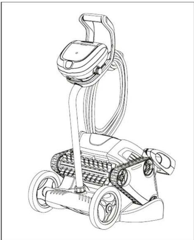
Place the cleaner in vertical position on the caddy base with the rear tracks on the caddy side wedges (see Figure 21).
-
Loosely coil the power cable starting at the cleaner and moving toward the connection point at control unit. Store the cable by wrapping it around the hook located on the front of the caddy (see Figure 21).
-
Disconnect the cable from the control unit and coil loosely around the caddy hook.
-
If you removed the control unit from the caddy, replace it by aligning the bottom of the control unit with the caddy notch, hook it onto the caddy, then press firmly in place until you hear a "click".
natural_image
Line drawing of a cleaning or cleaning robotic device with wheels and a handle (no text or symbols)Figure 21. Cleaner Stored Correctly on Caddy
Section 5. Maintenance
WARNING
To avoid electric shock and other hazards which could result in serious injury or death, disconnect (unplug) the cleaner from the power source before performing any cleaning and maintenance.
5.1 Cord Tangling
text_image
Cleaner cleaner Max Floating Cable Length Recommended entry point caddy / control unit Not RecommendedFigure 22. Spread Floating Cable Across Farthest Distance of the Pool
IMPORTANT
The floating cable may become tangled if correct procedure is not followed after each cleaning cycle.
Do not leave the cleaner unattended for prolonged periods and follow the procedure below to avoid excessive tangling.
After every cleaning cycle:
- Unplug power to the cleaner at the control unit.
- Remove the cleaner from the pool and untangle all kinks and coils in the floating cable starting at the cleaner head (see Figure 23).
- Plug power cord back into control unit and store cleaner on the caddy out of direct sunlight for next use.

natural_image
Line drawing of a person using a cable to connect a device on a surface, with no visible text or symbols.Figure 23. Untangle the Floating cable
5.2 Replacing the Brushes
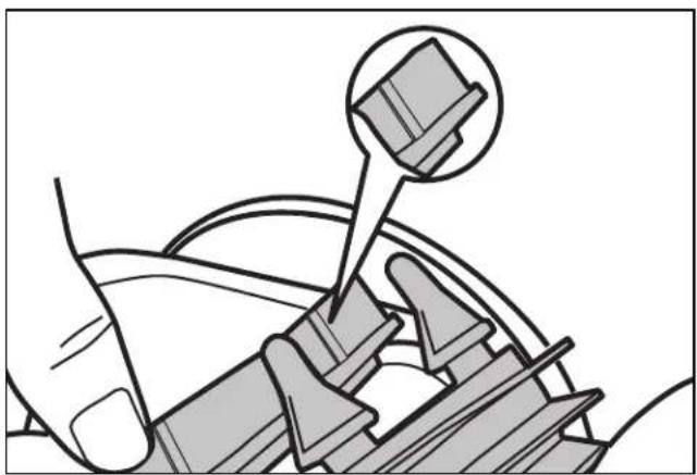
The cleaner is fitted with PVC brushes in front and rear. There are raised grooves that are "wear" indicators on the brushes located next to the tab connectors (see Figure 24). As brushes wear out, the raised groove will flatten and smoothen into the track. To maintain optimal cleaner performance, you should replace the brushes as soon as one of the wear indicators is smooth or worn down (even if the blade wear is not even). It is recommended that you replace the brushes every two (2) years.
natural_image
Diagram of mechanical assembly with a magnified inset showing a component (no text or symbols present)Figure 24. Wear Indicators
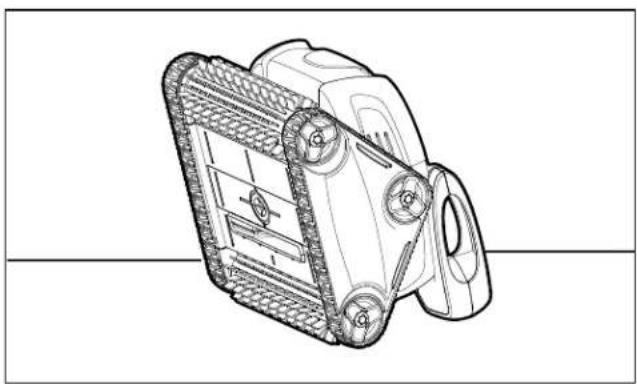
- Stand the cleaner on its end in a vertical position (see Figure 25).
natural_image
Technical line drawing of a mechanical device with gears and housing (no text or symbols)Figure 25. Stand Cleaner Upright
- Separate the edges of the brush, undo the tabs, and remove the worn brush.
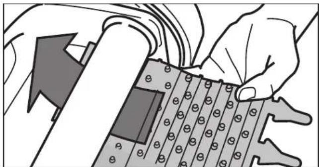
- Position the new brush underneath the roller with the spikes facing downwards (see Figure 26).
natural_image
Illustration of hands assembling a mechanical component with a grid pattern (no text or symbols)Figure 26. Position the New Brush on Roller
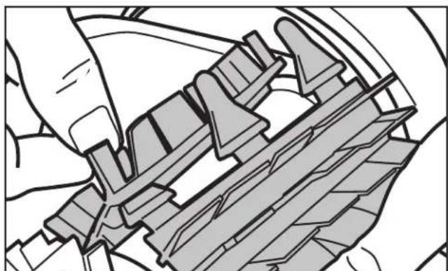
- Thread each tab into the slot provided and gently feed it through until the heel comes out at the other side of the slot (see Figure 27).
natural_image
Technical line drawing of a mechanical assembly or assembly (no visible text or symbols)Figure 27. Pull Tabs Through Each Slot
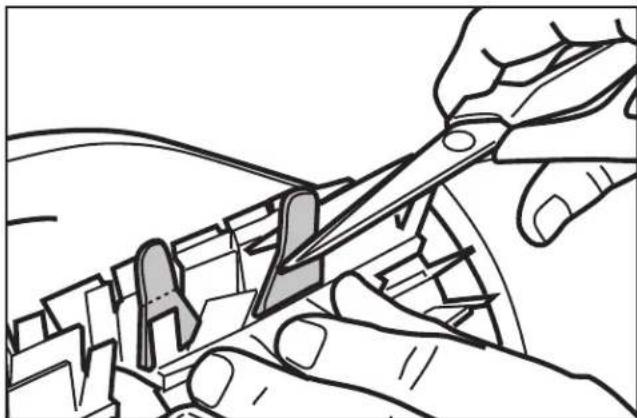
- Use scissors to cut the tabs so they are no higher than the spikes (see Figure 28).
natural_image
Line drawing of hands using a tool to cut or adjust mechanical components (no text or symbols present)Figure 28. Cut Tabs
- Repeat this procedure to replace the second brush.
5.3 Replacing the Tracks
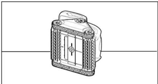
- Stand the cleaner on its side (see Figure 29).
natural_image
Technical line drawing of a mechanical component with textured surfaces and a central cross-section (no text or symbols)Figure 29. Stand Cleaner on its Side
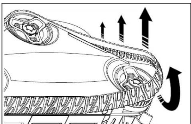
- Starting at one of the wheels, pull on the inside of the track to separate the tire lip from the wheel (see Figure 30). Remove the track from the cleaner.
text_image
Diagram illustrating airflow or traffic flow around a vehicle, with arrows indicating direction and speed changes.Figure 30. Pull the Track Over Wheels to Remove
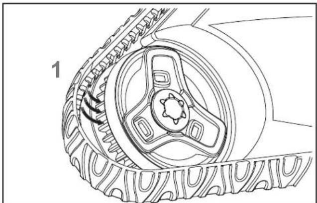
- To install a new track, place the inside rib of the track into the groove in the first wheel (see Figure 31).
natural_image
Technical line drawing of a mechanical component with gears and a central hub (no text or symbols)Figure 31. Position Track into Wheel Grooves
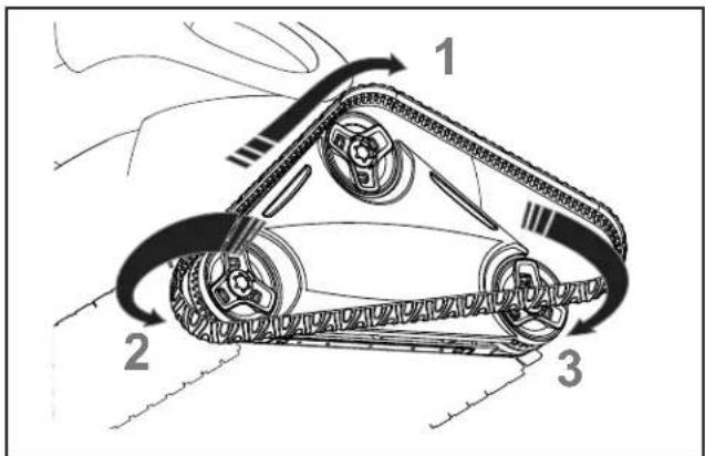
- Stretch the track around the second wheel, then pull over the last wheel (see Figure 32). Push and position the rib of the track so that the track is seated properly in the groove of the wheel.
text_image
Diagram of a tracked vehicle with labeled components and motion arrows indicating rotational movement.Figure 32. Stretch Track Around Wheels
- Verify the rib of the track is positioned properly within the groove of each of the three wheels. If necessary, turn the wheels gently to seat track.
Section 6. Replacement Parts
The complete spare parts list and exploded view is available on the Polaris website at www.polarispool.com. In Canada, parts list and exploded view is available at www.polarispool.ca
Section 7. Troubleshooting
7.1 Using the Cleaner Error Indicator
The Cleaner Error Indicator i on the control unit flashes in a specific sequence to indicate one of three possible cleaner malfunctions.
| Information LED Flashing Solution | |
| LED flashes once with one second interval. | Unplug the floating cable from the control unit and reconnect.If the problem is not resolved through troubleshooting, contact Polaris Technical Support at (USA) 1-800-822-7933; 1-888-647-4004 (Canada). |
| LED flashes twice with one second interval. | Turn cleaner wheels to ensure they are not jammed.Check brushes for debris.Start a new cleaning cycle.If the problem persists, contact Polaris Technical Support at (USA) 1-800-822-7933; 1-888-647-4004 (Canada). |
| LED flashes three times with one second interval. | Check the pump axis for debris.Check propellor for debris.Clean the filter.Start a new cleaning cycle.If the problem persists, contact Polaris Technical Support at (USA) 1-800-822-7933; 1-888-647-4004 (Canada). |
7.2 General Troubleshooting
The following table lists some of the common symptoms, causes, and solutions for correcting cleaner operation problems.
| Problem Cause Solution | ||
| The Cleaner Error Indicator flashes just after start (either pressing Power or Floor/ Wall setting button for less than 20 seconds). | Floating cable may not be plugged into the control unit correctly. | Unplug floating cable from the control unit and reconnect. |
| Cleaner may not be fully submerged. | Remove cleaner from the pool and re-submerge, see Submerging the Cleaner. | |
| Cleaner may need to be reset and begin a new cycle. | Press power button OFF, then Floor/Wall setting button to begin a new cycle. | |
| Propeller may be jammed and not turning correctly. | First contact your local retailer to request a diagnostic review, and if the problem is not resolved contact Polaris Technical Support at (USA) 1-800-822-7933.; 1-888-647-4004 (Canada). | |
| Tracks may be jammed and not turning correctly. | First contact your local retailer to request a diagnostic review, and if the problem is not resolved contact Polaris Technical Support at (USA) 1-800-822-7933.; 1-888-647-4004 (Canada). | |
| The Cleaner Error Indicator flashes during the cleaning cycle. | Cleaner may be sucking air (lights will appear after 60 seconds air intake). | Remove cleaner from the pool and re-submerge, see Submerging the Cleaner. |
| The cleaner does not stay firmly on the pool bottom. | There is air in the appliance casing. | Remove cleaner from the pool and re-submerge, see Submerging the Cleaner. |
| The filter canister is full or dirty. Clean | the filter canister, see Cleaning the Filter Canister. | |
| The impeller is damaged. First contact | your local retailer to request a diagnostic review, and if the problem is not resolved contactPolaris Technical Support at (USA) 1-800-822-7933.; 1-888-647-4004 (Canada). | |
| The cleaner does not climb the pool walls or clean up to the waterline. | The filter canister is full or dirty. Clean | the filter canister, see Cleaning the Filter Canister. |
| Walls of pool are slippery or slimy. Although the water seems clear, microscopic algae, invisible to the human eye, are present in the pool. As a result the pool walls become slippery and prevent the cleaner from climbing. Check tracks and brushes for wear and replace as necessary. | Adjust Surface Control System ^TM setting, see Wall Cleaning.Do a shock chlorination treatment to reduce the pH levels in the pool. DO NOT leave the cleaner in the pool during this treatment. | |
| On startup the cleaner does not move. | No power supply to the cleaner. Check | that the outlet to which the control unit is connected is receiving electricity. |
| Cleaner has shut down with error code or flashing lights. | Disconnect the control unit and wait at least 20 seconds before reconnecting.If the problem persists, contact Polaris Technical Support at 1-800-822-7933 (USA); 1-888-647-4004 (Canada). | |
| Cleaner stops up to 20 seconds during cleaning cycle. | Cleaner is performing normal calibration operation. | No user action required. The pause does not affect the overall cleaning cycle. |
| Cable is tangling in the pool | Too much cable length in the water. Do not unravel the entire cable. Use only the amount needed for the cleaner to cover the pool area.Place the remaining unused cable on the side of the pool. Follow the procedure in Cord Tangling to avoid and correct tangled cord. | |
| The cleaner is not cleaning effectively. | The brushes have become smooth or the "wear" indicator shows. | Replace the brushes following the procedure in Replacing the Brushes. |
| Filter canister is full or dirty. Clean the filter canister following the procedure in Cleaning the Filter Canister. | ||
| Floating cable is excessively coiled or kinked. | Make sure the floating cable is spread out over the pool. Ensure the cable is not too tightly wrapped or coiled when storing. If the problem persists, lay the cable straight in the sun to relax it and remove kinks. Follow the procedure in Cord Tangling to avoid and correct tangled cord. | |
NOTES
Zodiac Pool Systems, Inc.
2620 Commerce Way, Vista, CA 92081
1.800.822.7933 | www.ZodiacPoolSystems.com
POLARIS® and the Polaris 3-wheeled cleaner design are registered trademarks of Zodiac Pool Systems, Inc.
ZODIAO® is a registered trademark of Zodiac International, S.A.S.U., used under license. All other trademarks referenced herein are the property of their respective owners.
©2016 Zodiac Pool Systems, Inc. H0429900 Rev F
natural_image
Line drawing of a tracked robotic device with visible wheels and handle (no text or symbols)text_image
Technical diagram of a mechanical component with labeled parts A through G, including parts like brackets, wheels, and a handle.natural_image
Technical line drawing of a mechanical component with a hook and circular head (no text or symbols)natural_image
Mechanical diagram showing a lever mechanism with rotating shaft and guide rod (no text or symbols)natural_image
Mechanical diagram showing a lever mechanism with a rotating shaft and curved motion arrow (no text or symbols)natural_image
Technical line drawing of a vehicle chassis with labeled components and assembly lines (no text or symbols)natural_image
Line drawing of a car interior component with a hand pointing to a curved pipe or pipe fitting (no text or symbols)natural_image
Line drawing of a mobility scooter with extended arm and wheels (no text or symbols)natural_image
Technical line drawing of a mechanical clamp or bracket assembly (no text or symbols)natural_image
Line drawing of a mechanical clamp or clip mechanism (no text or symbols)natural_image
Line drawing of a hand holding a small device connected to a cable, with no visible text or symbols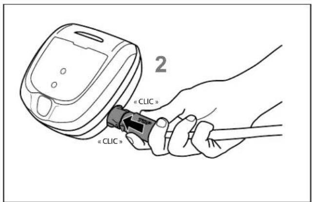
natural_image
Illustration of a hand holding a small device with arrows indicating cable or plug movement (no text or symbols)natural_image
Illustration of hands operating a mechanical device with a curved handle, no text or symbols present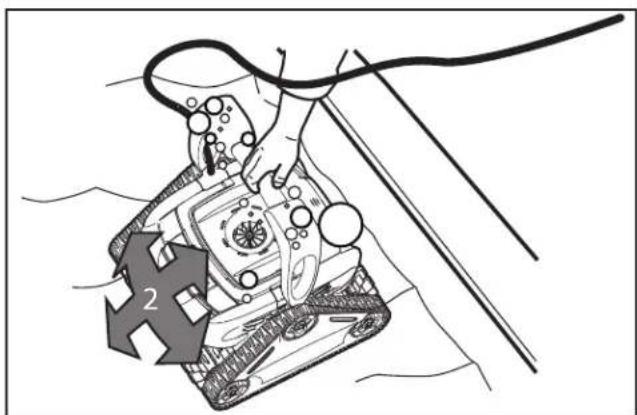
natural_image
Illustration of a robotic device with a numbered arrow pointing to it, no text or symbols presentIllustration 12.
text_image
Diagram showing a robotic device with two upward arrows labeled 1 and 2, indicating movement or operation in water.natural_image
Line drawing of a person using a cleaning robot to clean water, with a numbered callout indicating step 3 (no text or symbols on the robot or floor)natural_image
Line drawing of a tracked robot with visible mechanical components and a directional arrow (no text or symbols)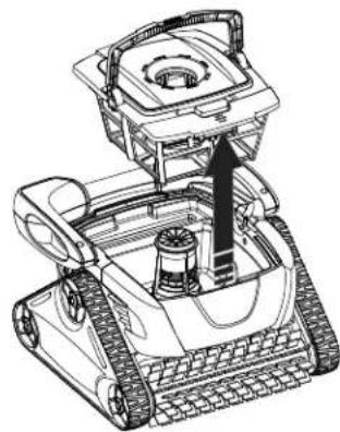
natural_image
Technical line drawing of a tracked robot with visible mechanical components and mounting base (no text or symbols)Illustration 17.
natural_image
Technical line drawing of a vehicle front panel with internal compartments and directional arrows indicating movement (no text or symbols)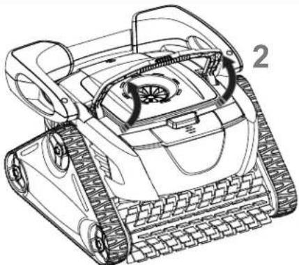
natural_image
Line drawing of a tracked robot with visible wheels and control panels (no text or symbols)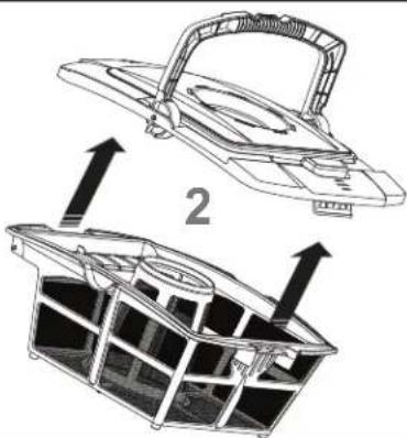
natural_image
Technical line drawing of a mechanical device with two views: top shows a handle, bottom shows a grid-like structure (no text or symbols)Illustration 16.
natural_image
Line drawing of a hand using a tool to clean or spray liquid into a container (no text or symbols)Illustration 19.
natural_image
Line drawing of a person using a cable to lift a mechanical device (no text or symbols)Illustration 20.
natural_image
Line drawing of a lawn mower with adjustable wheels and control panel (no text or symbols)natural_image
Line drawing of a person using a cable to connect a device on a surface (no text or symbols)Illustration 23.
natural_image
Illustration of mechanical components with a magnified view of a bracket (no text or symbols)natural_image
Technical line drawing of a mechanical device with gears and housing (no text or symbols)Illustration 25.
natural_image
Illustration of hands operating a mechanical component with a grid pattern and directional arrow (no text or symbols)Illustration 26.
natural_image
Mechanical assembly diagram showing hands assembling a component (no text or symbols visible)Illustration 27.
natural_image
Line drawing of hands using scissors to cut or trim a mechanical component (no text or symbols)Illustration 28.
natural_image
Technical line drawing of a mechanical component with internal structure and mounting holes (no text or symbols)Illustration 29.
text_image
Diagram illustrating airflow or mechanical process with arrows indicating direction and components, likely from a vehicle or industrial system.natural_image
Technical line drawing of a mechanical component with gears and a central hub (no text or symbols)text_image
Diagram of a robotic vehicle with labeled parts and motion arrows indicating rotational movement.Zodiac Pool Systems, Inc.
2620, Commerce Way, Vista, CA 92081
1-800-822-7933 | www.ZodiacPoolSystems.com
© 2016 Zodiac Pool Systems, Inc. H0429900 Rév F
natural_image
Line drawing of a tracked robotic device with visible wheels and handle (no text or symbols)natural_image
Technical line drawing of a mechanical component with a hook and circular head (no text or symbols)natural_image
Mechanical diagram showing a lever mechanism with rotating components and directional arrows (no text or symbols)natural_image
Mechanical diagram showing a lever mechanism with a rotating shaft and guide mechanism (no text or symbols)natural_image
Technical line drawing of a vehicle chassis with labeled components and assembly lines (no text or symbols)natural_image
Line drawing of a mechanical device with a curved handle and a separate curved component, no text or symbols present.Figura 6. Instale la manija del carrito
natural_image
Line drawing of a mobility scooter with extended arm and wheels (no text or symbols)natural_image
Technical line drawing of a mechanical clamp or bracket assembly (no text or symbols)natural_image
Line drawing of a mechanical clamp or clip mechanism (no text or symbols)natural_image
Line drawing of a hand holding a small device connected to a plug, with no visible text or symbols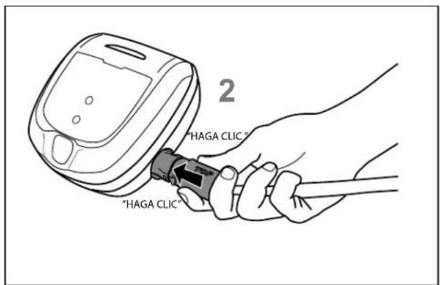
text_image
"HAGA CLIC" "HAGA CLIC"natural_image
Illustration of a hand inserting a plug into a device (no text or symbols present)natural_image
Illustration of hands operating a tracked robotic device with a curved handle, no text or symbols present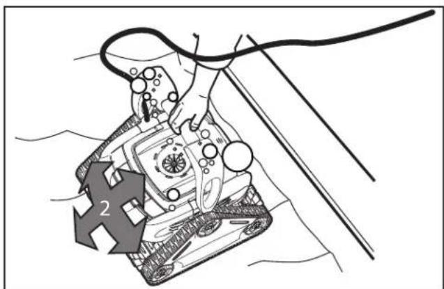
natural_image
Illustration of a tank with a rope and directional arrow, no text or symbols presenttext_image
Diagram showing a robotic device with two upward arrows labeled 1 and 2, indicating movement or operation in water.natural_image
Line drawing of a person using a robotic device to clean water, with a numbered callout indicating step 3 (no text or symbols on the diagram itself)natural_image
Line drawing of a tracked robot with a labeled component (no text or symbols present)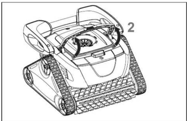
natural_image
Line drawing of a tracked robotic vehicle with visible tracks and wheels (no text or symbols)Figura 16. Libere la manija del cartucho del filtro
natural_image
Technical line drawing of a mobile robot with visible wheels and a central hub (no text or symbols)natural_image
Technical line drawing of a vehicle front panel with internal compartments and directional arrows indicating flow (no text or symbols)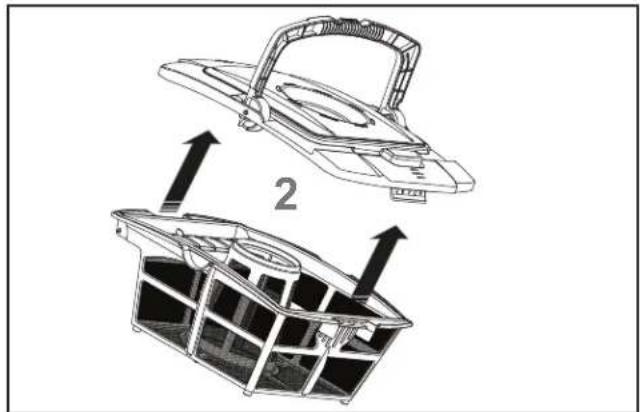
natural_image
Technical line drawing of a mechanical device with two views: top shows top view, bottom shows side view (no text or symbols)Figura 18. Retire la tapa del cartucho del filtro
natural_image
Line drawing of a hand using a tool to lift a component into a cooling fan (no text or symbols)natural_image
Line drawing of a person using a handheld device to connect cables, with no visible text or symbolsnatural_image
Line drawing of a lawn mower with adjustable wheels and a mounted head (no text or symbols)natural_image
Line drawing of a person using a cable to connect a device on a wall (no text or symbols)natural_image
Illustration of a hand using a tool to adjust or install a mechanical component, with no visible text or symbols.natural_image
Technical line drawing of a mechanical device with gears and housing (no text or symbols)natural_image
Illustration of hands holding a device with a grid pattern and directional arrow (no text or symbols)natural_image
Technical illustration of a mechanical assembly with no visible text or symbolsnatural_image
Line drawing of hands using scissors to cut a mechanical component (no text or symbols)natural_image
Technical line drawing of a mechanical component with no visible text or symbolstext_image
Diagram illustrating airflow or traffic flow around a vehicle, with arrows indicating direction and components.natural_image
Technical line drawing of a mechanical gear assembly with no visible text or symbolstext_image
Diagram of a mechanical conveyor belt system with labeled components and motion arrowsZodiac Pool Systems, Inc.
2620 Commerce Way, Vista, CA 92081
1.800.822.7933 | www.ZodiacPoolSystems.com
Zodiac Pool Systems Canada, Inc.
2115 South Service Road West, Unit 3
Oakville, Ontario • Canada L6L 5W2
1.888.647.4004 | www.ZodiacPoolSystems.ca
POLARIS® and the Polaris 3-wheeled cleaner design are registered trademarks of Zodiac Pool Systems, Inc.
ZODIAC ^® is a registered trademark of Zodiac International, S.A.S.U., used under license.
All other trademarks referenced herein are the property of their respective owners.
©2016 Zodiac Pool Systems, Inc. H0429900 Rev F