
THP2400A1050 - Thermostat HONEYWELL - Free user manual and instructions
Find the device manual for free THP2400A1050 HONEYWELL in PDF.
Download the instructions for your Thermostat in PDF format for free! Find your manual THP2400A1050 - HONEYWELL and take your electronic device back in hand. On this page are published all the documents necessary for the use of your device. THP2400A1050 by HONEYWELL.
USER MANUAL THP2400A1050 HONEYWELL
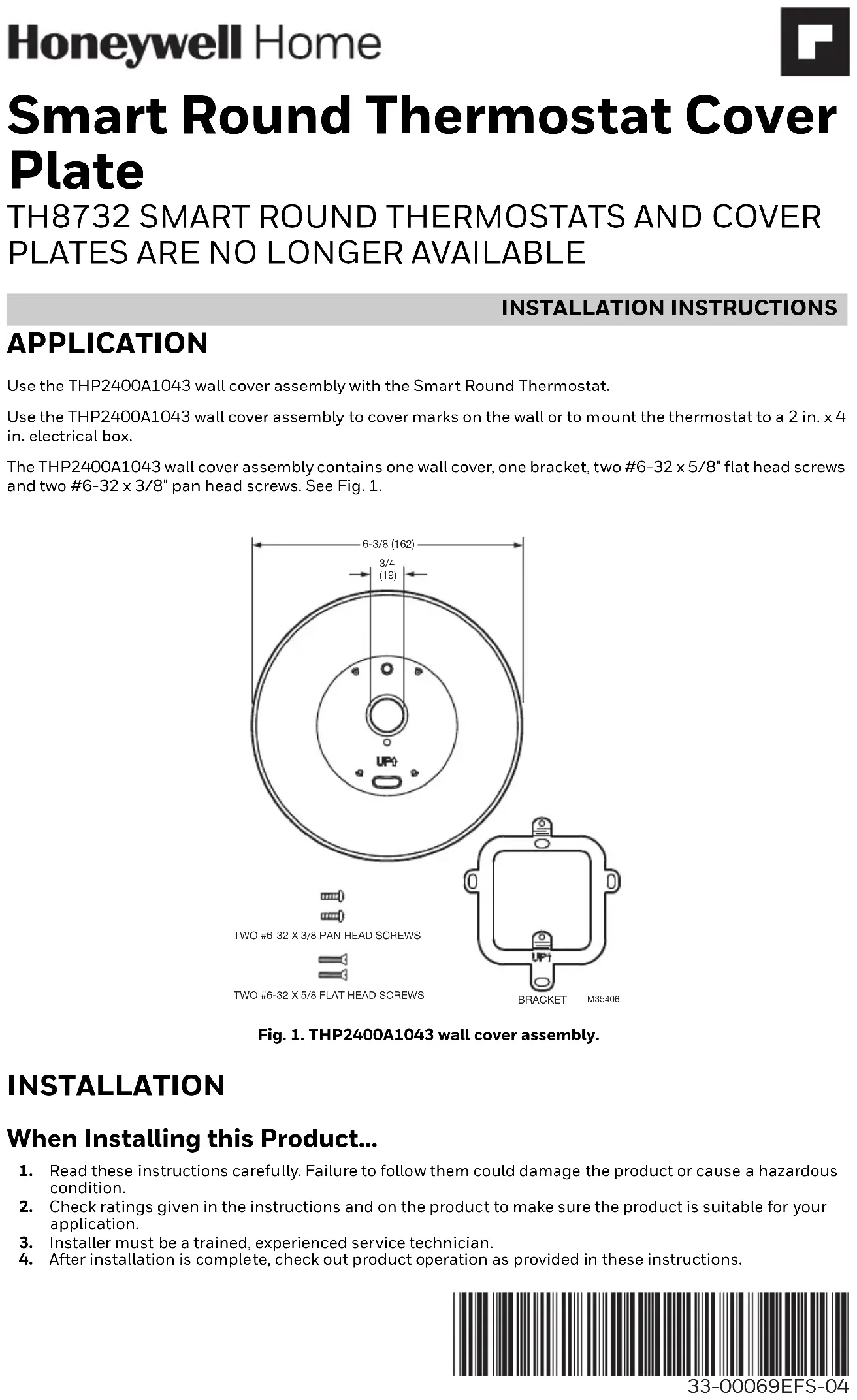
APPLICATION Use the THP2400A1043 wall cover assembly with the Smart Round Thermostat. Use the THP2400A1043 wall cover assembly to cover marks on the wall or to mount the thermostat to a 2 in. x 4 in. electrical box. The THP2400A1043 wall cover assembly contains one wall cover, one bracket, two #6-32 x 5/8" flat head screws and two #6-32 x 3/8" pan head screws. See Fig. 1.Fig. 1. THP2400A1043 wall cover assembly. INSTALLATION When Installing this Product…
1. Read these instructions carefully. Failure to follow them could damage the product or cause a hazardous
2. Check ratings given in the instructions and on the product to make sure the product is suitable for your
3. Installer must be a trained, experienced service technician.
4. After installation is complete, check out product operation as provided in these instructions.
TWO #6-32 X 5/8 FLAT HEAD SCREWS TWO #6-32 X 3/8 PAN HEAD SCREWS BRACKET6-3/8 (162) 3/4 (19)
M35406SMART ROUND THERMOSTAT COVER PLATE
33-00069EFS—04 2 CAUTION Electrical Hazard. Can cause electrical shock or equipment damage. Disconnect power before beginning installation. Mount Wall Cover Mount Wall Cover Directly to Wall (See Fig. 2)
1. Pull the wires through the wire hole on the wall cover.
2. Position the wall cover on the wall with the arrow pointing up. Check that the wall cover is leveled (for
3. Use a pencil to mark the mounting holes.
4. Remove the wall cover from the wall and proceed as follow:
- For drywall: Drill two 3/16-in. holes in the wall as marked. Tap the wall anchors (provided with the thermostat) into the holes, until the anchor collar touches the wall.
- For harder surface such as plaster: Drill two 7/32-in. holes in the wall as marked. Tap the wall anchors (provided with the thermostat) into the holes, until the anchor collar touches the wall.
5. Position the wall plate on the wall cover using the 4 mounting posts and snap them together.
6. Pull the wires through the wire hole on the wall cover / wall plate assembly. Position the assembly on the
7. Insert the mounting screws (provided with the thermostat) into the wall anchors. Check leveling, if desired,
and tighten the mounting screws. Fig. 2. Mount wall cover, wall plate and thermostat directly to wall.
MOUNTING SCREWS (2)(PROVIDED WITH THERMOSTAT) M35407
WIRE HOLEWALL COVERMOUNTING HOLES (2)THERMOSTATWIRE HOLEWALL PLATEMOUNTING HOLES (2) WALL OPENINGWALL ANCHORS (2)(PROVIDED WITH THERMOSTAT)DRILLEDHOLES (2) WALL WIRE AUX O/B
1. Position the bracket on the electrical box with the arrow pointing up. Insert two #6-32 X 5/8" flat head
screws. Level the bracket and tighten the flat head screws.
2. Position the wall plate on the wall cover using the 4 mounting posts and snap them together.
3. Pull the wires through the wire hole on the wall cover / wall plate assembly. Position the assembly on the
4. Insert two #6-32 X 3/8" pan head screws. Check leveling, if desired, and tighten the pan head screws.
Fig. 3. Mount bracket, wall cover, wall plate and thermostat to a vertical 2 in. x 4 in. electrical box.
WIRE HOLE MOUNTING HOLES (2) THERMOSTAT WIRE HOLE WALL PLATE MOUNTING HOLES (2) WIRE AUX O/B
MOUNTING POSTS (4) WALL
1. Position the bracket on the electrical box with the arrow pointing up. Insert two #6-32 X 5/8" flat head
screws. Level the bracket and tighten the flat head screws.
2. Position the wall plate on the wall cover using the 4 mounting posts and snap them together.
3. Pull the wires through the wire hole on the wall cover / wall plate assembly. Position the assembly on the
4. Insert two #6-32 X 3/8" pan head screws. Check leveling, if desired, and tighten the pan head screws.
Fig. 4. Mount bracket, wall cover, wall plate and thermostat to a horizontal 2 in. x 4 in. electrical box.
WIRE HOLE MOUNTING HOLES (2) THERMOSTAT WIRE HOLE WALL PLATE MOUNTING HOLES (2) WIRE AUX O/B
ANCRAGES (2) (FOURNIS AVEC LE THERMOSTAT)