
DXH40FA - Heating DEWALT - Free user manual and instructions
Find the device manual for free DXH40FA DEWALT in PDF.
| Product type | Laser distance meter |
| Brand | DeWalt |
| Model | DXH40FA |
| Measurement range | 6 in to 330 ft (0.15 m to 100 m) |
| Accuracy | Up to 10 m: ±1.5 mm; 10 to 30 m: ±0.15 mm/m; >30 m: ±0.2 mm/m |
| Resolution | 1/16 in (1 mm) |
| Laser type | Class 2 (≤1 mW) or Class 3R (≤5 mW) at 620-690 nm |
| Power supply | 3 AAA batteries (1.5 V) |
| Battery life | Up to 3000 measurements (2500 with Bluetooth) |
| Dimensions (H × D × W) | 120 × 48.5 × 26 mm |
| Weight (with batteries) | 280 g |
| Operating temperature | 0 °C to +40 °C |
| Storage temperature | -10 °C to +60 °C |
| Measurement functions | Distance, area, volume, Pythagoras (1 and 2 points), continuous measurement, addition/subtraction, angle measurement, level, memory (last 20 measurements) |
| Connectivity (models DW0165S/DW0330SN) | Bluetooth® compatible with DEWALT® Tool Connect™ app |
| Laser auto-off | 30 seconds |
| Device auto-off | Default 90 s, adjustable from 30 s to 300 s or can be disabled |
| Warranty | 3-year limited warranty, 1 year free service, 90-day money-back guarantee |
Frequently Asked Questions - DXH40FA DEWALT
User questions about DXH40FA DEWALT
0 question about this device. Answer the ones you know or ask your own.
Ask a new question about this device
Download the instructions for your Heating in PDF format for free! Find your manual DXH40FA - DEWALT and take your electronic device back in hand. On this page are published all the documents necessary for the use of your device. DXH40FA by DEWALT.
USER MANUAL DXH40FA DEWALT
DW0165N, DW0165S, DW0330SN User Manual
Figures
B
D
flowchart
graph TD
    A["1: 0.0000 m"] --> B["2: 50.0°"]
    B --> C["3: Sensor icon with icons"]
    C --> D["4: System icon with icons"]
    D --> E["5: Display icon with DW0165S/DW0330SN"]
    E --> F["6: System icon with ground symbol"]
    F --> G["7: Display icon with foot/m/s/electrical icons"]
Figures
H
flowchart
graph LR
    A["输入数据"] --> B["处理"]
    B --> C["输出结果"]
    style A fill:#f9f,stroke:#333
    style C fill:#bbf,stroke:#333
2
I
flowchart
graph LR
    A["1: Input Data"] --> B["2: Output Data"]
    style A fill:#f9f,stroke:#333
    style B fill:#bbf,stroke:#333
3
J
3
K
1
natural_image
Diagram of a conical object emitting beams into a rectangular block (no text or symbols)2
L
natural_image
Simple line drawing of a 3D rectangular prism with an arrow indicating horizontal direction (no text or symbols)1
3
M
2
natural_image
Simple line drawing of a 3D rectangular prism with an arrow indicating horizontal direction (no text or symbols)3
N
4
0
2
natural_image
Simple line drawing of a rectangular prism with directional arrows indicating depth (no text or symbols)3
Figures
Q
natural_image
Diagram showing a vehicle moving toward a vertical wall with dashed and dotted lines indicating direction (no text or symbols)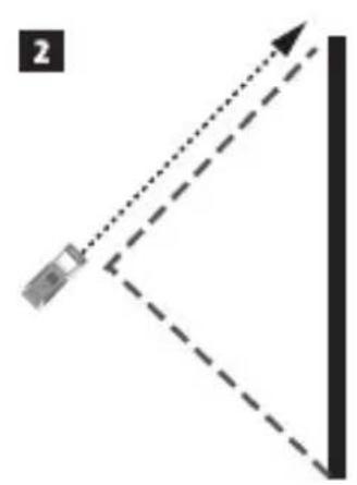
natural_image
Diagram showing a device positioned at an angle with dashed lines indicating direction (no text or symbols)
R
1
natural_image
Simple line diagram showing a pendulum and object at an angle with dashed lines indicating direction (no text or symbols)2
natural_image
Simple diagram showing a dashed arrow pointing to a rectangular box, with no text or symbols present.3
natural_image
Simple diagram showing a horizontal line with a dashed arrow pointing to a vertical rectangle and a solid square, no text or symbols present.4
S
2
T
1
2
natural_image
Simple diagram showing a surveying instrument on a tripod with a dashed diagonal line extending from the right (no text or symbols)3
natural_image
Diagram showing a surveying instrument with multiple dashed lines extending from it, no text or symbols present4
Figures

V
natural_image
Simple line drawing of a refrigerator with a button and side panel (no text or symbols)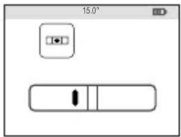
W
1

natural_image
Simple icon showing a document with a question mark and a diagonal line, no text or symbols present.2
X

1
natural_image
Simple line drawing of a rectangular box placed on a flat base (no text or symbols)2
3
4
5
E
Contents
- User Safety
- Battery Safety
- Loading Batteries
- Turning the Tool On
- Choosing the Settings
• Taking Measurements - Calibrating the Tool
- Warranty
- Error Codes
- Specifications
Retain all sections of this manual for future reference.
User Safety

WARNING:
Carefully read the Safety Instructions and Product Manual before using this product. The person responsible for the product must ensure that all users understand and adhere to these instructions.

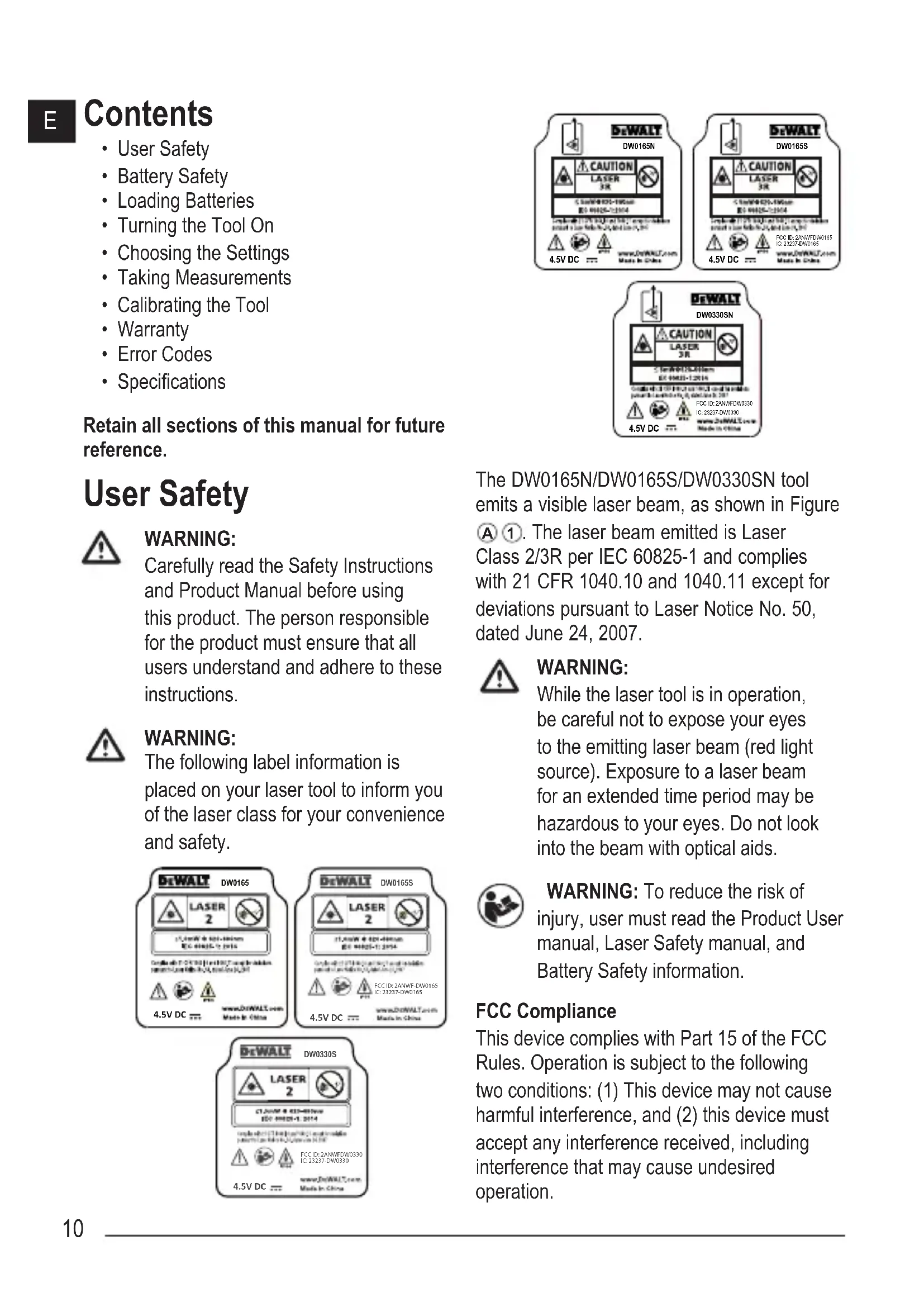
WARNING:
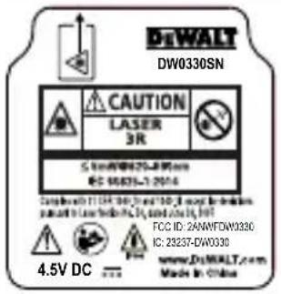
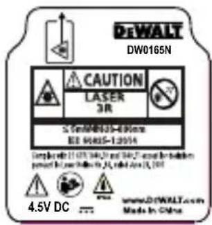
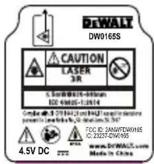
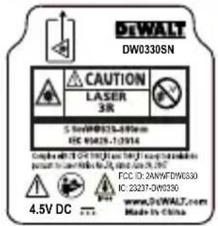
The following label information is placed on your laser tool to inform you of the laser class for your convenience and safety.
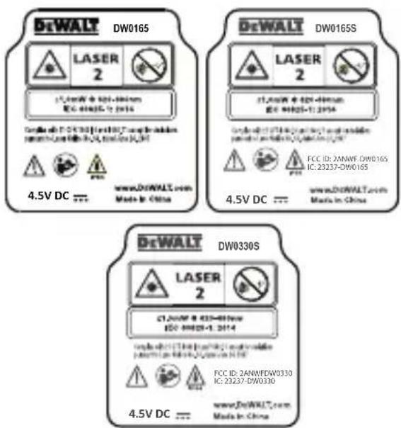
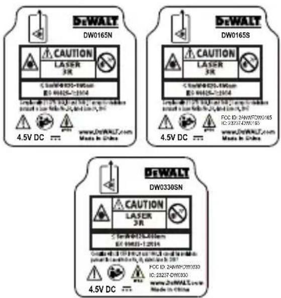
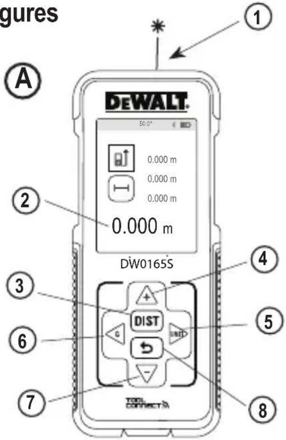
The DW0165N/DW0165S/DW0330SN tool emits a visible laser beam, as shown in Figure A ①. The laser beam emitted is Laser Class 2/3R per IEC 60825-1 and complies with 21 CFR 1040.10 and 1040.11 except for deviations pursuant to Laser Notice No. 50, dated June 24, 2007.

WARNING:
While the laser tool is in operation, be careful not to expose your eyes to the emitting laser beam (red light source). Exposure to a laser beam for an extended time period may be hazardous to your eyes. Do not look into the beam with optical aids.

WARNING: To reduce the risk of injury, user must read the Product User manual, Laser Safety manual, and Battery Safety information.
FCC Compliance
This device complies with Part 15 of the FCC Rules. Operation is subject to the following two conditions: (1) This device may not cause harmful interference, and (2) this device must accept any interference received, including interference that may cause undesired operation.
FCC Statement
This equipment has been tested and found to comply with the limits for a Class B digital device, pursuant to part 15 of the FCC rules. These limits are designed to provide reasonable protection against harmful interference in a residential installation. This equipment generates, uses, and can radiate radio frequency energy and, if not installed and used in accordance with the instructions, may cause harmful interference to radio communications. This device is a portable unit. The exclusion threshold is 0.887<3. However, there is no guarantee that interference will not occur in a particular installation. If this equipment does cause harmful interference to radio or television reception, which can be determined by turning the equipment off and on, the user is encouraged to try to correct the interference by one or more of the following measures:
- Reorient or relocate the receiving antenna.
- Increase the separation between the equipment and the receiver.
- Connect the equipment into an outlet on a different circuit (not the circuit to which the receiver is connected).
- Consult the dealer or an experienced radio/TV technician for help.
Canada, Industry Canada (IC) Notices
Class B digital circuitry of this device complies with Canadian ICES-003. This device complies with Industry Canada license-exempt RSS standard(s). Operation is subject to the following two conditions: (1) this device may not cause interference, and (2) this device must accept any interference, including interference that may cause undesired operation of the device. Under Industry Canada regulations, the radio transmitter(s) in this device may only operate using an antenna of a type and maximum (or lesser) gain approved for the transmitter by Industry Canada. To reduce potential radio interference to other users, the antenna type and its gain should be so chosen that the equivalent isotropically radiated power (e.i.r.p.) is not more than that necessary for successful communication.
Battery Safety

WARNING: Batteries can explode or leak and cause serious injury or fire. To reduce the risk:
ALWAYS follow all instructions and warnings on the battery label and package.
DO NOT short any battery terminals.
DO NOT charge alkaline batteries.
DO NOT mix old and new batteries. Replace all of them at the same time with new batteries of the same brand and type.
DO NOT mix battery chemistries.
DO NOT dispose of batteries in fire.
ALWAYS keep batteries out of reach of children.
ALWAYS remove batteries if the device will not be used for several months.
NOTE: Ensure that the recommended batteries are used.
NOTE: Ensure the batteries are inserted in the correct manner, with the correct polarity.
E
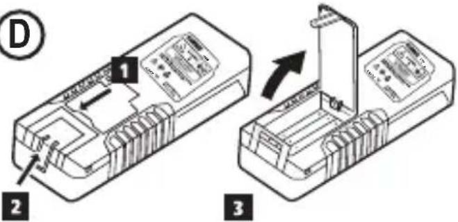
Loading Batteries
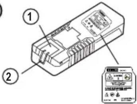
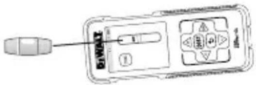
- Pull up the endpiece on the back of the tool (Figure D ①).
- Pull up the battery compartment latch on the back of the tool (Figure ① and ② and ③).
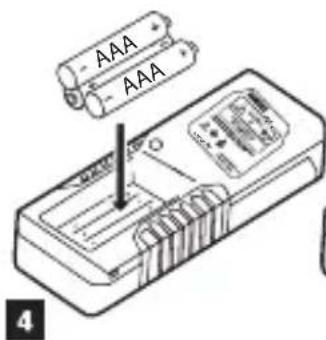
- Insert three AAA batteries, making sure to position the - and + ends of each battery as noted inside the battery compartment (Figure D 4).
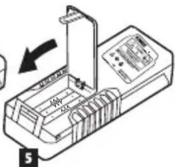
- Push the battery door down until it snaps in place (Figure D 5).
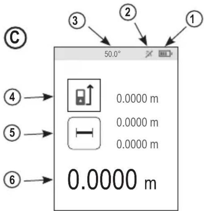
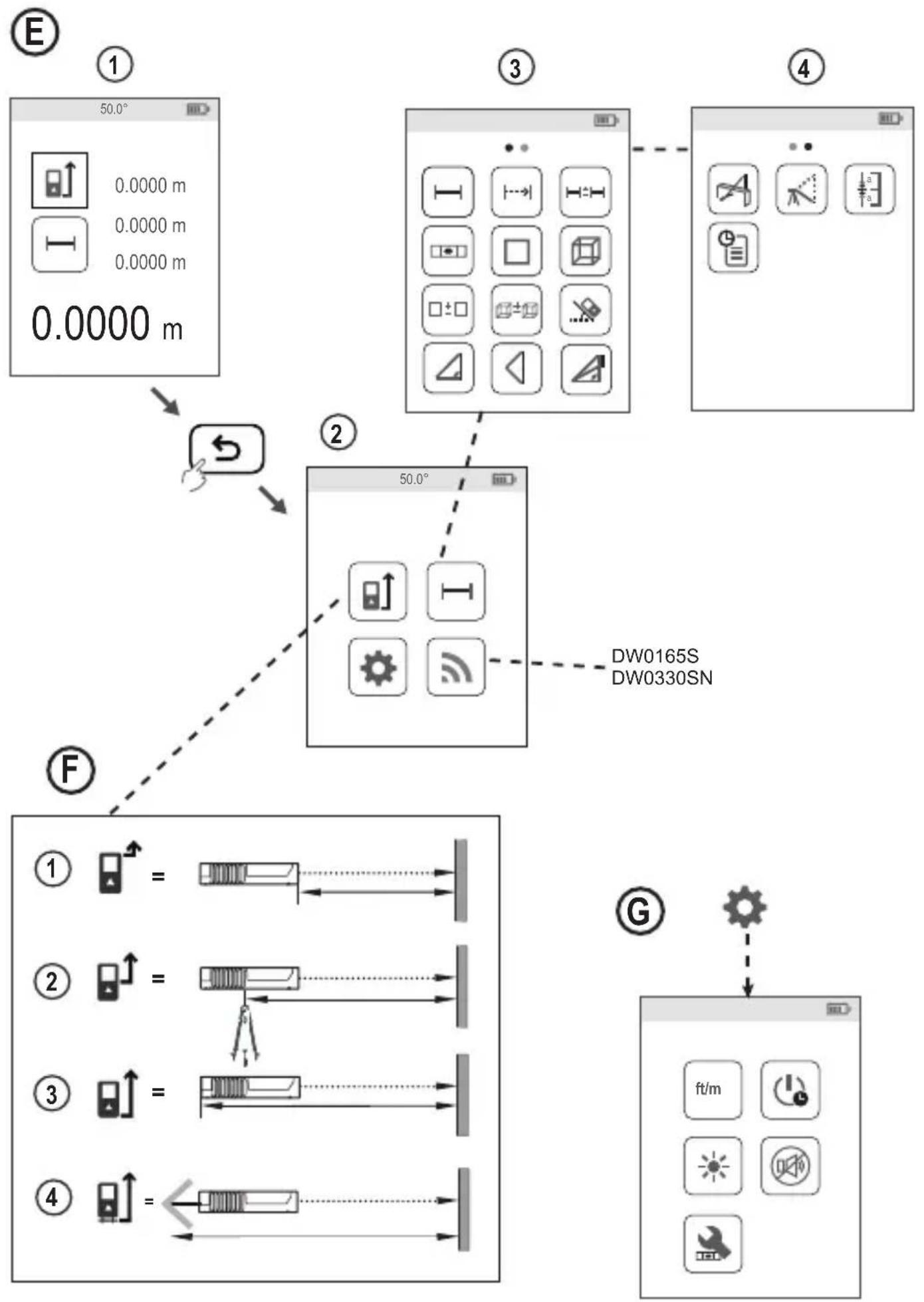
When the tool is ON, the battery level appears on the screen (Figure ①).
Turning the Tool On
- Point the tool's laser (Figure A 1) toward a wall or object, and not toward anyone's eyes.
- Press (Figure A 3) to turn the tool on and display the red laser dot.
Choosing the Settings
Setting Automatic Turn Off
By default, the tool will automatically turn off 90 seconds after no buttons or options have been selected. To change when the tool automatically turns off, follow these steps.
- On the first screen (Figure E ①), press to display the Main Menu.
- On the Main Menu (Figure E ②), select ⚙️ and press OBST
-
On the Settings Menu (Figure G), select and press .DIST
-
Select the time.
-
Choose to turn off the tool after 30 sec, 60 secs, 90 secs, or 300 secs.
-
To keep the tool turned on until you manually turn it off (by pressing and holding for 10 seconds), select
-
Press to save your setting.
Setting Screen Brightness

By default, the tool's screen will be set at 25% brightness. To change the brightness level, follow these steps.
- On the first screen (Figure E 1), press to display the Main Menu.
- On the Main Menu (Figure ②), select ⚙ and press .DIST
- On the Settings Menu (Figure G), select and press DIST
- Select the desired brightness level: 25%, 50%, 75%, or 100%.
- Press to save your new setting.
Turning Off the Sound
By default, the tool will beep each time you take a measurement. You can turn off the beeps.
- On the first screen (Figure E 1), press → to display the Main Menu.
- On the Main Menu (Figure Ⓔ 2), select ⚙ and press . Dist
- On the Settings Menu (Figure G), select and press to display .
- Press to save your setting.
Changing the Unit of Measure ft/m
By default, the tool will display measurements in inches (74 9/16 in). You can change the unit of measure to fractional ft (6'02"9/16), meters (1.8940 m), decimal ft (6.21 ft), or decimal inches (3.21 in).
- On the first screen (Figure ①), press to display the Main Menu.
- On the Main Menu (Figure E ②), select ⚙ and press .DIST
- On the Settings Menu (Figure G), select ft/m and press .DIST
- Select the unit of measure.
• 0'00" 0/00
• 0" 0/00
- 0'00" ft
• 0.00 in
• 0.0000 m
- Press to save your setting.
Choosing the Tool Position
By default, distances are measured from the bottom of the tool to a wall or object (Figure F ③). To measure distances from a different tool location, follow these steps.
- On the first screen (Figure ①), press to display the Main Menu.
- On the Main Menu (Figure ⑤②), select and press DIST
-
Select the tool position.
-
To measure from the top of the tool (Figure F 1), select
- To measure from the tripod connection on the tool (Figure ⑤ ②), select
- To measure from a corner or another hard-to-reach location with the endpiece flipped open (Figure D 1), select at (Figure F 4) to measure from the end of the endpiece.
- Press to save your new setting.
Taking Measurements
Measuring Distance
- Point the tool's laser (Figure A ①) toward a wall or object, and not toward anyone's eyes.
- Press (Figure A 3) to turn the tool on and display the red laser dot.
- Make sure the tool position setting (Figure C 4) is correct for taking the measurement.
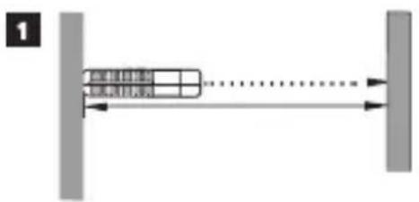
- Point the tool's laser (Figure A 1) toward the wall or object whose distance you need to measure (Figure H 1).
- Press to measure the distance from the tool to the wall or object.
- At the bottom of the screen, view the current measurement (Figure H ②).
To take a new measurement, press DIST to move the current measurement up to the previous line on the screen. Then repeat steps 4-6.
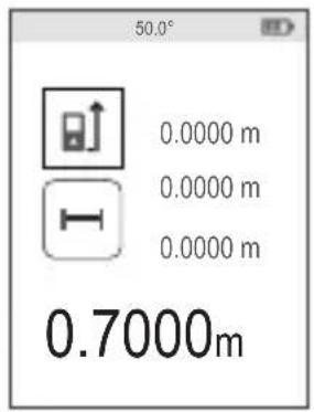
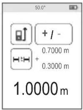
Adding 2 Measurements H:H
You can add two measurements to get a total measurement of the two distances (Figure 1).
- Point the tool's laser (Figure A 1) toward a wall or object, and not toward anyone's eyes.
E
- Press (Figure A 3) to turn the tool on and display the red laser dot.
- Make sure the tool position setting (Figure C 4) is correct for taking the measurement.
-
Select as the measurement type.
-
Press to display the Main Menu (Figure E 2)
- Press to select.
- Press to display the Measurement Type Menu (Figure E 3).
- Press the arrow buttons to select H≡H
-
Press .DIST
-
Press to indicate that you want to add two measurements.
- Point the tool's laser toward the wall or object whose distance you need to measure (Figure ① ①).
- Press to measure the distance from the tool to the first wall or object.
- Point the tool's laser toward the next wall or object (Figure ① ②).
- Press to measure the distance and add it to the previous measurement.
- View the total of the two measurements at the bottom of the screen (Figure ① ③).
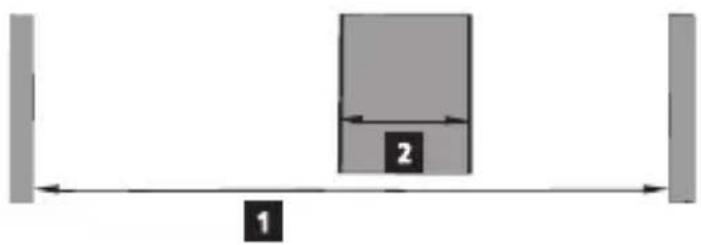
Subtracting 2 Measurements H:H
You can subtract one measurement from another (Figure Ⓙ).
- Point the tool's laser (Figure A 1) toward a wall or object, and not toward anyone's eyes.
-
Press (Figure A 3) to turn the tool on and display the red laser dot.
-
Make sure the tool position setting (Figure C 4) is correct for taking the measurement.
-
Select as the measurement type.
-
Press to display the Main Menu (Figure ①②).
- Press to select.
- Press to display the Measurement Type Menu (Figure E 3).
- Press the arrow buttons to select H≡H
-
Press .DIST
-
Press to indicate that you want to subtract one measurement from another.
- Point the tool's laser toward the wall or object whose distance you need to measure (Figure J 1).
- Press to measure the distance from the tool to the wall or object.
- Point the tool's laser toward the wall or object whose distance is to be subtracted from the first measurement (Figure J 2).
- Press to measure the distance and subtract it from the previous measurement.
- View the difference between the two measurements at the bottom of the screen (Figure ① ③).
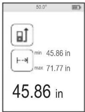
Measuring Continuously |…|
To take a series of measurements as you move around, change to Continuous Measure mode (Figure ).
- Point the tool's laser (Figure A 1) toward a wall or object, and not toward anyone's eyes.
-
Press Figure A 3) to turn the tool on and display the red laser dot.
-
Make sure the tool position setting (Figure ⑤④) is correct for taking the measurement.
-
Select has the measurement type.
- Press to display the Main Menu (Figure ⑤ ②).
- Press ▶ to select .
- Press to display the Measurement Type Menu (Figure E 3).
- Press the arrow buttons to select :--
- Press .DIST
-
Point the tool's laser (Figure A 1) toward the wall or object whose distance you need to measure (Figure K 1).
-
At the bottom of the screen, view the current measurement (Figure ①②), which will keep changing as you move the tool.
-
To take the current measurement (from the tool to the wall or object) and exit Continuous Measure mode, press .DIST
To take a new measurement, press DIST to move the current measurement up to the previous line on the screen. Then repeat steps 4-7.
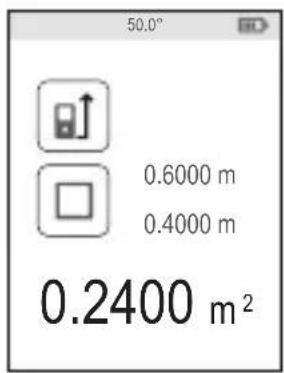
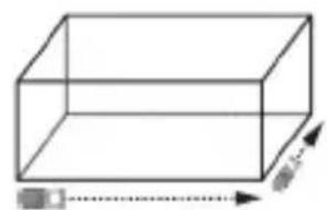
Measuring Area □
You can measure the area of a wall, floor, or object (Figure L).
-
Point the tool's laser (Figure A①) toward a wall or object, and not toward anyone's eyes.
-
Press (Figure A 3) to turn the tool on and display the red laser dot.
-
Make sure the tool position setting (Figure ①④) is correct for taking the measurement.
-
Select as the measurement type.
- Press to display the Main Menu (Figure E 2).
- Press to select.
- Press to display the Measurement Type Menu (Figure E 3).
- Press the arrow buttons to select □
- Press .DIST
- Measure the width (Figure ①).
- Point the top of the tool at one side of the wall, floor, or object.
- Position the tool at one end of the wall, floor, or object and point the laser dot across the width. (Figure ① shows where to position the tool if you are measuring from the bottom of the tool.)
- Press to display the width measurement at the top of the screen.
- Measure the length (Figure ⑤②).
- Position the tool at one end of the wall, floor, or object and point the laser dot across the length. (Figure ①② shows where to position the tool if you are measuring from the bottom of the tool.)
- Press to display the length measurement on the second line of the screen.
- View the Area measurement at the bottom of the screen (Figure ⑤ ③).
E
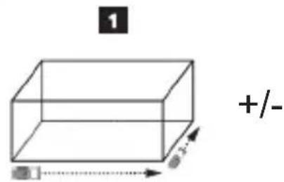
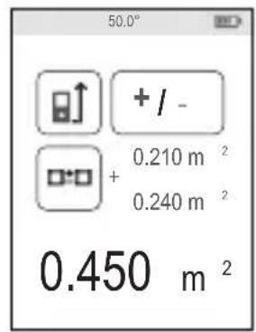
Adding/Subtracting 2 Areas

You can measure the area of a wall, floor, or object and then add it to, or subtract it from, the area of another wall, floor, or object (Figure M).
- Point the tool's laser (Figure A ①) toward a wall or object, and not toward anyone's eyes.
- Press (Figure A 3) to turn the tool on and display the red laser dot.
- Make sure the tool position setting (Figure ⑤④) is correct for taking the measurement.
-
Select as the measurement type.
-
Press to display the Main Menu (Figure E 2).
- Press to select.
- Press to display the Measurement Type Menu (Figure E 3).
- Press the arrow buttons to select ☐:☐
-
Press .DIST
-
Press △ to add, or ▽ to subtract, the areas of two walls, floors, or objects.
-
Measure the width of the first wall, floor, or object (Figure D 1).
-
Position the tool at one end of the wall, floor, or object and point the laser dot across the width. (Figure M 1 shows where to position the tool if you are measuring from the bottom of the tool.)
-
Press to display the width measurement at the top of the screen.
-
Measure the length of the first wall, floor, or object (Figure M 2).
-
Position the tool at one end of the wall, floor, or object and point the laser dot across the length. (Figure M 2 shows where to position the tool if you are measuring from the bottom of the tool.)
-
Press to display the length measurement on the second line of the screen.
-
Follow the same steps to measure the width and length of the second wall, floor, or object.
- View the Area measurement at the bottom of the screen (Figure M 3).
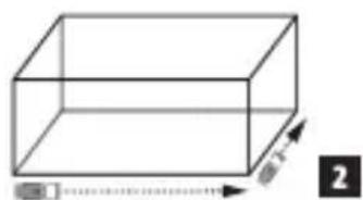
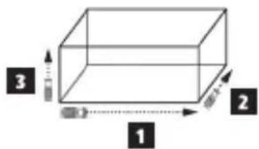
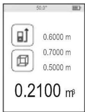
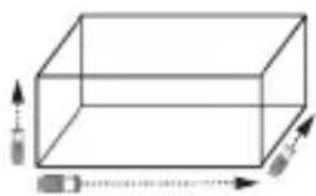
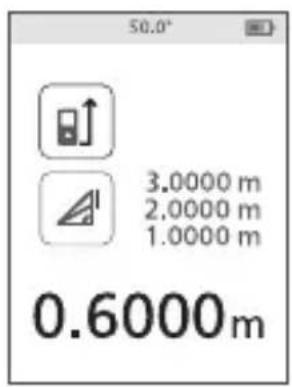
Measuring Volume

You can measure the volume of a room or object (Figure N).
- Point the tool's laser (Figure A 1) toward a wall or object, and not toward anyone's eyes.
- Press (Figure ③) to turn the tool on.
- Make sure the tool position setting (Figure C 4) is correct for taking the measurement.
-
Select as the measurement type.
-
Press to display the Main Menu (Figure E 2).
- Press to select.
- Press to display the Measurement Type Menu (Figure E 3).
- Press the arrow buttons to select
-
Press DIST
-
Measure the width (Figure N 1).
-
Point the top of the tool at one side of the target (room or object).
- Position the tool at one end of the target and point the laser dot across the width. (Figure N 1 shows where to position the tool if you are measuring from the bottom of the tool.)
-
Press to display the width measurement at the top of the screen.
-
Measure the length (Figure N 2).
-
Position the tool at one end of the target and point the laser dot across the length. (Figure N 2 shows where to position the tool if you are measuring from the bottom of the tool.)
-
Press to display the length measurement on the second line of the screen.
-
Measure the height (Figure N 3).
-
Position the tool at one end of the target and point the laser dot across the height. (Figure N 3 shows where to position the tool if you are measuring from the bottom of the tool).
-
Press to display the height measurement on the third line of the screen.
-
View the Volume measurement at the bottom of the screen (Figure N ④).
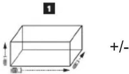
Adding/Subtracting 2 Volumes

You can measure the volume of room or object and then add it to, or subtract it from, the volume of another room or object (Figure ①).
- Point the tool's laser (Figure A 1) toward a wall or object, and not toward anyone's eyes.
- Press (Figure A 3) to turn the tool on and display the red laser dot.
- Make sure the tool position setting (Figure C 4) is correct for taking the measurement.
- Select as the measurement type.
- Press to display the Main Menu (Figure E 2).
- Press to select.
- Press to display the Measurement Type Menu (Figure E 3).
- Press the arrow buttons to select
- Press DIST
- Press ▲ to add, or ▼ to subtract, the volumes of two rooms or objects.
- Measure the width (Figure ①①).
- Position the tool at one end of the room or object and point the laser dot across the width. (Figure ① shows where to position the tool if you are measuring from the bottom of the tool.) - Press to display the width measurement at the top of the screen.
-
Measure the length (Figure ①②).
-
Position the tool at one end of the room or object and point the laser dot across the length. (Figure ① ② shows where to position the tool if you are measuring from the bottom of the tool.)
-
Press to display the length measurement on the second line of the screen.
-
Measure the height (Figure ① ③).
-
Position the tool at one end of the room or object and point the laser dot across the height. (Figure ① ③ shows where to position the tool if you are measuring from the bottom of the tool).
-
Press to display the height measurement on the third line of the screen.
-
Follow the same steps to measure the width, length, and height of the second room or object.
- View the Volume measurement at the bottom of the screen (Figure ①④).
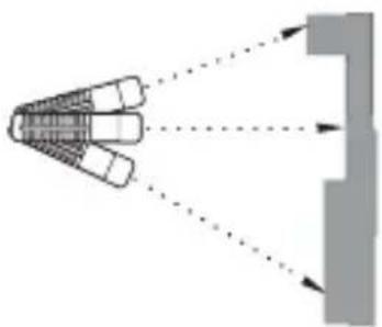
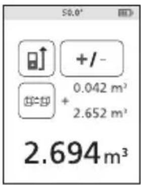
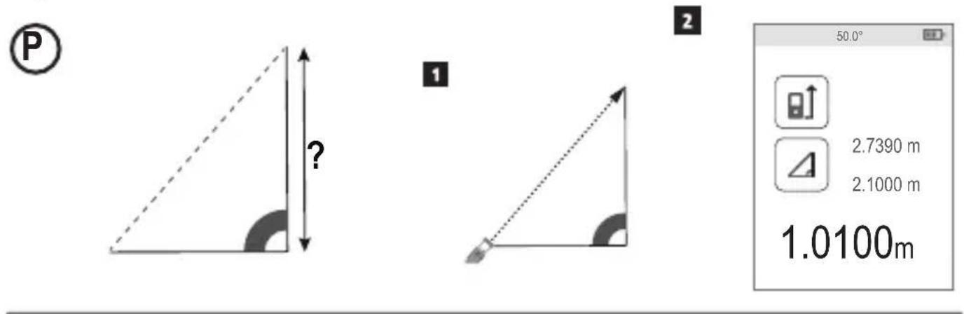
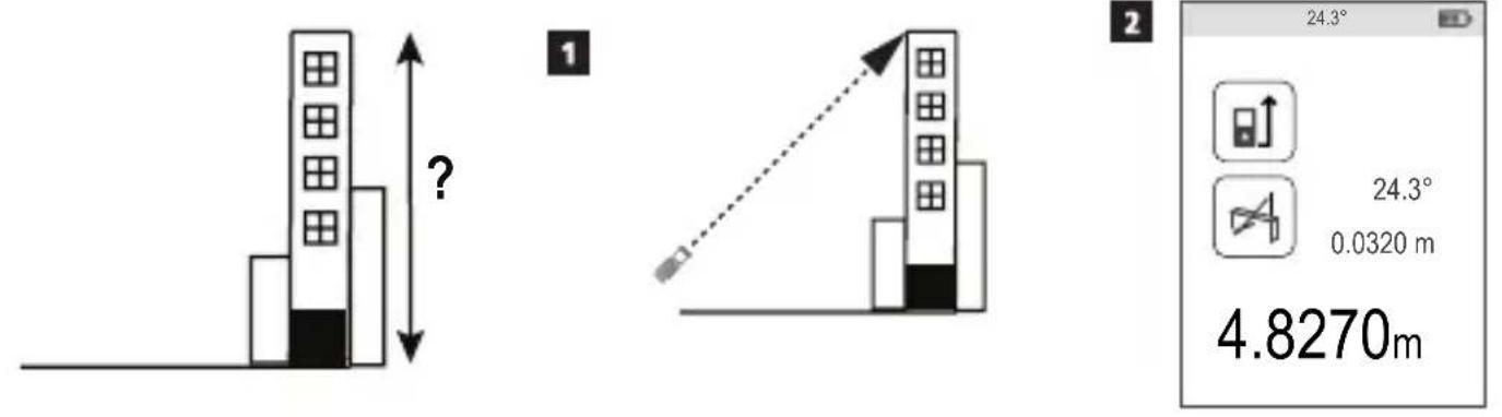
Measuring the Height of a Tall Object
If you need to measure the height of a tall object (e.g., a tall building), you can calculate the height based on the distance to 1 point or the distances from the same point to 2 points on the object. The tool will use the Pythagorean Theorem ( C^2=A^2+B^2 ) to calculate the height.
Distance to 1 Point
You can use the distance to one point on a wall or object (Indirect Height) to determine its height (Figure P).
- Point the tool's laser (Figure A 1) toward a wall or object, and not toward anyone's eyes.
- Press (Figure A 3) to turn the tool on and display the red laser dot.
-
Make sure the tool position setting (Figure C 4) is correct for taking the measurement.
-
Select as the measurement type.
-
Press to display the Main Menu (Figure E 2).
- Press to select.
- Press to display the Measurement Type Menu (Figure E 3).
- Press the arrow buttons to select ↙
-
Press .DIST
-
Position the tool opposite the bottom of the vertical height to be measured (Figure P ①).
- Point the laser toward the highest point of the building or object whose height you need to measure (Figure ①).
- Press to measure the distance.
- View the height measurement at the bottom of the screen (Figure P 2).
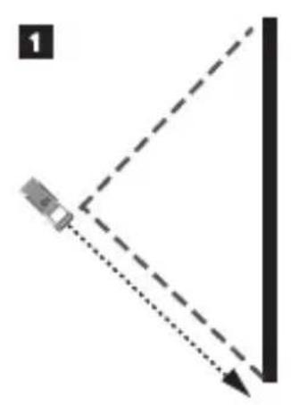
Distances to 2 Points
You can use the distance to two points on a wall or object (Double Indirect Height) to determine its height (Figure ①).
- Point the tool's laser (Figure A 1) toward a wall or object, and not toward anyone's eyes.
- Press (Figure A 3) to turn the tool on and display the red laser dot.
-
Make sure the tool position setting (Figure C 4) is correct for taking the measurement.
-
Select as the measurement type.
-
Press to display the Main Menu (Figure E 2).
- Press to select . H
- Press to display the Measurement Type Menu (Figure E 3).
- Press the arrow buttons to select .1
- Press .DIST
- Position the tool opposite the approximate center of the vertical height to be measured (Figure Q 1).
- Point the laser toward the lowest point of the building or object whose height you need to measure (Figure ②②).
- Press to measure the distance.
- From the same point, aim the laser at the highest point of the building or object (Figure Q 3).
- Press to measure the distance.
- On the bottom line of the screen, view the height of the building or object (Figure ④).
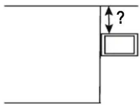
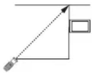
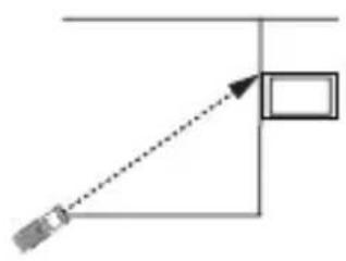
Measuring Partial Height of a Wall

If you need to determine the height of a section of a wall or object (e.g., the distance from the ceiling to the top of TV or window on the wall) (Figure R).
- Point the tool's laser (Figure A ①) toward a wall or object, and not toward anyone's eyes.
- Press (Figure A 3) to turn the tool on and display the red laser dot.
-
Make sure the tool position setting (Figure ①④) is correct for taking the measurement.
-
Select as the measurement type.
-
Press to display the Main Menu (Figure E 2).
- Press to select.
- Press to display the Measurement Type Menu (Figure E 3).
- Press the arrow buttons to select
-
Press .DIST
-
Point the laser at the highest point of the wall or object (Figure ⑧①).
- Press to measure the distance to the top of the tall object.
- From the same point, aim the laser at the top of the obstruction on the wall or object (Figure R 2).
- Press to measure the distance from the top of the wall to the obstruction (TV, window, etc.).
- From the same point, aim the laser on a horizontal line straight ahead toward the bottom of the wall (Figure ③).
- Press to measure the distance.
- On the bottom line of the screen, view the distance between the top of the wall and the top of the obstruction on the wall (Figure ④).
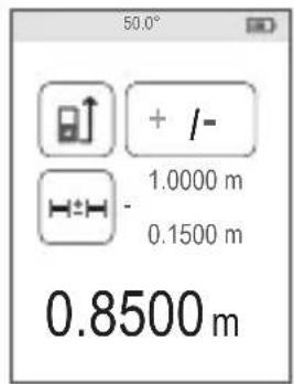
Measuring Height of Obstructed Object

Follow these steps to determine the height of a tall building or object that is blocked by other buildings or objects (Figure S).
- Point the tool's laser (Figure A ①) toward a wall or object, and not toward anyone's eyes.
- Press (Figure A 3) to turn the tool on and display the red laser dot.
E
-
Make sure the tool position setting (Figure C 4) is correct for taking the measurement.
-
Select as the measurement type.
- Press to display the Main Menu (Figure E 2).
- Press to select .
- Press to display the Measurement Type Menu (Figure E 3).
- Press the arrow buttons to select ⚠4 (Figure ⑤ ④).
- Press .DIST
-
Point the laser at the highest point of the building, wall, or object (Figure ⑤①).
-
Press to take the measurement.
-
On the bottom line of the screen, view the height of the building or object (Figure ⑤②).
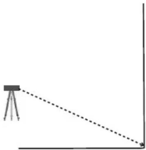
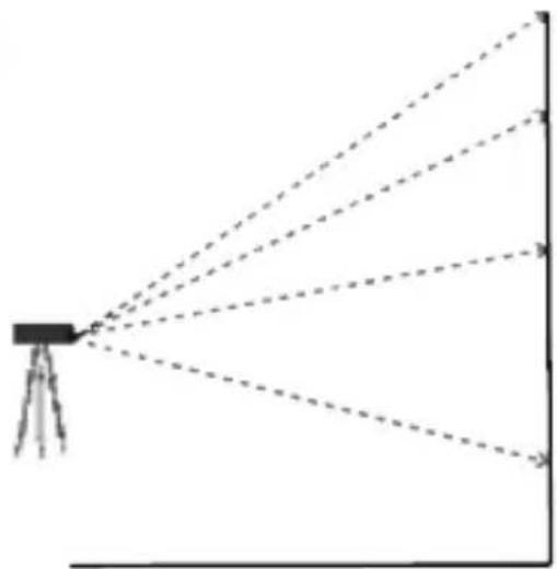
Measuring from a Tripod
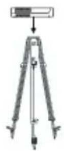
If you are placing the tool on a tripod to measure the height of a tall building, follow these steps (Figure T).
-
Screw the 1/4-20" hole on the back of the tool onto the 1/4-20" connection on the top of your tripod (Figure ①①).
-
Point the tool's laser (Figure A 1) toward a wall or object, and not toward anyone's eyes.
-
Press (Figure A 3) to turn the tool on and display the red laser dot.
-
Make sure the tool position setting (Figure C ④) is to measure from the tripod connection.
-
Select as the measurement type.
- Press to display the Main Menu (Figure E 2).
- Press to select.
- Press to display the Measurement Type Menu (Figure E 3).
- Press the arrow buttons to select ⚠️ (Figure ④).
- Press .DIST
-
Point the laser at the lowest point of the wall or object whose height you need to measure (Figure ⑦②).
-
Press to take the measurement.
-
Point the laser at other points on the wall or object (Figure ⑦ ③).
-
When ready, press to take the measurement.
-
On the bottom line of the screen, view the height of the wall or object (Figure T 4).
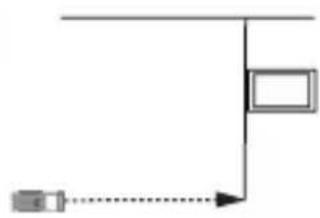
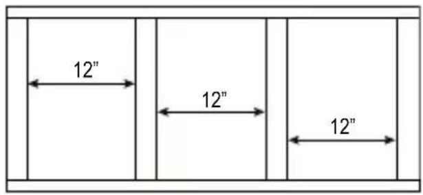
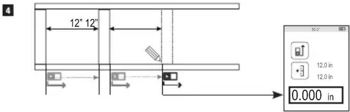
Positioning Studs
When you are framing a wall, use the Stakeout feature to easily mark the position of each stud (Figure ①).
-
Point the tool's laser (Figure A ①) toward a wall or object, and not toward anyone's eyes.
-
Press (Figure A 3) to turn the tool on and display the red laser dot.
-
Make sure the tool position setting (Figure C ④) is set to to measure from the back of the tool.
-
Select as the measurement type.
- Press to display the Main Menu (Figure E 2).
- Press to select .
- Press to display the Measurement Type Menu (Figure E 3).
- Press the arrow buttons to select (Figure E 4).
- Press DIST
-
Determine the distance between each stud, for example, 12".
-
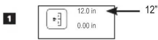
Press and until the top number on the screen is set to the distance from the right edge of one stud to the left edge of the next (e.g., 12") (Figure U 1).
-
Line up the back of the tool with the right edge of the last stud that is nailed in (Figure ①②).
-
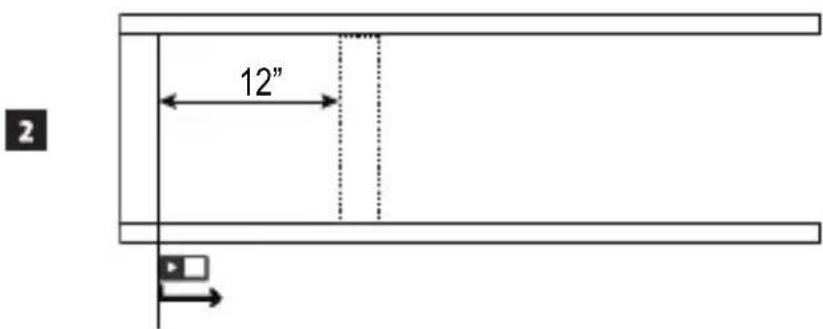
Press to start measuring the distance as you slowly move the tool to the right.
-
Continue moving the tool to the right until the bottom number on the screen is 0.00 in (Figure U 3).
-
Press to stop measuring.
-
Using a pencil, mark the location where the left edge of the stud should be nailed into the wall frame.
-
Nail the left edge of the stud at the marked location.
-
For each remaining stud in the wall frame, repeat steps 7-12 (Figure U 4).
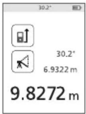
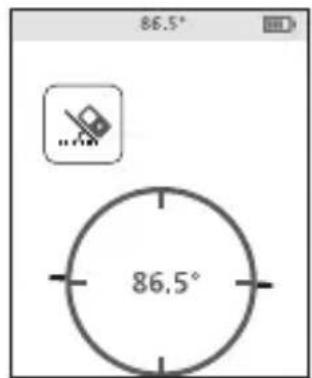
Measuring an Angle

If you need to determine the angle at which something is positioned, use the tool to measure that angle (Figure w).
- Point the tool's laser (Figure A ①) toward a wall or object, and not toward anyone's eyes.
- Press (Figure A 3) to turn the tool on and display the red laser dot.
- Make sure the tool position setting (Figure ①④) is correct for taking the measurement.
-
Select -as the measurement type.
-
Press to display the Main Menu (Figure E 2).
- Press to select.
- Press to display the Measurement Type Menu (Figure E 3).
- Press the arrow buttons to select
-
Press DIST
-
Position the tool at the angle to be measured (Figure ①).
- Press to take the measurement.
- View the angle measurement on the screen (Figure ⑦②).
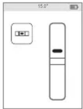
Using the Tool as a Level

- Point the tool's laser (Figure A 1) toward a wall or object, and not toward anyone's eyes.
-
Press (Figure A 3) to turn the tool on and display the red laser dot.
-
Select as the measurement type.
-
Press to display the Main Menu (Figure E 2).
- Press to select .
- Press to display the Measurement Type Menu (Figure E 3).
- Press the arrow buttons to select
-
Press .DIST
-
Place the tool in the vertical or horizontal position on the surface that you want to check is level (Figure V 1).
- On the tool's screen, view the position of the white bubble on the vial (Figure ⑤ ②).
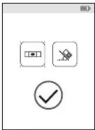
Using DW0165S/DW0330SN With

If you have a DW0165S or DW0330SN, you can use its Bluetooth® capability to pair it with the DEWALT® Tool Connect™ application on your cell phone or tablet, and then mark up room photos with the measurements you have taken.
- From either

download the DEWALT® Tool Connect™ application to your cell phone or tablet.
- Using the DEWALT® Tool Connect™ application, capture the room or space for which you want to record the measurements, by taking room photos.
-
On the DW0165S or DW0330SN keypad, press to turn on the tool.
-
If appears on the screen (Figure ②), turn on the Bluetooth® connection.
-
On the keypad, press to display the main menu.
- Select
-
Press to turn on the Bluetooth connection.
-
Use the DEWALT® Tool Connect™ application to pair your cell phone or tablet to the DW0165S or DW0330SN, and then mark up room photos with the measurements you have taken.
Bluetooth®
THE BLUETOOTH® WORD MARK AND LOGOS ARE REGISTERED TRADEMARKS OWNED BY BLUETOOTH SIG, INC. AND ANY USE OF SUCH MARKS BY DEWALT IS UNDER LICENSE. APPLE AND THE APPLE LOGO ARE TRADEMARKS OF APPLE INC., REGISTERED IN THE U.S. AND OTHER COUNTRIES. APP STORE IS A SERVICE MARK OF APPLE INC., REGISTERED IN THE U.S. AND OTHER COUNTRIES. GOOGLE PLAY AND THE GOOGLE PLAY LOGO ARE TRADEMARKS OF GOOGLE INC.
Viewing the Tool's Memory
Up to the last 20 measurements are stored in the tool's memory.
- Point the tool's laser (Figure A 1) toward a wall or object, and not toward anyone's eyes.
-
Press (Figure A 3) to turn the tool on and display the red laser dot.
-
Select as the measurement type.
-
Press to display the Main Menu (Figure E 2).
- Press to select .
- Press to display the Measurement Type Menu (Figure E 3).
- Press the arrow buttons to select 📄 (Figure E 4).
-
Press .DIST
-
View the last measurement that was taken. Press to scroll through all the measurements that have been stored in the tool's memory (up to 20). Press to scroll back.
Clearing the Tool's Memory
You can clear one or more measurements that are currently in the tool's memory.
Clearing a Measurement
- Point the tool's laser (Figure A ①) toward a wall or object, and not toward anyone's eyes.
- Press (Figure A 3) to turn the tool on and display the red laser dot.
-
Select as the measurement type.
-
Press to display the Main Menu (Figure E 2).
- Press to select.
- Press to display the Measurement Type Menu (Figure E 3).
- Press the arrow buttons to select 📋 (Figure ④).
-
Press .DIST
-
Specify which measurement you want to delete:
-
To delete a specific measurement, continue with step 5.
-
To delete ALL measurements, skip to step 6.
-
To delete a specific measurement:
-
Press or to scroll through the measurements that have been stored in the tool's memory (up to 20) until you display the measurement to be deleted.
- Press .
-
Select and press to delete the measurement.
-
To delete ALL measurements:
-
Press .
- Select and press to delete all measurements from the tool's memory.
Turning Off the Tool
The tool can be turned off in either of these ways:
- Press and hold for 10 seconds. When you release after 10 seconds, the tool will turn off.
- If you do not use the tool for 90 seconds, it will automatically turn off.
E
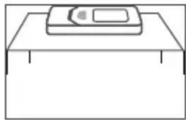
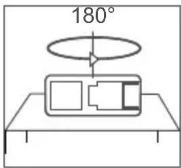
Calibrating the tool

Please note that if you do not position the tool correctly for each step of the calibration process, will appear in red on the screen (Figure X).
- Point the tool's laser (Figure A 1) toward a wall or object, and not toward anyone's eyes.
- Press (Figure A 3) to turn the tool on and display the red laser dot.
- Press to display the Main Menu (Figure E 2).
- On the Main Menu, select and press DIST.
- On the Settings Menu (Figure G), select and press .DIST
- Place the tool with the screen facing upward on a flat, level surface (Figure ⑧ ①).
- Press . DIST
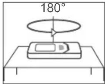
- While the tool is still laying on the level surface, turn the tool 180^ (Figure X 2).
- Press DIST
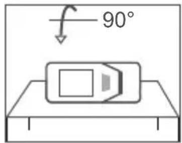
- Flip the long side of the tool 90^ so it is laying on its side (Figure X 3).
- Press DIST
- While the tool is still laying on its side, turn the tool 180^ (Figure X 4).
- Press DIST
- Make sure 🔒 appears on the tool's screen (Figure X 5).
Three Year Limited Warranty
DEWALT will repair, without charge, any defects due to faulty materials or workmanship for three years from the date of purchase. This warranty does not cover part failure due to normal wear or tool abuse. For further detail of warranty coverage and warranty repair information, visit www.DEWALT.com or call 1–800–4-DEWALT (1–800–433–9258). This warranty does not apply to accessories or damage caused where repairs have been made or attempted by others. This warranty gives you specific legal rights and you may have other rights which vary in certain states or provinces.
In addition to the warranty, DEWALT ^® tools are covered by our:
1 YEAR FREE SERVICE
DEWALT will maintain the tool and replace worn parts caused by normal use, for free, any time during the first year after purchase.
90 DAY MONEY BACK GUARANTEE
If you are not completely satisfied with the performance of your DEWALT Power Tool, Laser, or Nailer for any reason, you can return it within 90 days from the date of purchase with a receipt for a full refund - no questions asked.
RECONDITIONED PRODUCT:
Reconditioned product is covered under the 1 Year Free Service Warranty. The 90 Day Money Back Guarantee and the Three Year Limited Warranty do not apply to reconditioned product.
FREE WARNING LABEL REPLACEMENT:
If your warning labels become illegible or are missing, call 1-800-4-DEWALT or visit your local service center for a free replacement.
Error Codes
E
If INFO appears on the screen with a Code number, perform the corresponding Corrective Action.
| Code | Description Corrective Action | |
| 101 | Received Signal Too Weak, Measuring Time Too Long | Use the target plate or change the target surface. |
| 102 | Received Signal Too High Target is too reflective. Use the target plate or change the target surface. | |
| 201 | Too Much Background Light Reduce the background light on the target area. | |
| 202 | Laser Beam Interrupted Remove the obstacle and repeat the measurement. | |
| 301 | Temperature Too High | Allow the device to cool down to a temperature within the specified Operating Temperature Range. |
| 302 | Temperature Too Low | Allow the device to warm up to a temperature within the specified Operating Temperature Range. |
| 401 | Hardware Error Switch the device on/off several times. If the error still occurs, return the defective device to the Service Center or distributor. Refer to the Warranty. | |
| 402 | Unknown Error Contact the Service Center or distributor. Refer to the Warranty. | |
| 500 | Data Error Contact the Service Center or distributor. Refer to the Warranty. | |
| DW0165N & DW0165S DW0330SN | ||
| Range 6in to 165ft | (0.15m to 50m) | 6in to 330ft(0.15m to 100m) |
| Measuring Accuracy ^1 | up to 10m: 1/16in (1.5mm)10m-30m: 0.078in/5/64in) additional (+/- 0.15mm/m)>30m: +/- 0.002in/ft (+/- 0.2mm/m) | |
| Resolution ^2 | 1/16in (1mm) | |
| Laser Power Class 2 ≤ 1mW @ 620-690nm orClass 3R ≤ 5mW @ 620-690nm | ||
| Laser Automatic Switch-off 30s | ||
| Unit Automatic Switch-off By default | 90s. User can set to 30s, 60s, or 300s | |
| Continuous Measuring Yes | ||
| Area Yes | ||
| Volume Yes | ||
| Pythagoras 2-Point Yes | ||
| Endpiece to measure from corners ^3 | Yes | |
| Battery Life (3 x AAA) Up to 3000 Measurements(2500 with DW0165S & DW0330SN) | ||
| Dimension (H x D x W) 4.72 x 1.91 x 1.02in (120 x 48.5 x 26mm) | ||
| Weight (with Batteries) 9.88oz (280g) | ||
| Storage Temperature Range | 14° F ~ 140° F (-10° C ~ +60°C) | |
| Operating Temperature Range | 32° F ~ 104° F (0° C ~ +40°C) | |
| ^1 Measuring Accuracy depends on the current conditions:Under favorable conditions (good target surface and room temperature), up to 33ft (10m).Under unfavorable conditions (bright sunlight, a very weak reflecting target surface, or large temperature fluctuations), the error can increase by to ± 0.003 in/ft (± 0.25mm/m) for distances over 33ft (10m).Resolution is the finest measurement you can see, 1/16" (1mm).Flip open the endpiece at the bottom of the tool when you need to fit the tool into corners or grooves that are not at 180° angles. If a corner is at 90°, the endpiece can be used to hold the tool up against something. | ||
Contenido

Como carregar as baterias
© 2020 DEWALT Industrial Tool Co.,
701 East Joppa Road,
Towson, MD 21286
Made in China
021474 Rev 2
March 2020


- DW0165N, DW0165S, DW0330SN User Manual
- E
- Contents
- User Safety
- WARNING:
- FCC Compliance
- FCC Statement
- Canada, Industry Canada (IC) Notices
- Battery Safety
- Loading Batteries
- Turning the Tool On
- Choosing the Settings
- Setting Automatic Turn Off
- Setting Screen Brightness
- Turning Off the Sound
- Changing the Unit of Measure ft/m
- Choosing the Tool Position
- Taking Measurements
- Measuring Distance
- Adding 2 Measurements H:H
- Subtracting 2 Measurements H:H
- Measuring Continuously |…|
- Measuring Area □
- Adding/Subtracting 2 Areas
- Measuring Volume
- Adding/Subtracting 2 Volumes
- Measuring the Height of a Tall Object
- Distance to 1 Point
- Distances to 2 Points
- Measuring Partial Height of a Wall
- Measuring Height of Obstructed Object
- Measuring from a Tripod
- Positioning Studs
- Measuring an Angle
- Using the Tool as a Level
- Using DW0165S/DW0330SN With
- Bluetooth®
- Viewing the Tool's Memory
- Clearing the Tool's Memory
- Clearing a Measurement
- Turning Off the Tool
- Calibrating the tool
- Three Year Limited Warranty
- YEAR FREE SERVICE
- DAY MONEY BACK GUARANTEE
- RECONDITIONED PRODUCT:
- FREE WARNING LABEL REPLACEMENT:
- Error Codes
- Contenido
- Como carregar as baterias
Brand : DEWALT
Model : DXH40FA
Category : Heating