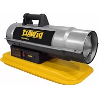
DXH50K - Heating DEWALT - Free user manual and instructions
Find the device manual for free DXH50K DEWALT in PDF.


| Product type | Kerosene forced air heater |
| Brand | DeWALT |
| Model | DXH50K |
| Heating power | 14.7 kW (50,000 BTU/h) |
| Compatible fuel | Kerosene No. 1-K (also No. 2-K, diesel No. 1/2, fuel oil No. 1/2, JP8, Jet A) |
| Fuel consumption | 1.4 L/h |
| Power supply | 115 V, 60 Hz, 3.5 A |
| Minimum operating voltage | 110 V |
| Ignition | Continuous direct spark (13 kV, 10 mA) |
| Fuel tank capacity | 15.1 L (4 gal) |
| Maximum output temperature | 787 °C (1,450 °F) |
| Pump pressure | 24 kPa (3.5 psig) |
| Certification | uCSA_C |
| Electrical protection | 10 A in-line fuse |
| Usage type | Outdoor or well-ventilated indoor (0.19 m² opening at floor and ceiling) |
| Main functions | Direct heating, forced air |
| Safety | Heat limiter, CdS cell, safety switch, automatic shutoff |
| Maintenance | Cleaning air and fuel filters, draining tank, replacing nozzle |
| Spare parts | Available from DeWALT (filters, nozzle, CdS cell, etc.) |
| Warranty | 1 year limited |
Frequently Asked Questions - DXH50K DEWALT
User questions about DXH50K DEWALT
0 question about this device. Answer the ones you know or ask your own.
Ask a new question about this device
Download the instructions for your Heating in PDF format for free! Find your manual DXH50K - DEWALT and take your electronic device back in hand. On this page are published all the documents necessary for the use of your device. DXH50K by DEWALT.
USER MANUAL DXH50K DEWALT
If you have questions or comments, contact us.
Kerosene Forced-Air Heater DXH50K, DXH75KT, DXH135KT, DXH185KT
Kérosène air forcé Chauffage DXH50K, DXH75KT, DXH135KT, DXH185KT
El queroseno calentador de aire forzado DXH50K, DXH75KT, DXH135KT, DXH185KT
40799
WARNING: READ INSTRUCTIONS
CAREFULLY: Read and follow all instructions. Place instructions in a safe place for future reference. Do not allow anyone who has not read these instructions to assemble, adjust or operate the heater.
⚠AVERTISSEMENT: VEUILLEZ LIRE ATTENTIVEMENT
Definitions: Safety Guidelines
The definitions below describe the level of severity for each signal word. Please read the manual and pay attention to these symbols.
▲DANGER: Indicates an imminently hazardous situation which, if not avoided, will result in death or serious injury.
▲WARNING: Indicates a potentially hazardous situation which, if not avoided, could result in death or serious injury.
CAUTION: Indicates a potentially hazardous situation which, if not avoided, may result in minor or moderate injury.
▲NOTICE: Indicates a practice not related to personal injury which, if not avoided, may result in property damage.
WARNING: DO NOT OPERATE THIS HEATER UNTIL YOU READ AND UNDERSTAND THIS INSTRUCTION MANUAL FOR SAFETY, OPERATION, AND MAINTENANCE INSTRUCTIONS.
▲ WARNING:
Failure to comply with the precautions and instructions provided with this heater, can result in death, serious bodily injury and property loss or damage from hazards of fire, explosion, burn, asphyxiation, carbon monoxide poisoning, and/or electrical shock.
Only persons who can understand and follow the instructions should use or service this heater.
If you need assistance or heater information such as an instructions manual, labels, etc. Contact the manufacturer. Save these instructions for future reference.
ADANGER: CARBON MONOXIDE CAN KILL YOU
This heater produces carbon monoxide. Do not use in occupied spaces. Ventilate building, room or other enclosed spaces where heater has been used before entering. Never use in a vehicle, camper or tent.
▲WARNING: Not for home or recreational vehicle use. Do not use to cook or warm food.
▲WARNING: Fire, burn, inhalation, and explosion hazard. Keep solid combustibles, such as building materials, paper or cardboard, a safe distance away from the heater as recommended by the instructions. Never use the heater in spaces which do or may contain volatile or airborne combustibles, or products such as gasoline, solvents, paint thinner, dust particles or unknown chemicals.
WARNING: RISK OF FIRE OR EXPLOSION
- Do not use gasoline, naphtha or volatile fuels.
- Stop heater and allow to cool before adding fuels.
• Always fill outdoors away from open flame. - Do not use external fuel source.
- Do not operate heater where flammable liquids or vapors may be present.
- Do not start heater when chamber is hot.
- Do not start heater when excess fuel has accumulated in the chamber.
WARNING:
Combustion by products produced when using this product contains carbon monoxide, a chemical known to the State of California to cause cancer and birth defects (or other reproductive harm). This product contains chemicals known to the State of California to cause cancer and birth defects or other reproductive harm.
WARNING: RISK OF ELECTRICAL SHOCK
- Plug power cord into a properly grounded 3-wire receptacle. - Do not operate in wet or damp conditions.
WARNING: For Models DXH50K & DXH75K
Not suitable for use on wood floors or other combustible materials. When used the heater should rest on a suitable insulating material at least 1 inch thick and extending 3 feet or more beyond the heater in all directions.
WARNING: Fuels used in liquefied propane gas appliances, and the products of combustion of such fuel, can expose you to chemicals including benzene, which is known to the State of California to cause cancer and cause birth defects or other reproductive harm. For more information visit www.P65Warnings.ca.gov.
▲WARNING: This product can expose you to chemicals including lead and lead compounds, which are known to the State of California to cause cancer and birth defects or other reproductive harm. Wash your hands after handling this product. For more information visit www.P65Warnings.ca.gov.
- Do not store or use gasoline or other flammable vapors and liquids in the vicinity of this or any other appliance. WHAT TO DO IF YOU SMELL GAS?
- Open windows.
• DO NOT try to light any appliance.
• DO NOT operate any electrical switches. - DO NOT use any telephone in building. Immediately call the local gas supplier from an outside telephone. Follow the gas supplier's instructions.
- DO NOT touch any electrical switch; do not use any phone in your building.
- If you cannot reach your gas supplier, call the Fire Department.
CONTENTS
WARNINGS....2-3
HEATER SPECIFICATIONS....3
OPERATING PRECAUTIONS....4
SAFETY PRECAUTIONS 4
OPERATING INSTRUCTIONS....4-5
MAINTENANCE, STORAGE AND SERVICE 5-7
WIRING DIAGRAM 7
TROUBLE SHOOTING 8
PARTS LISTS/EXPLODED VIEWS 9-11
WARRANTY 12
INSTRUCTIONS FOR ORDERING PARTS 12
Specifications
CAUTION: CSA certified for use with only No. 1-K kerosene fuel. Factory Tested: No.2-K kerosene, No.1 or No.2 Diesel, No.1 or No.2 fuel oil or JP8 Jet A fuel
| Model | DXH50K DXH75KT DXH135KT | DXH185KT | ||
| Burn Rate: | 50,000 Btu/hr (14.7 kW) | 75,000 Btu/hr (22 kW) | 135,000 Btu/hr (39.5 kW) | 185,000 Btu/hr (54.2 kW) |
| Fuel Rate: | 0.37 gal/hr (1.4 L/hr) | 0.55 gal/hr (2.1 L/hr) | 1.0 gal/hr (3.8 L/hr) | 1.37 gal/hr (5.2 L/hr) |
| Electrical Input: | 115V, 60Hz, 3.5A | 115V, 60Hz, 4A | 115V, 60Hz, 5.5A | 115V, 60Hz, 5.5A |
| Line Protection: | 10 Amps | 10 Amps | 20 Amps | 20 Amps |
| Min. Operating voltage: | 110 V | 110 V | 110 V | 110 V |
| Pressure Setting: | 3.5 psig (24 kPa) | 4.2 psig (29 kPa) | 6.8 psig (47 kPa) | 7.2 psig (49.7 kPa) |
| Max. Outlet Temperature: | 1450°F (787°C) | 1450°F (787°C) | 1450°F (787°C) | 1450°F (787°C) |
| Fuel Tank Capacity: | 4 gallons (15.1 L) | 6 gallons (22.7 L) | 8.45 gallons (32 L) | 13.5 gallons (51 L) |
| Ignition: | Direct Spark, Continuous | Direct Spark, Continuous | Direct Spark, Continuous | Direct Spark, Continuous |
| Spark Generator: | Igniter, 13kV, 10mA | Igniter, 13kV, 10mA | Igniter, 13kV, 10mA | Igniter, 13kV, 10mA |
| Primary Safety Control: | Solid State Control | Solid State Control | Solid State Control | Solid State Control |
| Certification: | _UCSA_C | _UCSA_C | _UCSA_C | _UCSA_C |
Operating Precautions
WARNING
This is a kerosene, direct-fired, forced air heater. It's intended use is primarily temporary heating of buildings under construction, alteration or repair.
Direct-Fired means that all of the combustion products enter the heated space. Even though this heater operates very close to 100 percent combustion efficiency, it still produces small amounts of carbon monoxide. Carbon monoxide (called CO) is toxic. CO can build up in a heated space and failure to provide adequate ventilation could result in death. Thesymptomsofinadequate ventilation are:
- headache
- dizziness
- burning eyes and nose
- nausea
• dry mouth or sore throat
Be sure to follow advice about ventilation in the Safety Precautions section.
Forced Air means that a blower or fan pushes the air through the heater. Proper combustion depends upon this air flow; therefore, the heater must not be revised, modified or operated with parts removed or missing. Likewise, safety systems must not be circumvented or modified in order to operate the heater. When the heater is to be operated in the presence of other people the user is responsible for properly acquainting those present with the safety precautions and instructions, and of the hazards involved.
Safety Precautions
▲WARNING
-
Certified for use with No.1-K kerosene fuel. Factory tested for use with No.2-K kerosene, No.1 or No.2 Diesel, No.1 or No.2 fuel oil or JP8 Jet A fuel and these fuels may be used as well. Never use gasoline, oil drained from crank cases, naphtha, paint thinners, alcohol or any other highly flammable fuels.
Only store kerosene in containers marked Kerosene or Kerosine. -
Check the heater thoroughly for damage. DO NOT operate a damaged heater.
-
DO NOT modify the heater or operate a heater which has been modified from its original condition.
-
Suitable for outdoor use. For either outdoor or indoor use where adequate
ventilation is provided. Never use in areas normally for habitation. Not for use where exposed to weather.
- Use in well ventilated areas, provide at least 2 sq. ft. (0.19 sq. m.) of opening near the floor and 2 sq. ft. (0.19 sq. m.) near the ceiling directly to outdoors. Increase air openings as marked for each additional heater.
- Always keep combustibles, like paper and wood at least 8 ft. (2.4 m) from the heater outlet and 3 ft. (1.0 m) from the top, sides and inlet. Locate 10 ft. (3.0 m) from canvas or plastic coverings and secure them to prevent flapping movement.
-
Caution: Due to the high surface and exhaust temperatures, adults and children must observe clearances to avoid burns or clothing ignition. Do Not Touch. Keep children, clothing, and combustible away.
-
Install the heater such that it is not directly exposed to water spray, rain and/or water.
-
Never use in occupied spaces and/or where children may be present.
-
Operate only on a stable, level surface. (DXH50K & DXH75K—See wood floor warning).
-
Do not use with duct work. Do not restrict inlet or exit.
-
Use only with electrical power specified. The electrical connection and grounding must comply with National Electrical Code – ANSI/NFPA 70 (USA) and CSA C22.1 Canadian Electrical Code, Part 1 (Canada).
-
Use only a properly grounded 3-prong receptacle or extension cord.
-
Do not move, handle, or service while hot or while in operation.
-
Use only in accordance with local, state (provincial) or national requirements, ordinances and codes.
Operating Instructions
UNPACKING
▲CAUTION: Heavy unit, do not attempt to lift without assistance.
- Remove heater from carton.
- Remove all protective material which may have been applied to the heater for shipment.
- Check the heater for possible shipping damage. If any damage is found immediately contact the manufacturer at 855-805-5745.
ASSEMBLY (For 135,000 and 185,000 BTU/hr models only, see figure 1, page 9.)
Wheels and handles are found in the shipping carton along with mounting hardware. The wheels, axle and mounting hardware are in a package. Tools required are a 5/16" nut driver, 3/8" open or adjustable wrench and standard pliers.
- Assemble the wheels onto the wheel support as shown.
- Install one of the cotter pins into the hole on one end of axle.
- Slide the large washer, then wheel onto the axle next to the cotter pin.
- Slide the spacer onto the axle next to the wheel.
- Slide the partially assembled axle through the wheel support frame.
- Slide the spacer onto the axle next to the wheel support.
- Slide the wheel then large washer onto the axle and hold in place with the remaining cotter pin.
- Install the caps over the larger washers to finish the wheel assembly.
- Slide leg support into place.
- Slide upper handle into place.
- Attach drape guard with included screws. (Canadian requirement).
PREPARING FOR OPERATION
- Check the heater for possible shipping damage. If any is found, immediately contact the manufacturer at 855-805-5745.
- Follow all WARNINGS and Precautions found in this manual.
- Fill the fuel tank with clean kerosene. In extremely cold weather, condensation may develop in the tank and it is recommended that a tablespoon of de-icer be added for each gallon (4 liters) of fuel in the tank. When filling the heater, use at least 2 gallons (8 liters) of fuel. Be sure heater is level and do not overfill. Use a funnel or can with a long fill spout.
IMPORTANT: Before filling fuel tank the first time or after extended
storage periods, drain the fuel tank of any moisture or condensation.
- Locate heater at a safe distance from combustible materials. Models DXH50K & DXH75K are not suitable for use on wood floors or other combustible materials. When used, the heater should rest on suitable insulating material at least 1 inch thick and extending 3 ft. or more beyond the heater in all directions.
HEATER START UP
- Turn thermostat to lowest setting, make sure "ON/OFF" switch is "OFF" position. Plug the heater into a grounded 115V, 60 Hz, 1 ∅ outlet. Turn thermostat to highest setting. Start heater by pushing toggle switch to "I" position (light signifies switch is in "I" position). Adjust thermostat to desired setting. Heater will cycle on/off as heat is required.
EXTENSION CORD REQUIREMENTS: Up to 100' (30.5m) use 16 awg. conductor. 101' - 200' (30.5 - 61.0m) use 14 awg. conductor.
- In cold weather (below 10^ F), starting may be improved by holding a finger over the vent hole of the pump adjustment screw cap until the heater starts.
- This unit is equipped with an interrupt circuit. The reset is integrated into the "I/O" switch. If the unit does not start, toggle the switch to "O", wait 5 min. and toggle the switch to "I".
HEATER SHUT DOWN
Push "ON/OFF" switch to "OFF" position. For extended shutdown, unplug heater from power source.
RESTART AFTER SAFETY SHUTDOWN
Toggle switch to "OFF" position, wait 5 minutes. Restart.
Maintenance and Storage
▲WARNING: To prevent personal injury, unplug the heater from the wall outlet before maintenance.
For maximum efficiency and trouble-free service, make the following periodic maintenance, cleaning and inspections.
Due to varying fuel viscosities and normal component wear the pump pressure on this heater may need to be adjusted. The heater should only be operated at the manufacturer's recommended burner setting.
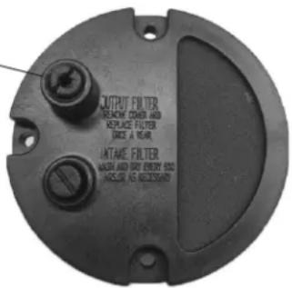
Pressure Adjustment Screw (located at the rear of the heater)
text_image
OUTPUT FILTER WARNING COVER AND REPLACE FILTER ORDER A YEAR. INTAKE FILTER WASH AND RAY ENERGY 500 INCREASE AS NECESSARYADJUSTMENT PROCEDURE:
- Fill fuel tank.
- Start heater.
- Locate the fuel pressure. The pressure adjustment screw is located at the rear of the heater, in the air filter housing cover (slotted adjustment screw).
- The plug directly under the adjustment screw can be used to install a pressure gauge. It is not a second adjust screw.
- Using a flat bladed screw driver, turn the pump pressure adjustment screw clockwise to increase pump pressure and/or counter-clockwise to decrease pump pressure. Base pump pressures can be found in the specifications chart on page 3 of the "Operating Instructions and Owners' Manual".
- For best results, the nose con in the combustion chamber should be cherry red with no dark spots and the flame should not extend beyond the nose cone.
IMPROPER PRESSURE ADJUSTMENT
Problem: Heater does not have a strong consistent flame.
Heater smokes and spits raw fuel.
Nose cone does not get cherry red.
Adjustment: Pump pressure is too low.
Turn adjustment screw clockwise to increase pump pressure.
Problem: Flame extends beyond the end of the heater.
Adjustment: Pump pressure is too high.
Turn adjustment screw counter clockwise to decrease pump pressure.
Daily Maintenance Schedule
- GENERAL. Make general visual inspection of heater for loose or damaged parts. Check nuts and bolts to insure against looseness caused by vibration or rough handling. Damaged parts should be repaired or replaced before using heater again. Check heater operation to be sure it is operating normally (See "Servicing" section for description of normal operation).
- FILTERS. Dirty air or fuel filters will cause an imbalance in the air-fuel mixture. The best indication that this condition exists is an increase in odors or difficulty getting your heater to ignite. This heater should never be operated without the filters in place. If required, clean filters as described under "500 Hours" and "Annual Schedules".
500 Hour Maintenance Schedule
- AIR INTAKE FILTER. Remove and wash the filter element with a mild detergent, dry thoroughly and replace. Do not oil the filter element. If your heater is used where there is considerable dust or dirt, clean as often as necessary (approximately every 50 hrs.).
- REMOVE DUST. Clean heater twice a season (more often under dusty conditions). Remove accumulated dust from the transformer, burner, motor and fan blades with compressed air. Wipe area clean with a clean dry cloth. Inspect area to insure all foreign materials are removed, especially around the burner and combustion area. Safety glasses should be worn when using compressed air.
- CAD CELL. Clean the glass portion of the cad cell with a soft dry cloth.
- NOZZLE. Accumulation of dirt from fuel and carbon from the compressor vanes will eventually fill up the passages in the nozzle, resulting in reduction of fuel and air flow. Pressure will gradually increase giving improper fuel-air mixture and excess odor and smoke. If this occurs, replace the fuel nozzle.
- FUEL TANK. Clean twice a season (during frequently used periods, clean twice a month). Drain and flush the fuel tank with clean fuel oil. Make sure to dispose of waste fuel properly.
Annual Maintenance Schedule
- AIR OUTPUT FILTER. Remove the air output filter and tap the contaminated side gently on a solid object to remove contaminates. Compressed air or liquids should not be used to clean this filter. Reinstall cleaned filter in filter body in the same position as it was when removed. If the filter appears extremely dirty, replace it with a new filter of the same type. When replacing the filter cover, be sure the gasket is firmly in place and the screws in the filter cover are tight to prevent air leaks.
- FUEL FILTER. Remove the fuel filter from fuel line and direct compressed air through the filter in the opposite direction of fuel flow. Safety glasses should be worn when using compressed air.
- AIR AND FUEL LINES. If the air or fuel lines are removed during cleaning, be sure all connections are tight before operating unit.
STORAGE
Store the heater in a dry location free from fumes or dust.
At the end of each heating season, clean the heater as described in the MAINTENANCE section. Drain and flush the fuel tank with clean fuel. The manufacturer recommends completely filling the tank with fuel for extended storage to minimize condensation inside the tank.
SERVICING
WARNING
A hazardous condition may result if a heater is used that has been modified or is not functioning properly.
When the heater is working normally:
* The flame is contained within the heater.
* The flame is essentially yellow.
* There is no strong disagreeable odor, eye burning or other physical discomfort.
* There is no smoke or soot internal or external to the heater.
* There are no unplanned or unexplained shut downs of the heater.
Immediately shut down and do not use a heater that is not working normally. Do not attempt to re-start and use the heater until it has been serviced by qualified service personnel.
Wiring Diagram
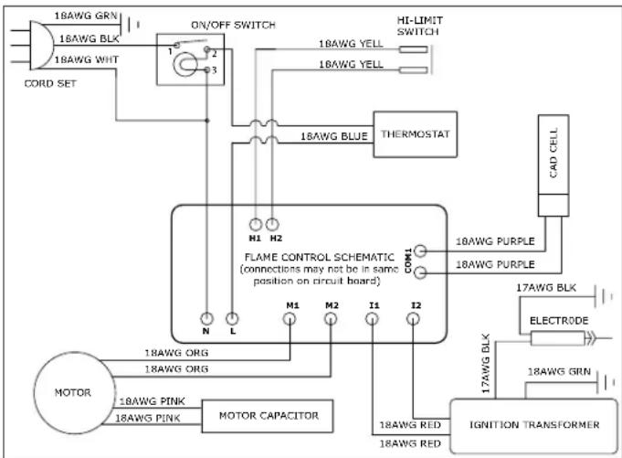
flowchart
graph TD
    A["18AWG GRN"] --> B["ON/OFF SWITCH"]
    C["16AWG BLX"] --> B
    D["18AWG WHT"] --> B
    B --> E["18AWG YELL"]
    B --> F["18AWG YELL"]
    G["CORD SET"] --> B
    H["HI-LIMIT SWITCH"] --> I["18AWG BLUE"]
    I --> J["THERMOSTAT"]
    K["MOTOR"] --> L["18AWG PINK"]
    L --> M["MOTOR CAPACITOR"]
    N["18AWG ORG"] --> O["FLAME CONTROL SCHEMAIC (connections may not be in same position on circuit board)"]
    P["18AWG PINK"] --> O
    Q["18AWG RED"] --> R["IGNITION TRANSFORMER"]
    S["17AWG BLK"] --> T["ELECTRODE"]
    U["18AWG GRN"] --> V["17AWG BLK"]
    W["N"] --> X["L"]
    Y["M1"] --> Z["M2"]
    AA["I1"] --> AB["I2"]
    AC["10AWG PURPLE"] --> AD["COM1"]
    AE["18AWG PURPLE"] --> AD
    AF["CAD CELL"] --> AG["17AWG BLK"]
⚠️ CAUTION: The parts lists and wiring diagram show the heater as it was constructed. Do not use a heater which is different from that shown. Heater performance is effected by air pressure setting. If there is any uncertainty about the air pressure setting, have it checked.
A heater which is not working right must be repaired, but only by a trained, experienced service person.
Diagnostic Safety Shutdown and Trouble Shooting
See the following troubleshooting guide for unit status and corrective action if necessary.
| SYMPTOM TROUBLE SHOOTING | |
| High limit switch Open Circuit | 1) Make sure heater is cooled off, toggle switch to "OFF" position, wait 5 minutes and retry. |
| Sparks, calling for flame, but 1) Check wiring to motor (per wiring schematic in manual).no or slow motor operation 2) Make sure that the pressure gauge plug is in place and not damaged.3) Adjust pressure for proper heater operation per manual.4) With heater disconnected from AC source, rotate fan clockwise to verify motor is free.5) Remove air filter housing from motor and inspect the pump rotor for damage. If damaged, replace rotor assembly.6) If wiring is correct, pump rotor is okay, and motor is not rotating freely, replace motor or power-pack assembly.7) If problem persists, replace oil flame control assembly.8) Check for spark arcing from the electrode assembly, to the combustion cylinder.9) Check the cad cell for continuity. | |
| No Spark2) Check wiring to igniter (per wiring schematic in manual).3) Check gap between electrode probes (2.3 - 3 mm).4) Still no spark, replace igniter assembly.5) Replace oil flame control assembly. | 1) Check length and gauge of extension cord for proper amp. draw. (Check requirements on page 5.) |
| Abnormal Motor Operation -Motor overheats or Stops 2) With heater disconnected from AC source, rotate fan clockwise to verify motor is free.3) Remove air filter housing from motor and inspect the pump rotor for damage. If damaged, replace rotor assembly.4) If wiring is correct, pump rotor is okay, and motor is not rotating freely, replace motor or power-pack assembly.5) Replace oil flame control assembly. | 1) Motor speed too low (Motor should operate at 3450rpm, except 50K at 1550rpm) - Replace motor. |
| Unable to Detect Flame 1) Check wiring to cad cell (per wiring schematic in manual).2) Clean cad cell photo cell.a) Slide cad cell out of cad cell holder.b) Push the photo cell out of the black rubber cad cell housing by pushing on the 2 purple wires.c) Clean the photo cell with a soft cloth and rubbing alcohol.d) Pull the photo cell back into the cad cell housing and reinstall into holder.e) Test heater.3) If the heater still does not operate, replace cad cell.4) Replace oil flame control assembly. | |
| Flame Control Failure2) Replace oil flame control assembly. | 1) Check wiring in heater (per wiring schematic in manual). |
Handle & Wheel Assembly Parts List
Handle and wheel assembly for
DXH135K and DXH185K only.
| PARTS LIST - Handle & Wheel Ass'y | ||
| Ref. Item # Item # Description | ||
| DXH135K | DXH185K | |
| 1 27102 27114 Upper Handle w/Spring Clips | ||
| 2 27103 27103 Lower Handle, Right | ||
| * 27103 27103 Lower Handle, Left | ||
| 3 27103 27103 Leg Support, Right | ||
| * 27103 27103 Leg Support, Left | ||
| 4 27115 27126 Support Leg | ||
| 5 26976 22113 Front Leg | ||
| 6 22168 22184 Axle | ||
| 7 40981 40981 Wheel Assembly | ||
| 8 28749 28749 Large Retainer Washer | ||
| 9 28750 28750 Cotter Pin | ||
| 10 28751 28751 Hub Cap | ||
| 11 21897 21897 Wheel Spacer | ||
| 12** 21906 21907 Drape Guard | ||
| * 28787 28787 Hardware Kit | ||
| DXH50K | DXH75K | |
| 12** 21905 21905 Drape Guard | ||
| * Not Shown | ||
| ** Required in Canada | ||

text_image
Figure 1.text_image
Exploded view diagram of a refrigerator with numbered parts for identificationDXH50K, DXH75KT, DXH135KT, DXH185KT
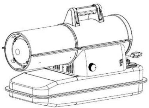
natural_image
Line drawing of a portable air purifier device with cylindrical housing and base tray (no text or symbols)Warning:
Use only manufacturer's replacement parts. Use of any other parts could cause injury or death. Replacement parts are only available direct from the factory and must be installed by a qualified service agency.
PARTS ORDERING INFORMATION:
PURCHASING: Accessories may be purchased at any DeWALT ^® local dealer or direct from the factory
FOR INFORMATION REGARDING SERVICE:
Please call Toll-Free 855-805-5745
www.DEWALT.com
Our office hours are 8:00 AM – 5:00 PM, EST, Monday through Friday.
Please include the model number, date of purchase, and description of problem in all communication.
LIMITED WARRANTY:
DeWALT ^® warrants its heaters and accessories to be free from defects in material and workmanship for a period of 1 year from date of purchase. DeWALT ^® will repair or replace this product free of charge if it has been proven to be defective within the 1-year period, and is returned at customer expense with proof of purchase to DeWALT ^® within the warranty period.
DeWALT®, GUARANTEED TOUGH® and the yellow and black color scheme are trademarks of the DeWALT Industrial Tool Co., used under license. ©2020 DeWALT. EGI/Enerco Group Inc. Under license from DeWALT Industrial Tool Co

UL-733, CSA B140.8, CSA B140.9.3
NE JAMAIS LAISSER LE CHAUFFAGE SANS SURVEILLANCE PENDANT LE BRÛLAGE!
If you have questions or comments, contact us.
Kerosene Forced-Air Heater DXH50K, DXH75KT, DXH135KT, DXH185KT
Kérosène air forcé Chauffage DXH50K, DXH75KT, DXH135KT, DXH185KT
El queroseno calentador de aire forzado DXH50K, DXH75KT, DXH135KT, DXH185KT
40799
WARNING: READ INSTRUCTIONS
CAREFULLY: Read and follow all instructions. Place instructions in a safe place for future reference. Do not allow anyone who has not read these instructions to assemble, adjust or operate the heater.
⚠️ AVERTISSEMENT: VEUILLEZ LIRE ATTENTIVEMENT
SPÉCIFICATIONS DE LA FOURNAISE....3
PRÉCAUTIONS LIÉES AU FONCTIONNEMENT ....4
PRÉCAUTIONS DE SÉCURITÉ....4
CONSIGNES D'UTILISATION 4-5
ENTRETIEN, RANGEMENT ET SERVICE 5-7
SCHÉMA DU CÂBLAGE....7
GUIDE DE DÉPANNAGE 8
LISTES DES PIÈCES/VUES ÉCLATÉES....9-11
GARANTIE 12
DIRECTIVES POUR COMMANDER DES PIÈCES....12
Spécifications
ARRÊT DE LA FOURNAISE
Handle and wheel assembly for
DXH135K and DXH185K only.
text_image
Figure 1.NE JAMAIS LAISSER LE CHAUFFAGE SANS SURVEILLANCE PENDANT LE BRÛLAGE!
Liste des pièces
text_image
Exploded view diagram of a refrigerator with numbered parts for identificationNE JAMAIS LAISSER LE CHAUFFAGE SANS SURVEILLANCE PENDANT LE BRÛLAGE!
DEWALT®
MANUEL D'INSTRUCTIONS
natural_image
Technical line drawing of a portable air purifier device (no text or symbols)AVERTISSEMENT :
UL-733, CSA B140.8, CSA B140.9.3
If you have questions or comments, contact us.
Kerosene Forced-Air Heater DXH50K, DXH75KT, DXH135KT, DXH185KT
Kérosène air forcé Chauffage DXH50K, DXH75KT, DXH135KT, DXH185KT
El queroseno calentador de aire forzado DXH50K, DXH75KT, DXH135KT, DXH185KT
40799
WARNING: READ INSTRUCTIONS
CAREFULLY: Read and follow all
instructions. Place instructions in a safe place for future reference. Do not allow anyone who has not read these instructions to assemble, adjust or operate the heater.
⚠ AVERTISSEMENT: VEUILLEZ LIRE ATTENTIVEMENT
text_image
Exploded view diagram of a refrigerator with numbered parts for identificationnatural_image
Technical line drawing of a portable air purifier device (no text or symbols)Advertencia:
UL-733, CSA B140.8, CSA B140.9.3