
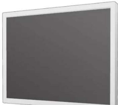
MultiSync 90GX² Pro - Monitor NEC - Free user manual and instructions
Find the device manual for free MultiSync 90GX² Pro NEC in PDF.
| Product Type | Color LCD Monitor |
| Brand | NEC |
| Model | MultiSync 90GX² Pro |
| Screen Diagonal | 19 inches |
| Native Resolution | 1280 x 1024 |
| Weight (max.) | 4.8 kg |
| Power Supply | 220-240 V AC, 50/60 Hz |
| Power Consumption | ENERGY STAR compliant |
| Connectivity | Analog video input (mini D-SUB 15-pin), digital video input (DVI-D), USB port |
| Main Functions | Tilt/swivel, auto adjustment, OSM, DV mode (movie, game, photo), color control (6 presets including sRGB and NATIVE) |
| OSM Settings | Brightness, contrast, image position, sharpness, language (8 languages), OSM lock, timer |
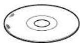
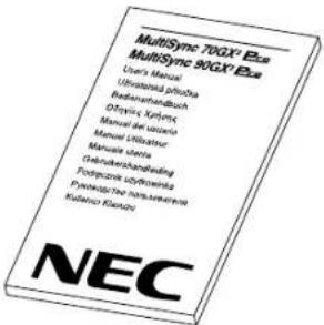
| Supplied Accessories | Power cord, analog video cable, DVI video cable, USB cable, cable cover, CD-ROM (PDF manual) |
| Screen Cleaning | Soft, dry cloth; do not use abrasive or solvent-based products |
| Housing Cleaning | Soft, slightly damp cloth with mild detergent |
| Safety | Do not open the housing; risk of electric shock; disconnect before cleaning; use only with an approved mounting arm |
| Certifications | ENERGY STAR, CE, ISO 13406-2 |
| Maintenance and Repairability | No user-serviceable parts; contact qualified technician |
| Warranty | Standard manufacturer's warranty (not specified) |
Frequently Asked Questions - MultiSync 90GX² Pro NEC
User questions about MultiSync 90GX² Pro NEC
0 question about this device. Answer the ones you know or ask your own.
Ask a new question about this device
Download the instructions for your Monitor in PDF format for free! Find your manual MultiSync 90GX² Pro - NEC and take your electronic device back in hand. On this page are published all the documents necessary for the use of your device. MultiSync 90GX² Pro by NEC.
USER MANUAL MultiSync 90GX² Pro NEC
MultiSync 70GX ^2 Pro MultiSync 90GX ^2 Pro
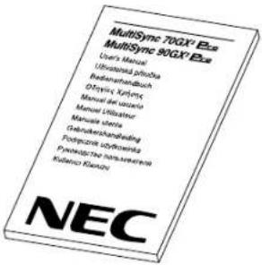
User's Manual
Canadian Department of Communications Compliance Statement
DOC: This Class B digital apparatus meets all requirements of the Canadian Interference-Causing Equipment Regulations.
C-UL: Bears the C-UL Mark and is in compliance with Canadian Safety Regulations according to CAN/CSA C22.2 No. 60950-1.
FCC Information
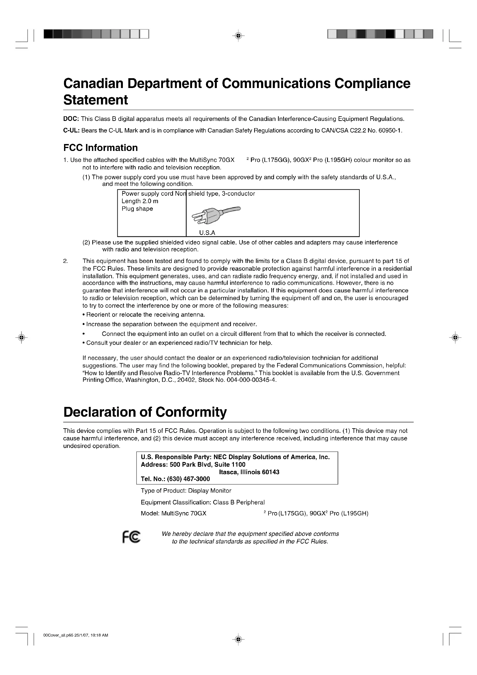
- Use the attached specified cables with the MultiSync 70GX ^2 Pro (L175GG), 90GX ^2 Pro (L195GH) colour monitor so as not to interfere with radio and television reception.
(1) The power supply cord you use must have been approved by and comply with the safety standards of U.S.A., and meet the following condition.
Power supply cord Nor Length 2.0 m Plug shape
shield type, 3-conductor
U.S.A
(2) Please use the supplied shielded video signal cable. Use of other cables and adapters may cause interference with radio and television reception.
-
This equipment has been tested and found to comply with the limits for a Class B digital device, pursuant to part 15 of the FCC Rules. These limits are designed to provide reasonable protection against harmful interference in a residential installation. This equipment generates, uses, and can radiate radio frequency energy, and, if not installed and used in accordance with the instructions, may cause harmful interference to radio communications. However, there is no guarantee that interference will not occur in a particular installation. If this equipment does cause harmful interference to radio or television reception, which can be determined by turning the equipment off and on, the user is encouraged to try to correct the interference by one or more of the following measures:
-
Reorient or relocate the receiving antenna.
- Increase the separation between the equipment and receiver.
- Connect the equipment into an outlet on a circuit different from that to which the receiver is connected.
- Consult your dealer or an experienced radio/TV technician for help.
If necessary, the user should contact the dealer or an experienced radio/television technician for additional suggestions. The user may find the following booklet, prepared by the Federal Communications Commission, helpful: "How to Identify and Resolve Radio-TV Interference Problems." This booklet is available from the U.S. Government Printing Office, Washington, D.C., 20402, Stock No. 004-000-00345-4.
Declaration of Conformity
This device complies with Part 15 of FCC Rules. Operation is subject to the following two conditions. (1) This device may not cause harmful interference, and (2) this device must accept any interference received, including interference that may cause undesired operation.
U.S. Responsible Party: NEC Display Solutions of America, Inc.
Address: 500 Park Blvd, Suite 1100
Itasca, Illinois 60143
Tel. No.: (630) 467-3000
Type of Product: Display Monitor
Equipment Classification: Class B Peripheral
Model: MultiSync 70GX
^2 Pro (L175GG), 90GX ^2 Pro (L195GH)

We hereby declare that the equipment specified above conforms to the technical standards as specified in the FCC Rules.
TCODevelopment

Congratulations!
The display you have just purchased carries the TCO'03 Displays label. This means that your display is designed, manufactured and tested according to some of the strictest quality and environmental requirements in the world. This makes for a high performance product, designed with the user in focus that also minimizes the impact on our natural environment.
Some of the features of the TCO'03 Display requirements:
Ergonomics
- Good visual ergonomics and image quality in order to improve the working environment for the user and to reduce sight and strain problems. Important parameters are luminance, contrast, resolution, reflectance, colour rendition and image stability.
Energy
- Energy-saving mode after a certain time – beneficial both for the user and the environment
- Electrical safety
Emissions
- Electromagnetic fields
- Noise emissions
Ecology
- The product must be prepared for recycling and the manufacturer must have a certified environmental management system such as EMAS or ISO 14 001.
- Restrictions on: - chlorinated and brominated flame retardants and polymers - heavy metals such as cadmium, mercury and lead.
The requirements included in this label have been developed by TCO Development in co-operation with scientists, experts, users as well as manufacturers all over the world. Since the end of the 1980s TCO has been involved in influencing the development of IT equipment in a more user-friendly direction. Our labelling system started with displays in 1992 and is now requested by users and IT-manufacturers all over the world.
For more information, please visit
www.tcodevelopment.com
Manufacturer's Recycling and Energy Information
NEC DISPLAY SOLUTIONS is strongly committed to environmental protection and sees recycling as one of the company's top priorities in trying to minimize the burden placed on the environment. We are engaged in developing environmentally-friendly products, and always strive to help define and comply with the latest independent standards from agencies such as ISO (International Organisation for Standardization) and TCO (Swedish Trades Union).
Disposing of your old NEC product
The aim of recycling is to gain an environmental benefit by means of re-use, upgrading, reconditioning or reclamation of material. Dedicated recycling sites ensure that environmentally harmful components are properly handled and securely disposed. To ensure the best recycling of our products, NEC DISPLAY SOLUTIONS offers a variety of recycling procedures and gives advice on how to handle the product in an environmentally sensitive way, once it has reached the end of its life.
All required information concerning the disposal of the product and country-specific information on recycling facilities can be found on our following websites:
http://www.nec-display-solutions.com/greencompany/ (in Europe),
http://www.nec-display.com (in Japan) or
http://www.necdisplay.com (in USA).
Energy Saving
This monitor features an advanced energy saving capability. When a VESA Display Power Management Signalling (DPMS) Standard signal is sent to the monitor, the Energy Saving mode is activated. The monitor enters a single Energy Saving mode.
70GX² Pro
| Mode Power consumption LED colour | ||
| Normal Operation Approx. 47W Blue | ||
| Energy Saving Mode Less than 2W Amber | ||
| Off Mode Less than 1W Unlit | ||
90GX² Pro
| Mode Power consumption LED colour | ||
| Normal Operation Approx. 52W Blue | ||
| Energy Saving Mode Less than 2W Amber | ||
| Off Mode Less than 1W Unlit | ||
WEEE Mark (European Directive 2002/96/EC)
Within the European Union
EU-wide legislation, as implemented in each Member State, requires that waste electrical and electronic products carrying the mark (left) must be disposed of separately from normal household waste. This includes monitors and electrical accessories, such as signal cables or power cords. When you need to dispose of your NEC display products, please follow the guidance of your local authority, or ask the shop where you purchased the product, or if applicable, follow any agreements made between yourself and NEC.
The mark on electrical and electronic products only applies to the current European Union Member States.
Outside the European Union
If you wish to dispose of used electrical and electronic products outside the European Union, please contact your local authority so as to comply with the correct disposal method.
Chinese RoHS-information relevant for Chinese market
Warning, Caution ...... English-1
Declaration ...... English-1
Contents ...... English-2
Quick Start ...... English-3
Controls ...... English-7
Recommended use ...... English-9
TO PREVENT FIRE OR SHOCK HAZARDS, DO NOT EXPOSE THIS UNIT TO RAIN OR MOISTURE. ALSO, DO NOT USE THIS UNIT'S POLARIZED PLUG WITH AN EXTENSION CORD RECEPTACLE OR OTHER OUTLETS UNLESS THE PRONGS CAN BE FULLY INSERTED.
REFRAIN FROM OPENING THE CABINET AS THERE ARE HIGH VOLTAGE COMPONENTS INSIDE. REFER SERVICING TO QUALIFIED SERVICE PERSONNEL.

CAUTION:
CAUTION

TO REDUCE THE RISK OF ELECTRIC SHOCK, MAKE SURE POWER CORD IS UNPLUGGED FROM WALL SOCKET. TO FULLY DISENGAGE THE POWER TO THE UNIT, PLEASE DISCONNECT THE POWER CORD FROM THE AC OUTLET.DO NOT REMOVE COVER (OR BACK). NO USER SERVICEABLE PARTS INSIDE. REFER SERVICING TO QUALIFIED SERVICE PERSONNEL.

This symbol warns user that uninsulated voltage within the unit may have sufficient magnitude to cause electric shock. Therefore, it is dangerous to make any kind of contact with any part inside this unit.

This symbol alerts the user that important literature concerning the operation and maintenance of this unit has been included. Therefore, it should be read carefully in order to avoid any problems.
Caution:
When operating the MultiSync 70GX ^2 Pro, 90GX ^2 Pro with a 220-240V AC power source in Europe, use the power cord provided with the monitor.
In the UK, a BS approved power cord with a moulded plug has a Black (five Amps) fuse installed for use with this equipment. If a power cord is not supplied with this equipment please contact your supplier.
When operating the MultiSync 70GX ^2 Pro, 90GX ^2 Pro with a 220-240V AC power source in Australia, use the power cord provided with the monitor. If a power cord is not supplied with this equipment please contact your supplier.
For all other cases, use a power cord that matches the AC voltage of the power outlet and has been approved by and complies with the safety standard of your particular country.
Declaration
Declaration of the Manufacturer
We hereby certify that the colour monitor MultiSync 70GX ^2 Pro (L175GG), 90GX ^2 Pro (L195GH) are in compliance with
Council Directive 73/23/EEC: -EN 60950-1
Council Directive 89/336/EEC:
- EN 55022
- EN 61000-3-2
- EN 61000-3-3
- EN 55024
and marked with

NEC Display Solutions, Ltd.
4-13-23, Shibaura,
Minato-Ku
Tokyo 108-0023, Japan

ISO 13406-2

Windows is a registered trademark of Microsoft Corporation. NEC is a registered trademark of NEC Corporation. ENERGY STAR is a U.S. registered trademark.
OmniColor is a registered trademark of NEC Display Solutions Europe GmbH in the countries of EU and Switzerland.
ErgoDesign is a registered trademark of NEC Display Solutions, Ltd. in Austria, Benelux, Denmark, France, Germany, Italy, Norway, Spain, Sweden, U.K.
NaViSet is a trademark of NEC Display Solutions Europe GmbH in the countries of EU and Switzerland.
MultiSync is a registered trademark of NEC Display Solutions, Ltd. in the countries of U.K., Italy, Austria, Netherlands, Switzerland, Sweden, Spain, Denmark, Germany, Norway and Finland.
All other brands and product names are trademarks or registered trademarks of their respective owners.
As an ENERGY STAR® Partner, NEC Display Solutions of America, Inc. has determined that this product meets the ENERGY STAR guidelines for energy efficiency. The ENERGY STAR emblem does not represent EPA endorsement of any product or service.
Contents
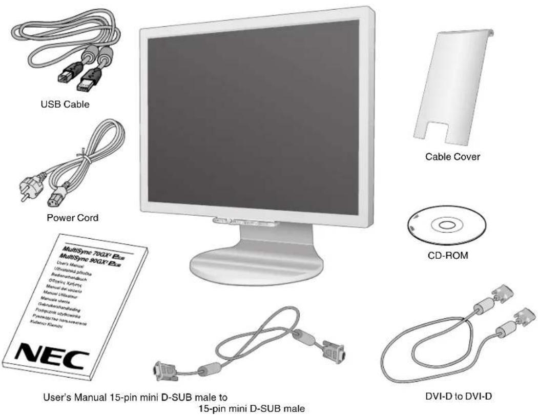
Your new NEC MultiSync LCD monitor box* should contain the following:
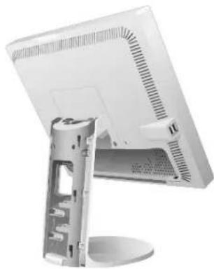
- MultiSync 70GX ^2 Pro, 90GX ^2 Pro monitor with tilt/swivel adjust stand
- Power Cord
• V ideo Signal Cable (15-pin mini D-SUB male to 15-pin mini D-SUB male)
• V ideo Signal Cable (DVI-D to DVI-D) - USB Cable
- User's Manual
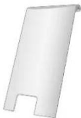
- Cable Cover
- CD ROM (includes complete User's Manual in PDF format). Tosee the User's Manual, Acrobat Reader 4.0 must be installed on your PC.
* Remember to save your original box and packing material to transport or ship the monitor.
Quick Start
Toattach the MultiSync LCD monitor to your system, follow these instructions:
- Turn off the power to your computer.
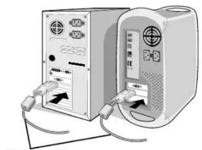
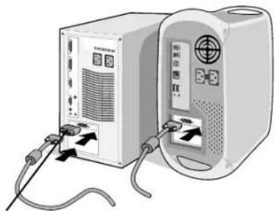
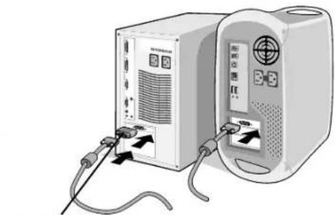
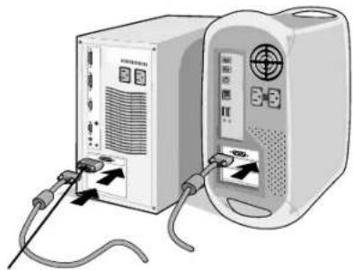
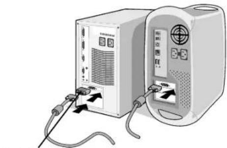
- For the PC or MAC with DVI digital output: Connect the DVI signal cable to the connector of the display card in your system (Figure A.1). Tighten all screws.
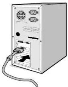
For the PC with Analog output: Connect the 15-pin mini D-SUB signal cable to the connector of the display card in your system (Figure A.2). Tighten all screws.
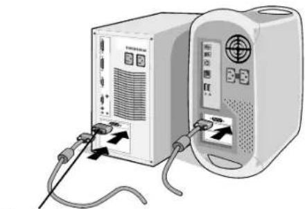
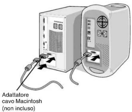
For the MAC: Connect the Macintosh cable adapter to the computer, then attach the 15-pin mini D-SUB signal cable to the Macintosh cable adapter (Figure B.1). Tighten all screws.
natural_image
Illustration of two computer units connected by cables, one with ports labeled 'V', showing internal wiring (no text or symbols present)DVI signal cable
Figure A.1 Figure B.1
natural_image
Front view of a computer tower with attached cable and drive port (no visible text or labels)Figure A.2
natural_image
Illustration of two connected devices with cables and ports, no visible text or symbolsMacintosh Cable Adapter (not included)
NOTE: Some Macintosh systems do not require a Macintosh cable adapter.
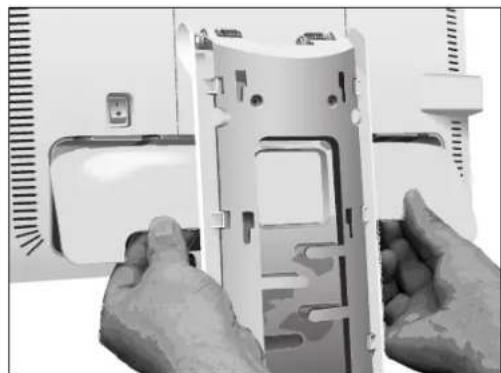
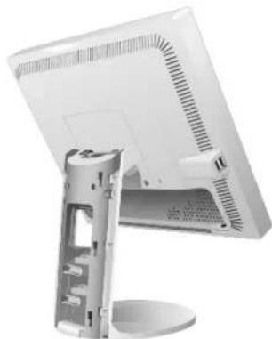
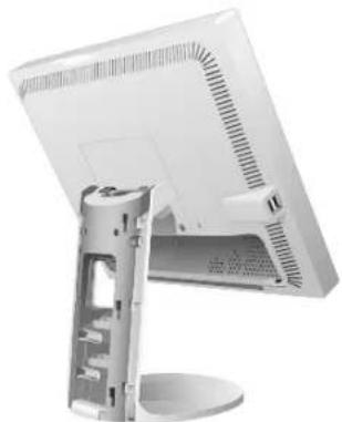
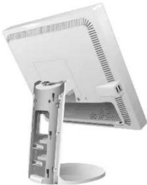
- Remove the connector cover (Figure C.1).
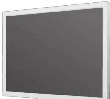
- Place hands on each side of the monitor to tilt the LCD panel 30 degrees angles (Figure C.2).
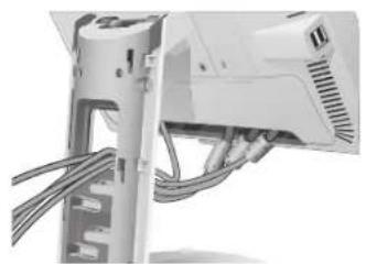
- Connect all cables to the appropriate connectors through the square hole in the stand (Figure C.3).
natural_image
Close-up of hands installing or adjusting a white plastic panel with visible internal components (no text or symbols)Figure C.1 Figure C.2
natural_image
Exterior view of a modern computer monitor with a side panel showing the front panel and screen (no visible text or symbols)
natural_image
Close-up of a computer monitor with cable and ventilation slots (no visible text or symbols)Figure C.3
English-3
- Place the connector cover onto the back cabinet (Figure C.4).
- Place all cables into the hooks (Figure C.5).
- Place hands on each side if the monitor to tilt the LCD panel back 5° (Figure C.6).
natural_image
Close-up of a white electronic device with cables and connectors (no visible text or symbols)
natural_image
Close-up of a mechanical or electrical component with wires and mounting base (no visible text or symbols)Figure C.4 Figure C.5
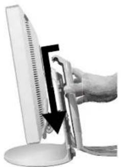
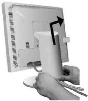
- Place the cable cover onto the stand (Figure C.6). To remove the cable cover, push the notch at the bottom of the cover up (towards the top of the monitor) in order to unhook the cover from the stand (Figure C.7).
natural_image
Hand inserting a black-and-white cable into a computer monitor (no text or symbols visible)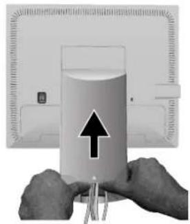
natural_image
Close-up of hands holding a glass with liquid and an upward arrow, no visible text or symbolsFigure C.6 Figure C.7
- Connect the power cord to the power outlet (Figure D.1).
NOTE: Please refer to Caution section of this manual for proper selection of AC power cord.
11. The vacation switch on the back side of the monitor must be turned on (Figure D.1). Turn on the monitor with the front power button and the computer.
NOTE: The vacation switch is a true on/off switch. If this switch is on the OFF position, the monitor cannot be turned on using the front button. DO NOT switch on/off repeatedly.
12. No-Touch Auto Adjust automatically adjusts the monitor to optimal settings upon initial setup for most timings. For further adjustments, use the following OSM controls:
• Auto Adjust Contrast (Analog input only)
• Auto Adjust (Analog input only)
Refer to the Controls section of this User's Manual for a full description of these OSM controls.
NOTE: If you have any problems, please refer to the Troubleshooting section of this User's Manual.
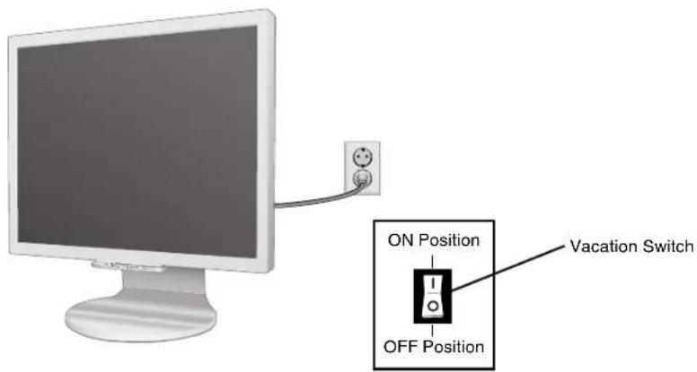
Figure D.1
English-4
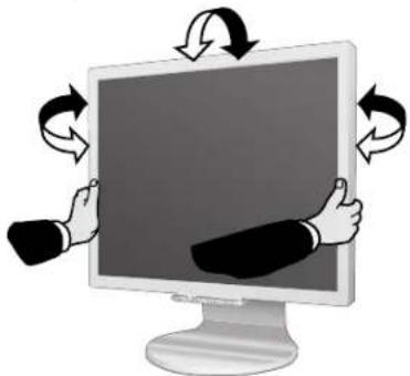
Tilt and Swivel
Grasp both sides of the monitor screen with your hands and adjust the tilt and swivel as desired (Figure TS.1).
NOTE: Handle with care when tilting and swivelling the monitor screen.
natural_image
Illustration of hands interacting with a computer monitor displaying a blank screen, surrounded by curved arrows indicating rotation or refresh (no text or symbols present)Figure TS.1
Remove Monitor Stand for Mounting
To prepare the monitor for alternate mounting purposes:
- Place hands on each side of the monitor to tilt the LCD panel 5 degrees angles. Remove the cable cover (Figure M.1). Remove the connector cover (Figure M.2).
- Disconnect all cables.
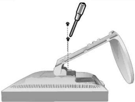
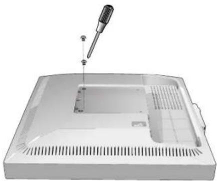
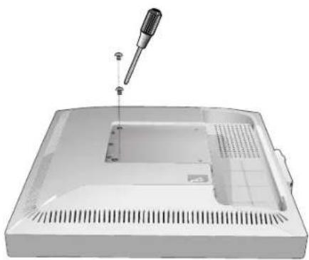
- Place monitor face down on a non-abrasive surface (Figure M.3).
- Remove the 2 screws connecting the stand to the monitor (Figure M.3).
natural_image
Close-up of hands using a computer monitor to press or attach cable, with an arrow indicating the cable's direction (no text or symbols visible)Figure M.1

natural_image
Close-up of hands assembling a cylindrical electronic component with internal circuitry (no visible text or symbols)Figure M.2
natural_image
Illustration of a mechanical device with a screwdriver inserted, showing a lever mechanism (no text or symbols)Figure M.3
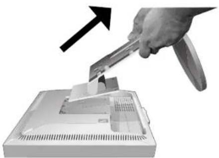
- Lift up the stand to unlatch the upper hooks and remove the stand (Figure M.4).
- Remove the 2 screws on the top of the monitor (Figure M.5). The monitor is now ready for mounting in an alternate manner.
- Connect the cables and place the connector cover on the back of the monitor.
- Reverse this process to re-attach stand.
NOTE: Use only VESA-compatible alternative mounting method. Handle with care when removing stand.
natural_image
Hand using a power tool to cut or remove a device from an open computer case (no text or symbols visible)
natural_image
3D rendering of a mechanical device with a screwdriver inserted into a housing (no text or symbols visible)Figure M.4 Figure M.5
Flexible Arm Installation
This LCD monitor is designed for use with a flexible arm. To mount the monitor to a flexible arm:
- Follow the instructions on how Remove Monitor Stand for Mounting to remove the stand.
- Use the 4 screws to attach the arm to the monitor (Figure F.1).
NOTE: The LCD monitor should only be used with an approved arm (e.g. GS mark). To meet the safety requirements, the monitor must be mounted to an arm, which guarantees the necessary stability under consideration of the weight of the monitor.
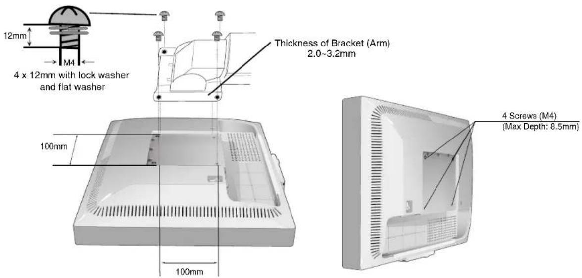
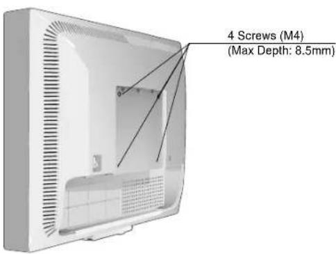
Weight of LCD assembly: 70GX ^2 Pro - 4.0kg (MAX) 90GX ^2 Pro - 4.8kg (MAX)
Figure F.1
Controls
OSM (On-Screen Manager) control buttons on the front of the monitor function as follows:
To access OSM menu, press any of the control buttons (MENU/EXIT, Left, Right, Down, Up).
To change signal input, press the SELECT button.
Tochange DV MODE, press the RESET/DV MODE button.
NOTE: OSM must be closed in order to change signal input.

Button
Menu
MENU/EXIT
Open OSM main menu.
Exits the OSM controls.
Exits to the OSM main menu.
4-Direction-Key
Up

RightLeft
Down
Left/Right
Moves the highlighted area left/right to select control menus.
Moves the bar left/right to increase or decrease the adjustment.
Direct adjust of brightness if HOT KEY is set to ON.
Enters the OSM menu if HOT KEY is set to OFF.
Down/Up
Moves the highlighted area down/up to select one of the controls.
Direct adjust of contrast if HOT KEY is set to ON.
Enters the OSM menu if HOT KEY is set to OFF.
SELECT
Active Auto Adjust function. Enter the OSM sub menu.
RESET/DV MODE Resets the highlighted control menu to the factory setting. Switches the DV Mode.
NOTE: When RESET is pressed in the main and sub-menu, a warning window will appear allowing you to cancel the RESET function by pressing the MENU/EXIT button.

Brightness/Contrast Controls
BRIGHTNESS
Adjusts the overall image and background screen brightness.
CONTRAST
Adjusts the image brightness in relation to the background.
DV MODE
Dynamic Visual Mode allows you to select setting for Movie, Photo and etc.
AUTO CONTRAST (Analog input only)
Adjusts the image displayed to optimal settings.

Auto Adjust (Analog input only)
Automatically adjusts the Image Position, H. Size and Fine settings.

Image Controls (Analog input only)
LEFT / RIGHT
Controls Horizontal Image Position within the display area of the LCD.
DOWN / UP
Controls Vertical Image Position within the display area of the LCD.
H.SIZE
Adjusts the horizontal size by increasing or decreasing this setting.
FINE
Improves focus, clarity and image stability by increasing or decreasing this setting.

Colour Control System
Colour Control System: Six colour presets select the desired colour setting (sRGB and NATIVE colour presets are standard and cannot be changed).
R,G,B: Increases or decreases Red, Green or Blue colour depending upon which is selected. The change in colour will appear on screen and the direction (increase or decrease) will be shown by the bars.
NATIVE: Original colour presented by the LCD panel that is unadjustable.
sRGB: sRGB mode dramatically improves the colour fidelity in the desktop environment by a single standard RGB colour space. With this colour supported environment, the operator could easily and confidently communicate colour without further colour management overhead in the most common situations.
NOTE: When MOVIE, GAMING, or PHOTO is selected as the DV MODE, NATIVE is selected automatically as the six colour preset and cannot be changed.

Tools
OFF TIMER: Monitor will automatically power-down when the end user has selected a predetermined amount of time.
LED BRIGHTNESS: You can adjust the Blue LED brightness.
HOT KEY: You can adjust the brightness and contrast directly. When this function is set to ON, you can adjust the brightness with left or right control and contrast with up or down control while the OSM menu is off.
DDC/CI: This function allows the DDC/CI function ON or OFF (90GX² Pro only).
FACTORY PRESET: Selecting Factory Preset allows you to reset all OSM control settings back to the factory settings. The RESET button will need to be held down for several seconds to take effect. Individual settings can be reset by highlighting the control to be reset and pressing the RESET button.

Menu Tools
LANGUAGE: OSM control menus are available in eight languages.
OSM LEFT/RIGHT: You can choose where you would like the OSM control image to appear horizontally on your screen.
OSM DOWN/UP: You can choose where you would like the OSM control image to appear vertically on your screen.
OSM Turn Off: The OSM control menu will stay on as long as it is in use. In the OSM Turn Off submenu, you can select how long the monitor waits after the last touch of a button to shut off the OSM control menu.
OSM Lock Out: This control completely locks out access to all OSM control functions without Brightness and Contrast. When attempting to activate OSM controls while in the Lock Out mode, a screen will appear indicating the OSM controls are locked out. To activate the OSM Lock Out function, press SELECT, then right control button and hold down simultaneously. To deactivate the OSM Lock Out, press SELECT, then left control button and hold down simultaneously while in the OSM menu.
RESOLUTION NOTIFIER: This optimal resolution is 1280 x 1024. If ON is selected, a message will appear on the screen after 30 seconds, notifying you that the resolution is not at 1280 x 1024.

Information
The Information menu indicates the current input, display resolution, horizontal and vertical frequency, and polarity settings of the monitor. The model and serial numbers of your monitor are also indicated.
OSM Warning
OSM Warning menus disappear with Exit button.
NO SIGNAL: This function gives a warning when there is no Horizontal or Vertical Sync. After power is turned on or when there is a change of input signal, the No Signal window will appear.
RESOLUTION NOTIFIER: This function gives a warning of use with optimized resolution. After power is turned on or when there is a change of input signal or the video signal doesn't have proper resolution, the Resolution Notifier window will open. This function can be disabled in the Menu Tools.
OUT OF RANGE: When input signal is non-supported timing or the video signal doesn't have proper timing, the Out of Range menu will appear.
Recommended use
Safety Precautions and Maintenance

FOR OPTIMUM PERFORMANCE, PLEASE NOTE THE FOLLOWING WHEN SETTING UP AND USING THE MULTISYNC LCD COLOUR MONITOR:

- DO NOT OPEN THE MONITOR. There are no user serviceable parts inside and opening or removing covers may expose you to dangerous shock hazards or other risks. Refer all servicing to qualified service personnel.
- Do not spill any liquids into the cabinet or use your monitor near water.
- Do not insert objects of any kind into the cabinet slots, as they may touch dangerous voltage points, which can be harmful or fatal or may cause electric shock, fire or equipment failure.
- Do not place any heavy objects on the power cord. Damage to the cord may cause shock or fire.
- Do not place this product on a sloping or unstable cart, stand or table, as the monitor may fall, causing serious damage to the monitor.
- Do not place any objects onto the monitor and do not use the monitor outdoors.
- The inside of the fluorescent tube located within the LCD monitor contains mercury. Please follow the bylaws or rules of your municipality to dispose of the tube properly.
- Do not bend power cord.
- Do not use monitor in high temperatured, humid, dusty, or oily areas.
- Do not cover vent on monitor.
Immediately unplug your monitor from the wall outlet and refer servicing to qualified service personnel under the following conditions:
- When the power supply cord or plug is damaged.
- If liquid has been spilled, or objects have fallen into the monitor.
- If the monitor has been exposed to rain or water.
- If the monitor has been dropped or the cabinet damaged.
- If the monitor does not operate normally by following operating instructions.
- If glass is broken, handle with care.
- If monitor or glass is broken, do not come in contact with the liquid crystal and handle with care.

CAUTION
- Allow adequate ventilation around the monitor so that heat can properly dissipate. Do not block ventilated openings or place the monitor near a radiator or other heat sources. Do not put anything on top of monitor.
- The power cable connector is the primary means of detaching the system from the power supply. The monitor should be installed close to a power outlet which is easily accessible.
- Handle with care when transporting. Save packaging for transporting.
- Image Persistence: Please be aware that LCD Technology may experience a phenomenon known as Image Persistence. Image Persistence occurs when a residual or "ghost" image of a previous image remains visible on the screen. Unlike CRT monitors, LCD monitors' image persistence is not permanent, but constant images being displayed for a long period of time should be avoided. To alleviate image persistence, turn off the monitor for as long as the previous image was displayed. For example, if an image was on the monitor for one hour and a residual image remains, the monitor should be turned off for one hour to erase the image.
NOTE: As with all personal display devices, NEC DISPLAY SOLUTIONS recommends displaying moving images and using a moving screen saver at regular intervals whenever the screen is idle or turning off the monitor when not in use.

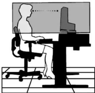
CORRECT PLACEMENT AND ADJUSTMENT OF THE MONITOR CAN REDUCE EYE, SHOULDER AND NECK FATIGUE. CHECK THE FOLLOWING WHEN YOU POSITION THE MONITOR:

- For optimum performance, allow 20 minutes for warm-up.
- Adjust the monitor height so that the top of the screen is at or slightly below eye level. Your eyes should look slightly downward when viewing the middle of the screen.
- Position your monitor no closer than 40 cm and no further away than 70 cm from your eyes. The optimal distance is 50 cm.
- Rest your eyes periodically by focusing on an object at least 20 feet away. Blink often.
- Position the monitor at a 90^ angle to windows and other light sources to minimize glare and reflections. Adjust the monitor tilt so that ceiling lights do not reflect on your screen.
- If reflected light makes it hard for you to see your screen, use an anti-glare filter.
- Adjust the monitor's brightness and contrast controls to enhance readability.
- Use a document holder placed close to the screen.
- Position whatever you are looking at most of the time (the screen or reference material) directly in front of you to minimize turning your head while you are typing.
- Avoid displaying fixed patterns on the monitor for long periods of time to avoid image persistence (after-image effects).
- Get regular eye checkups.
natural_image
Silhouette of a person sitting at a desk with a computer, no text or symbols visibleErgonomics
Torealize the maximum ergonomics benefits, we recommend the following:
- Use the preset Size and Position controls with standard signals.
- Use the preset Colour Setting.
- Use non-interlaced signals with a vertical refresh rate between 60-75 Hz.
- Do not use primary colour blue on a dark background, as it is difficult to see and may produce eye fatigue to insufficient contrast.
Cleaning the LCD Panel
Recommended cleaning of the LCD:
- T o remove dust and dirt from the surface of the LCD panel, wipe gently with a soft cloth.
- Do not rub the LCD panel with rough material.
- Do not press on the surface of the LCD panel.
To avoid scratches
- Do not touch LCD panel with hard objects.
- Use only a soft cloth for cleaning the surface of the LCD panel.
To avoid stains
- Clean fingerprints, water drips, chemical spills and etc. from the LCD panel immediately or discoloration and spot will occur.
- If the LCD panel is rubbed with too much force, cracking may occur, which will lead to abnormalities in the display.
To avoid breakage or screen trouble
- Do not push hard on the LCD panel surface.
- Do not set heavy objects on the LCD panel surface.
- Do not leave the LCD panel under constant pressure.
Cleaning the Cabinet
- Unplug the power supply.
- Use a soft cloth.
- Dampen the cloth with a mild detergent mixed with water, wipe the cabinet and dry with a soft cloth.
NOTE: Many plastics are used on the cabinet surface. DO NOT clean with benzene, alkaline detergent, alcoholic system detergent, glass cleaner, wax, polish cleaner, soap powder or insecticide. Do not touch the cabinet with rubber or vinyl for a prolonged period. These types of fluids and fabrics can cause the paint to deteriorate, crack or peel.

VAROVÁNÍ

CHRAŃTE ZAŘÍZENÍ PŘED DEŠTĚM A VLHKEM. ZABRÁNÍTE TAK NEBEZPEČÍ POŽÁRU NEBO ÚRAZU ELEKTRICKÝM PROUDEM. POLARIZOVANOU ZÁSTRČKU JEDNOTKY NEPOUŽÍVEJTE VE SPOJENÍ SE ZÁSUVKOU PRODLUŽOVACÍ ŠNŮRY NEBO JINÝMI ZÁSUVKAMI, POKUD KOLÍKY NELZE ZCELA ZASUNOUT.
UVNITŘ ZAŘÍZENÍ SE NACHÁZÍ VYSOKONAPĚTOVÉ KOMPONENTY, PROTO SKŘÍŇ NEOTEVÍREJTE. SERVIS SVĚRTE KVALIFIKOVANÉ OSOBĚ.

UPOZORNĚNÍ

UPOZORNĚNÍ: PRO SNÍŽENÍ RIZIKA ÚRAZU ELEKTRICKÝM PROUDEM ZKONTROLUJTE, ZDA JE NAPÁJECÍ ŠŇŮRA ODPOJENA ZE ZÁSUVKY. PRO ÚPLNÉ ODPOJENÍ ZDROJE NAPÁJENÍ OD JEDNOTKY ODPOJTE NAPÁJECÍ ŠŇŮRU Z ELEKTRICKÉ ZÁSUVKY (NEOSTRAŇUJTE KRYT). UVNITŘ SE NENACHÁZEJÍ DÍLY, DO KTERÝCH UŽIVATEL MŮŽE ZASAHOVAT. SERVIS SVĚRTE KVALIFIKOVANÉ OSOBĚ.

NEC Display Solutions, Ltd.
4-13-23, Shibaura,
Minato-Ku
Tokyo 108-0023, Japan

TÜV
Rheinland
Product Safety
ISO 13406-2

natural_image
Coiled network cable with two USB connectors (no text or symbols visible)Kabel USB
natural_image
Front view of a blank computer monitor with a blank screen (no text or symbols visible)
Kryt kabelu

natural_image
Coiled electrical plug and socket (no text or symbols visible)Napájecí šňůra
natural_image
Illustration of a USB cable with two connectors (no text or symbols)
CD-ROM

natural_image
Illustration of a coiled cable or connector with two connectors (no text or symbols)DVI-D do DVI-D
D-SUB-D-SUB
natural_image
Close-up of hands installing or adjusting a white plastic panel with visible internal components (no text or symbols)natural_image
Side view of a white computer monitor with a side-mounted stand and a plastic case (no visible text or symbols)
natural_image
Close-up of a computer monitor with cable and ventilation slots (no visible text or symbols)Obrázek C.3
Česky-3
natural_image
Close-up of a white electronic device with cables and connectors (no visible text or symbols)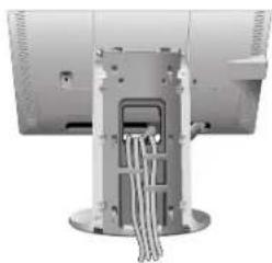
natural_image
Close-up of a mechanical or electrical component with metallic casing and wiring (no visible text or symbols)natural_image
Hand inserting a black arrow into a computer monitor (no text or symbols visible)
natural_image
Close-up of hands holding a glass with a paper airplane icon and an upward arrow, no visible text or symbolsnatural_image
Illustration of hands interacting with a computer monitor displaying a blank screen, surrounded by curved arrows indicating rotation or refresh (no text or symbols present)Obrázek TS.1

natural_image
Close-up of hands using a computer monitor to interact with cables (no visible text or symbols)natural_image
Close-up of hands assembling a cylindrical electronic device with visible internal components (no text or symbols)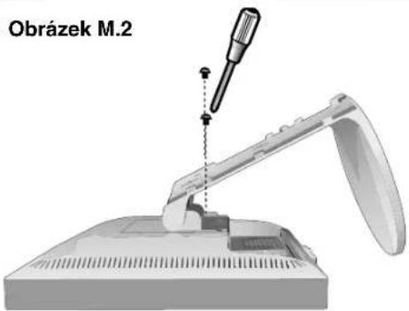
natural_image
Hand using a power tool to cut or remove a device into a plastic tray (no text or symbols visible)natural_image
3D rendering of a mechanical device with a screwdriver inserted into a rectangular housing (no text or symbols visible)natural_image
Silhouette of a person sitting at a desk with a computer, no text or symbols presentErgonomika
NEC Display Solutions, Ltd.
4-13-23, Shibaura,
Minato-Ku
Tokyo 108-0023, Japan

TÜV Rheinland Product Safety
ISO 13406-2

natural_image
Coiled network cable with two USB connectors (no text or symbols visible)USB-Kabel

natural_image
Front view of a flat-screen computer monitor with blank screen (no text or symbols visible)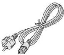
natural_image
Coiled electrical plug and socket (no text or symbols visible)Netzkabel


natural_image
Simple 3D-rendered white rectangular object with a U-shaped cutout at the bottom (no text or symbols)Kabelabdeckung
CD-ROM
natural_image
Illustration of two connected USB connectors with a coiled cable (no text or symbols)natural_image
Simple line drawing of a coiled cable or connector with two connectors (no text or symbols)DVI-D auf DVI-D
natural_image
Close-up of hands installing or adjusting a white plastic panel with visible internal components (no text or symbols)natural_image
Side view of a white computer monitor with a side panel showing internal components (no visible text or symbols)
natural_image
Close-up of a computer monitor with cable and ventilation slots (no visible text or symbols)Abbildung C.3
Deutsch-3
natural_image
Close-up of a white electronic device with cables and connectors (no visible text or symbols)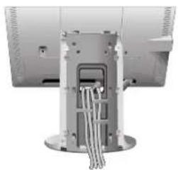
natural_image
Close-up of a mechanical or electrical component with metallic pins and wires (no visible text or symbols)natural_image
Hand inserting a black cable into a computer monitor (no text or symbols visible)
natural_image
Close-up of hands holding a cylindrical object with an upward arrow, next to a device panel (no visible text or symbols)natural_image
Illustration of hands interacting with a computer monitor displaying a blank screen, surrounded by curved arrows indicating rotation or refresh (no text or symbols present)Abbildung TS.1
natural_image
Close-up of hands using a computer monitor to press cable, with an arrow indicating the cable's direction (no text or symbols visible)
natural_image
Close-up of hands installing or adjusting a mechanical component with visible internal structure (no text or symbols)natural_image
Hand using a power tool to cut or remove a device into a flatbed box (no text or symbols visible)natural_image
3D rendering of a mechanical device with a screwdriver inserted into a rectangular housing (no text or symbols visible)natural_image
Silhouette of a person sitting at a desk using a computer, viewed from behind (no text or symbols present)NEC Display Solutions, Ltd.
4-13-23, Shibaura,
Minato-Ku
natural_image
Close-up of hands installing or adjusting a white plastic device casing (no visible text or symbols)Σχήμα Γ.1 Σχήμα Γ.2
natural_image
Computer monitor with front panel and side panel, no visible text or symbols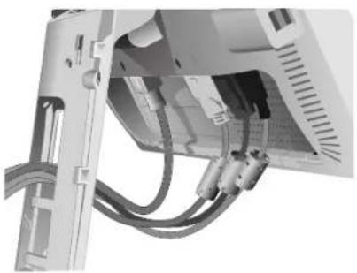
natural_image
Close-up of a computer monitor with cable and ventilation slots (no visible text or symbols)natural_image
Close-up of a mechanical device with cables and a mounted sensor array (no visible text or symbols)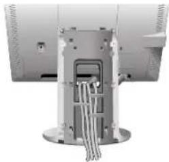
natural_image
Close-up of a mechanical or electrical component with wires inserted, no visible text or symbolsΣχήμα Γ.4 Σχήμα Γ.5
natural_image
Hand inserting a black arrow into a computer monitor (no text or symbols visible)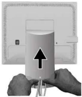
natural_image
Close-up of hands holding a cylindrical object with an arrow pointing upward, next to a device panel (no visible text or symbols)Σχήμα Γ.6 Σχήμα Γ.7
natural_image
Illustration of hands interacting with a computer monitor displaying a blank screen, surrounded by curved arrows indicating rotation or refresh (no text or symbols present)Σχήμα ΤΣ.1
natural_image
Close-up of hands using a computer monitor to interact with cable (no visible text or symbols)Σχήμα Μ.1 Σχήμα Μ.2

natural_image
Close-up of hands assembling a cylindrical electronic component with visible internal structure (no text or symbols)
natural_image
Hand using a power tool to cut or remove a device into a flatboard (no text or symbols visible)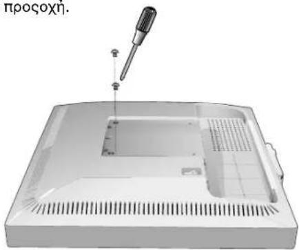
natural_image
3D rendering of a medical device casing with a pipette inserted, showing internal components and a small component (no text or symbols visible)Σχήμα Μ.4 Σχήμα Μ.5
H. SIZE (OPIZONTIO MEΓΕΘΟΣ)
natural_image
Silhouette of a person sitting at a desk using a computer, with no visible text or symbolsΕργονομία
natural_image
Front view of a computer tower with attached cable and ports (no visible text or labels)Figura A.2
natural_image
Illustration of two connected devices with cables and ports, no visible text or symbolsnatural_image
Close-up of hands installing or adjusting a white plastic device casing (no visible text or symbols)Figura C.1 Figura C.2
natural_image
Exterior view of a modern office monitor with a side panel and front panel (no visible text or symbols)
natural_image
Close-up of a computer monitor with cable and ventilation slots (no visible text or symbols)Figura C.3
Español-3
natural_image
Close-up of a white electronic device with cables and connectors (no visible text or symbols)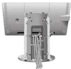
natural_image
Close-up of a mechanical or electrical component with metallic components and wires (no visible text or symbols)Figura C.4 Figura C.5
natural_image
Hand holding a computer monitor with a black scroll, no visible text or symbols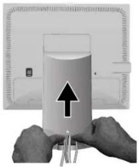
natural_image
Close-up of hands holding a glass with a rising arrow, next to a wall-mounted device (no visible text or symbols)Figura C.6 Figura C.7
natural_image
Illustration of a computer monitor with a cable and a power outlet cable (no text or symbols)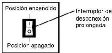
natural_image
Illustration of hands interacting with a computer monitor displaying a blank screen, surrounded by curved arrows indicating rotation or refresh (no text or symbols present)Figura TS.1
natural_image
Close-up of hands using a computer monitor to press cable, with a black arrow indicating the cable's direction (no text or symbols visible)Figura M.1 Figura M.2

natural_image
Close-up of hands installing or adjusting a mechanical component with visible internal structure (no text or symbols)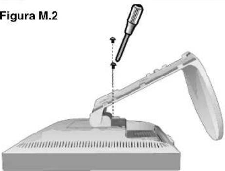
natural_image
3D illustration of a mechanical device with a screwdriver inserted, labeled 'Figura M.2' (no other text or symbols)Figura M.3
Español-5
natural_image
Hand using a power tool to remove or adjust internal components of a device (no text or symbols visible)Figura M.4 Figura M.5
natural_image
3D rendering of a medical or electronic device with a pipette inserted into a rectangular casing (no text or symbols visible)natural_image
Silhouette of a person sitting at a desk with a computer, no text or symbols visibleErgonomía
Figure A.1 Figure B.1

natural_image
Front view of a computer tower with attached cable and drive port (no visible text or labels)Figure A.2

natural_image
Illustration of a computer setup with two connected devices, one showing ports and cables (no text or symbols visible)natural_image
Close-up of hands installing or adjusting a white plastic door panel (no visible text or symbols)Figure C.1 Figure C.2

natural_image
Side view of a computer monitor with a side panel showing internal components (no visible text or symbols)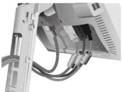
natural_image
Close-up of a computer monitor with visible cables and connectors (no text or symbols)Figure C.3
Français-3
natural_image
Close-up of a white electronic device with cables and connectors (no visible text or symbols)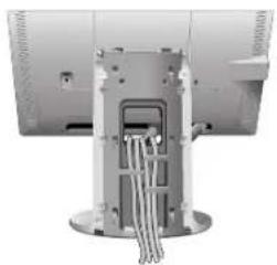
natural_image
Close-up of a mechanical or electrical component with wires and mounting base (no visible text or symbols)Figure C.4 Figure C.5
natural_image
Hand inserting a black-and-white cable into a computer monitor (no text or symbols visible)
natural_image
Close-up of hands holding a glass with a paper and a pencil, showing an upward arrow (no text or symbols visible)Figure C.6 Figure C.7
natural_image
Illustration of hands interacting with a computer monitor displaying a blank screen, surrounded by curved arrows indicating rotation or refresh (no text or symbols present)Figure TS.1
natural_image
Person using a computer monitor to press or attach cable, with a black arrow indicating the cable's direction (no text or symbols visible)Figure M.1 Figure M.2

natural_image
Close-up of hands assembling a cylindrical electronic device with internal components (no visible text or symbols)
natural_image
Diagram of a mechanical device with a screwdriver inserted, labeled Figure M.2 (no text or symbols on the diagram itself)Figure M.3
Français-5
natural_image
Hand using a power tool to cut or remove a device into a plastic housing (no text or symbols visible)
natural_image
3D rendering of a mechanical device with a screwdriver inserted into a rectangular housing (no text or symbols visible)Figure M.4 Figure M.5
Installation du bras flexible
natural_image
Silhouette of a person sitting at a desk with a computer, no text or symbols visibleErgonomie
NEC Display Solutions, Ltd.
4-13-23, Shibaura,
Minato-Ku
natural_image
Front view of a computer tower with attached cable and drive port (no visible text or labels)Figura A.2
natural_image
Close-up of hands installing or adjusting a white plastic device component (no visible text or symbols)Figura C.1 Figura C.2

natural_image
Exterior view of a modern office monitor with front panel and side panel (no visible text or symbols)
natural_image
Close-up of a computer monitor with visible cables and connectors (no text or symbols)Figura C.3
Italiano-3
natural_image
Close-up of a white electronic device with cables and connectors (no visible text or symbols)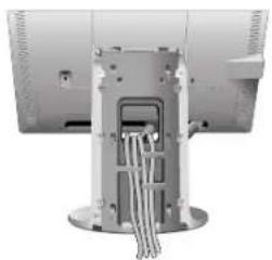
natural_image
Close-up of a mechanical or electrical component with wires inserted into a central housing (no visible text or symbols)Figura C.4 Figura C.5
natural_image
Hand inserting a black rectangular component into a computer monitor (no text or symbols visible)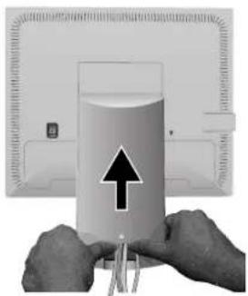
natural_image
Close-up of hands holding a cylindrical object with an upward arrow, next to a computer monitor (no visible text or symbols)Figura C.6 Figura C.7
natural_image
Illustration of hands interacting with a computer monitor displaying a blank screen, surrounded by curved arrows indicating rotation or refresh (no text or symbols present)Figura TS.1
natural_image
Person using a computer monitor to interact with cables (no visible text or symbols)Figura M.1 Figura M.2

natural_image
Close-up of hands assembling a cylindrical electronic device with visible internal components (no text or symbols)
natural_image
Diagram of a robotic arm with a screwdriver inserted, labeled 'Figura M.2' (no other text or symbols)Figura M.3
Italiano-5
natural_image
Hand using a power tool to cut or remove a device into a plastic housing (no text or symbols visible)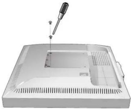
natural_image
3D rendering of a mechanical device with a screwdriver inserted into a rectangular housing (no text or symbols visible)Figura M.4 Figura M.5
natural_image
Silhouette of a person sitting at a desk with a computer, no text or symbols visibleErgonomia
NEC Display Solutions, Ltd.
4-13-23, Shibaura,
Minato-Ku
Tokyo 108-0023, Japan

natural_image
Close-up of hands installing or adjusting a white plastic door panel (no visible text or symbols)natural_image
Front view of a white computer monitor with ventilation grilles and a side-mounted stand (no visible text or symbols)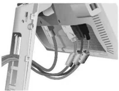
natural_image
Close-up of a computer monitor with cable and ventilation slots (no visible text or symbols)natural_image
Close-up of a white electronic device with cables and connectors (no visible text or symbols)
natural_image
Close-up of a mechanical or electrical component with metallic pins and wires (no visible text or symbols)natural_image
Hand inserting a black-and-white icon into a computer monitor (no text or symbols visible)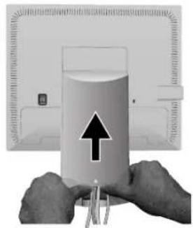
natural_image
Close-up of hands holding a cylindrical object with an upward arrow, next to a device panel (no visible text or symbols)natural_image
Illustration of hands interacting with a computer monitor displaying a blank screen, surrounded by curved arrows indicating rotation or refresh (no text or symbols present)Illustratie TS.1
natural_image
Person using a computer monitor to interact with cables (no visible text or symbols)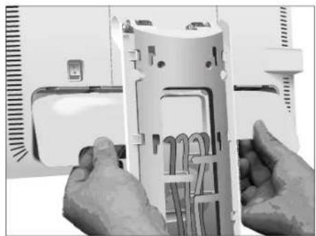
natural_image
Close-up of hands assembling a cylindrical electronic device with internal components (no visible text or symbols)natural_image
Illustration of a mechanical device with a tool inserted, showing a base and handle (no text or symbols)Illustratie M.3
Nederlands-5
natural_image
Hand using a power tool to cut or remove a device from a computer case (no text or symbols visible)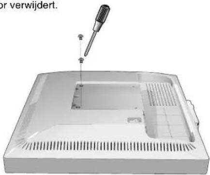
natural_image
3D rendering of a device casing with a screwdriver inserted, showing internal components and ventilation slots (no text or symbols)Brightness/Contrast Controls (Helderheid/contrast)
BRIGHTNESS (Helderheid)
natural_image
Silhouette of a person sitting at a desk using a computer, no text or symbols visibleErgonomie
NEC Display Solutions, Ltd.
4-13-23, Shibaura,
Minato-Ku
Tokyo 108-0023, Japonia

ISO 13406-2

natural_image
Two electronic devices connected by cables, one with ports labeled 'V', showing internal wiring (no readable text or symbols)natural_image
Front view of a computer tower with attached cable and ports (no visible text or labels)Rysunek A.2
natural_image
Illustration of two connected devices with cables and connectors, no visible text or symbolsnatural_image
Close-up of hands installing or adjusting a white plastic door panel (no visible text or symbols)natural_image
Exterior view of a computer monitor with visible ventilation grille and side panel (no text or symbols)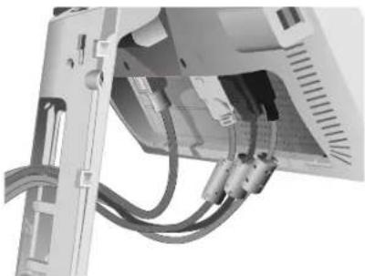
natural_image
Close-up of a computer monitor with visible cables and ports (no text or symbols)Rysunek C.3
Polski-4
natural_image
Close-up of a mounted electronic device with cables and connectors (no visible text or symbols)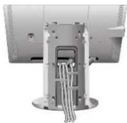
natural_image
Close-up of a mechanical or electronic component with metallic parts and wires, no visible text or symbolsnatural_image
Hand inserting a black-and-white icon into a computer monitor (no text or symbols visible)
natural_image
Close-up of hands holding a small object with an upward arrow, next to a computer monitor (no visible text or symbols)natural_image
Illustration of a computer monitor with hands giving thumbs-up gestures, surrounded by curved arrows indicating rotation (no text or symbols)Rysunek TS.1
natural_image
Close-up of hands using a computer monitor to press or attach cable, with a black arrow indicating the cable's direction (no text or symbols visible)
natural_image
Close-up of hands assembling a mechanical component with visible internal structure (no text or symbols)DOWN/UP (POZYCJA PIONOWA)
natural_image
Silhouette of a person sitting at a desk with a computer, no text or symbols presentErgonomia
natural_image
Two horizontal grayscale color swatches with a central crosshair and alignment lines (no text or symbols)
natural_image
Two isolated geometric symbols: a crosshair and a square with crosshairs, both on a plain background (no text or labels)Polski-12

ПРЕДУПРЕЖДЕНИЕ

NEC Display Solutions, Ltd.
4-13-23, Shibaura,
Minato-Ku
Tokyo 108-0023, Japan

BZ 02

ISO 13406-2

natural_image
Coiled network cable with two USB connectors (no text or symbols visible)Кабель USB
natural_image
Front view of a flat-screen computer monitor with blank screen (no text or symbols visible)
natural_image
Coiled electrical plug and socket (no text or symbols visible)Кабель питания
natural_image
Simple 3D-rendered white rectangular object with a U-shaped cutout at the bottom (no text or symbols)Крышка кабеля

CD ROM

natural_image
Illustration of two connected USB connectors with a coiled cable (no text or symbols)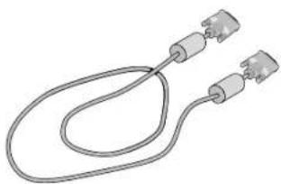
natural_image
Pure electrical circuit lines without any symbolsDVI-D κ DVI-D
natural_image
Illustration of two connected computer units with cables and connectors (no text or symbols visible)natural_image
Front view of a computer tower drive with cable and ports (no visible text or labels)Рисунок А.2
natural_image
Illustration of a computer setup with two connected devices, one front-mounted and one back-mounted, showing ports and cables (no text or symbols visible)natural_image
Close-up of hands installing or adjusting a white plastic panel with visible internal components (no text or symbols)natural_image
Computer monitor with front panel and side panel, showing blank screen and rear panel (no text or symbols visible)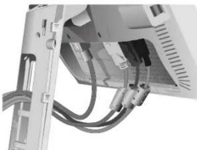
natural_image
Close-up of a computer monitor with visible cables and connectors (no text or symbols)natural_image
Close-up of a white electronic device with cables and connectors (no visible text or symbols)
natural_image
Close-up of a mechanical or electrical component with metallic pins and wires (no visible text or symbols)Рисунок С.4 Рисунок С.5
natural_image
Hand inserting a black-and-white icon into a computer monitor (no text or symbols visible)
natural_image
Close-up of hands holding a cylindrical object with an upward arrow, next to a device panel (no visible text or symbols)natural_image
Illustration of hands interacting with a computer monitor, showing curved arrows indicating rotation or refresh (no text or symbols present)Рисунок TS.1
natural_image
Close-up of hands using a computer monitor to press cable, with an arrow indicating the cable's direction (no text or symbols visible)
natural_image
Close-up of hands assembling a cylindrical electronic device with internal components (no visible text or symbols)natural_image
Hand using a power tool to cut or remove a device from a plastic tray (no text or symbols visible)natural_image
3D rendering of a mechanical device with a screwdriver inserted into a housing (no text or symbols visible)natural_image
Silhouette of a person sitting at a desk with a computer, no text or symbols visibleЭргономика
NEC Display Solutions, Ltd.
4-13-23, Shibaura,
Minato-Ku
Tokyo 108-0023, Japonya

ISO 13406-2

natural_image
Illustration of two connected computer units with cables and connectors (no text or symbols visible)natural_image
Front view of a computer tower with power cord and cable (no visible text or labels)Şekil A.2
natural_image
Illustration of a computer setup with two connected devices and cables (no visible text or symbols)natural_image
Close-up of hands installing or adjusting a 3D-printed plastic component (no visible text or symbols)Şekil C.1 Şekil C.2
natural_image
Computer monitor with rear panel and side-mounted drive mechanism (no visible text or symbols)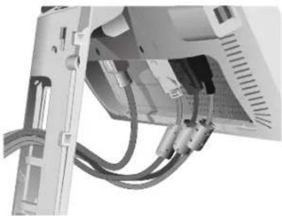
natural_image
Close-up of a computer monitor with visible cables and ports (no text or symbols)Şekil C.3
Türkçe-3
natural_image
Close-up of a white electronic device with cables and connectors (no visible text or symbols)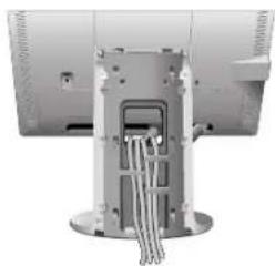
natural_image
Close-up of a mechanical or electronic component with wires inserted, no visible text or symbolsŞekil C.4 Şekil C.5
natural_image
Hand inserting a black-and-white icon into a computer monitor (no text or symbols visible)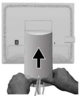
natural_image
Close-up of hands holding a cylindrical object with an upward arrow, next to a device (no visible text or symbols)Şekil C.6 Şekil C.7
natural_image
Illustration of hands interacting with a computer monitor displaying a blank screen, surrounded by curved arrows indicating rotation or refresh (no text or symbols present)Şekil TS.1
natural_image
Close-up of hands using a computer monitor to press cable, with an arrow indicating the cable's direction (no text or symbols visible)Şekil M.1 Şekil M.2

natural_image
Close-up of hands assembling a cylindrical electronic device with internal components (no visible text or symbols)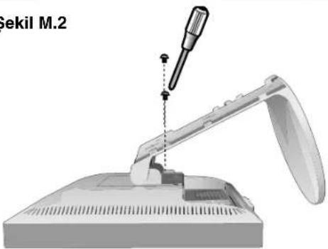
natural_image
Mechanical assembly diagram showing a tool inserted into a device with a spool, labeled 'Sekil M.2' (no other text or symbols)Şekil M.3
Türkçe-5
natural_image
Hand using a power tool to remove or transfer a device into a flatbed box (no text or symbols visible)Şekil M.4 Şekil M.5
natural_image
3D rendering of a mechanical device with a screwdriver inserted into a rectangular housing (no text or symbols visible)natural_image
Silhouette of a person sitting at a desk with a computer, no text or symbols visible
NEC

Printed on recycled paper
Printed in China
Part No. ____


- MultiSync 70GX 2 Pro MultiSync 90GX 2 Pro
- Canadian Department of Communications Compliance Statement
- FCC Information
- Declaration of Conformity
- TCODevelopment
- Congratulations!
- Ergonomics
- Energy
- Emissions
- Ecology
- Manufacturer's Recycling and Energy Information
- Disposing of your old NEC product
- Energy Saving
- WEEE Mark (European Directive 2002/96/EC)
- Within the European Union
- Outside the European Union
- Chinese RoHS-information relevant for Chinese market
- CAUTION
- Caution:
- Declaration
- Declaration of the Manufacturer
- Contents
- Quick Start
- Tilt and Swivel
- Remove Monitor Stand for Mounting
- Flexible Arm Installation
- Controls
- OSM (On-Screen Manager) control buttons on the front of the monitor function as follows:
- Button
- Menu
- MENU/EXIT
- 4-Direction-Key
- Left/Right
- Down/Up
- SELECT
- Brightness/Contrast Controls
- BRIGHTNESS
- CONTRAST
- DV MODE
- AUTO CONTRAST (Analog input only)
- Auto Adjust (Analog input only)
- Image Controls (Analog input only)
- LEFT / RIGHT
- DOWN / UP
- H.SIZE
- FINE
- Colour Control System
- Tools
- Menu Tools
- Information
- OSM Warning
- Recommended use
- Safety Precautions and Maintenance
- CORRECT PLACEMENT AND ADJUSTMENT OF THE MONITOR CAN REDUCE EYE, SHOULDER AND NECK FATIGUE. CHECK THE FOLLOWING WHEN YOU POSITION THE MONITOR:
- Cleaning the LCD Panel
- To avoid scratches
- To avoid stains
- To avoid breakage or screen trouble
- Cleaning the Cabinet
- VAROVÁNÍ
- UPOZORNĚNÍ
- Ergonomika
- SIZE (OPIZONTIO MEΓΕΘΟΣ)
- Εργονομία
- Ergonomía
- Installation du bras flexible
- Ergonomie
- Ergonomia
- Brightness/Contrast Controls (Helderheid/contrast)
- BRIGHTNESS (Helderheid)
- DOWN/UP (POZYCJA PIONOWA)
- ПРЕДУПРЕЖДЕНИЕ
- Эргономика
- NEC
Brand : NEC
Model : MultiSync 90GX² Pro
Category : Monitor