
SCG100 - Swimming Pool GRE - Free user manual and instructions
Find the device manual for free SCG100 GRE in PDF.
| Product Type | Salt electrolysis system for swimming pool |
| Model | SCG100 (MOD.21) |
| Brand | Gre |
| Supply Voltage | 230 V AC, 50/60 Hz |
| Chlorine Production | 17 to 21 g/h |
| Pool capacity (temperate 16-24°C) | 100 m³ |
| Pool capacity (hot +25°C) | 80 m³ |
| Salinity range | 5 to 12 g/l |
| Operating temperature | +15 to 40°C |
| Number of electrodes | 7 |
| Electrode type | Titanium with self-cleaning coating |
| Expected electrode lifespan | 8,000 to 10,000 hours |
| Production levels | 0%, 50%, 75%, 100% |
| Polarity reversal | Programmable 2h/2h or 3h/3h + test mode |
| Minimum flow rate | 3 m³/h |
| Cell material | Transparent methacrylate |
| Pipe connection | PVC glue Ø 63 mm |
| Maximum recommended pressure | 1 kg/cm² |
| Protection rating | IP24 |
| Net weight (including packaging) | 8.5 kg |
| Safety features | Flow/gas detector, high/low salinity alarm |
| External control inputs | 2 inputs for automatic cover and ORP controller |
| Warranty | 2 years (electrodes: 2 years or 3,000 hours) |
Frequently Asked Questions - SCG100 GRE
User questions about SCG100 GRE
0 question about this device. Answer the ones you know or ask your own.
Ask a new question about this device
Download the instructions for your Swimming Pool in PDF format for free! Find your manual SCG100 - GRE and take your electronic device back in hand. On this page are published all the documents necessary for the use of your device. SCG100 by GRE.
USER MANUAL SCG100 GRE
natural_image
Exterior view of a self-mounted device labeled 'Gre' with a black box and a transparent nightlight bulb (no readable text beyond branding)Instruction Manual - Manual de Instrucciones Manuel d'instructions - Bedienungsanleitung Manuale delle instruzioni - Handleiding met instructies Manual de instruções
We reserve to change all of part of the articles or contents of this document, without prior notice.
IMPORTANT: The instruction manual you are holding includes essential information on the safety measures to be implemented for installation and start-up. Therefore, the installer as well as the user must read the instructions before beginning installation and start-up. Keep this manual future reference.

natural_image
Symbol of a trash bin with crossed lines indicating no waste or discharge (no text or labels)Disposal of waste electrical and electronic domestic systems in the Europea Union
All the products marked with this symbol indicate that the product shall not be mixed or disposed with your household waste at their end of use. It is responsibility of the user to eliminate this kind of wastes depositing them in recycling point adapted for the selective disposal of electrical and electronic wastes. The suitable recycling and treatment of these wastes contributes in essential way to the preservation of the Environment and the health of the users. For further information regarding the points of collection of this type of wastes, please contact to the dealer where you acquired the product or to your municipal authority.
a
The instructions given in this manual describe the operation and maintenance of salt electrolysis systems. For optimum performance of the salt electrolysis systems, we recommend you to follow the instructions given below:
1. CHECK THE CONTENTS OF THE PACK:
You should find the following elements inside the box:
- Power supply.
- Electrolysis cell.
• Operation Manual.
2. CARACTERISTICAS GENERALES:
When the salt electrolysis system is installed, a quantity of salt must be dissolved into the swimming pool water. This salty water then passes through the electrolysis cell that is located in the plant room. The salt electrolysis system consists of two elements: an electrolysis cell and a power supply. The electrolysis cell contains a quantity of titanium plates (electrodes) and when a weak electrical current is passed through the plates inside the electrolysis cell, there is chlorine production. Maintaining a level of chlorine in swimming pool water keeps the water sanitised and healthy to swim in. The salt electrolysis system will manufacture chlorine whenever the pool circulation system (pump and filter) is operational.
The power supply is provided with various safety devices, which are activated in case of irregular operation of the system, as well as a microprocessor driven control system. The salt electrolysis systems have an automatic cleaning system that avoids scale formation on the electrodes
3. SAFETY WARNINGS AND RECOMMENDATIONS:
• The equipment should be assembled and handled by truly qualified people.
• Current electrical and accident prevention regulations should be followed.
- Under no circumstances will the manufacturer be held responsible for the assembly, installation or start-up, nor any handling or fitting of components unless they are carried out on its premises.
- The salt electrolysis systems operate at 230VAC, 50/60 Hz. Do not attempt to alter the system to operate at a different voltage.
- Check that all the electrical connectors are well tightened to avoid false contacts and their consequent overheating.
- Before installing or replacing any component, disconnect the equipment from the mains, and use exclusively spare parts supplied by the manufacturer.
- Taking into account the fact that the equipment produces heat, it must be installed in places with sufficient ventilation. Fan openings should be kept free of any element that could obstruct them. The equipment should not be installed near flammable materials.
- The salt electrolysis systems have an IP24 protection degree. They should never be installed in places susceptible to flooding.
POWER SUPPLY:
| DESCRIPTION | MODEL | |
| SCG60 (MOD.12) SCG100 (MOD.21) | ||
| Standard working voltage 230 V AC, 50 Hz./60 Hz. | ||
| Output (dc) 6 A x 2 3.5 A x 6 | ||
| Producción (g/h) 10 - 12 17 - 21 | ||
| Pool volume ( m^3 )Warm: 16 - 24°CHot: +25°C | 6050 | 10080 |
| Flow detection Gas detector | ||
| Salinity /Temperature range 5 ... 12 g./l. / +15 - 40 °C | ||
| Electrodes | SELF-CLEANING coated TitaniumEstimated lifetime: 8.000 - 10.000 hours of operation (depending on water quality) ^(2) | |
| Production control 0 - 50 - 75 - 100 % (3 production levels) | ||
| Polarity switch Programmable: 2 ^(1) / 3 hours (jumper in control board) + test mode | ||
| Salt level protection | Automatic protection of output current | |
(1) Factory default.
(2) Under ideal conditions: salinity (6 g/l), pH (7.2), water hardness (120 mg/l) and minimum flow rate.
| DESCRIPTION | MODEL | |
| SCG60 (MOD.12) SCG100 (MOD.21) | ||
| Minimum recirculation flow 2 m ^3/h 3 m | ^3/h | |
| Electrode number 5 7 | ||
| Material Methacrylate derivate | ||
| Pipe connections Gluing with PVC adhesive ∅ 63 mm | ||
| Max. Recommended pressure | 1 Kg./cm ^2 | |
| Working temperature Less than 40 °C (104 °F) | ||
-
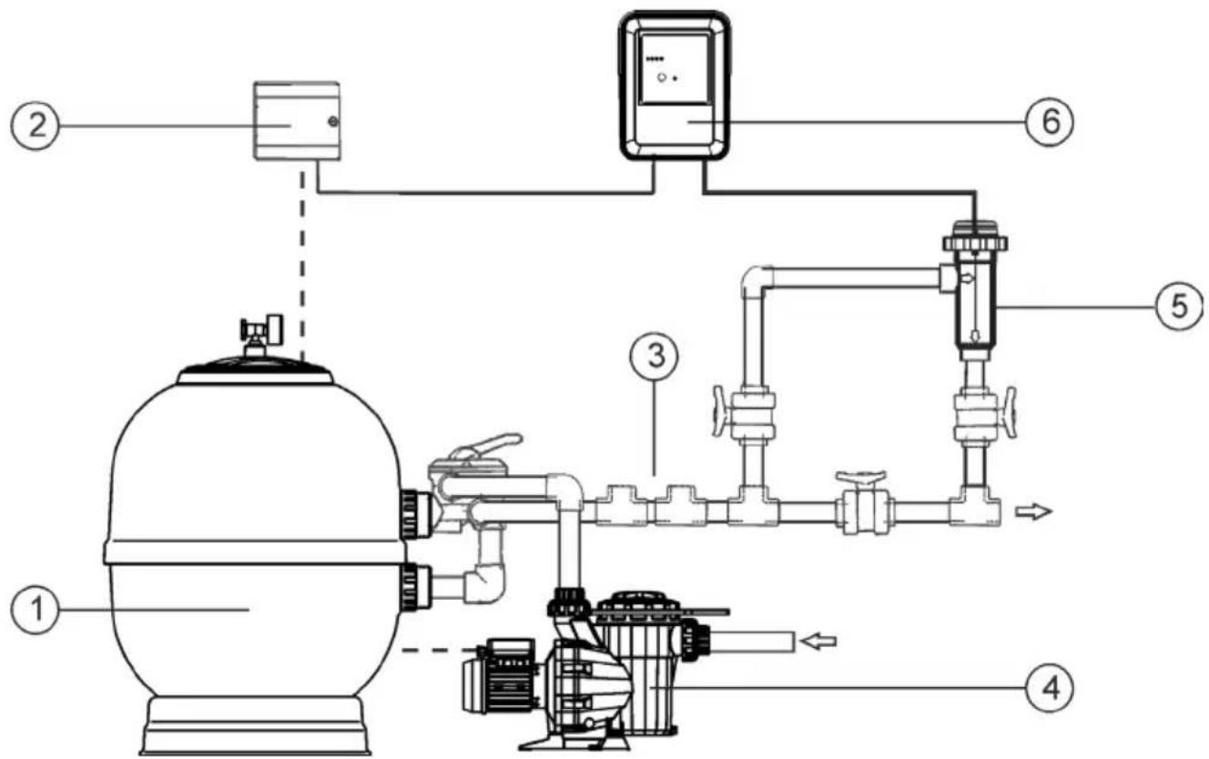
- Filter
4.- Pump.
-
- Switchbox
5.- Electrolysis cell
-
- Other equipment (heat exchanger, UV, etc.).
6.- Power supply
Fig.1 Recommended installation diagram.
4. INSTALLATION:
4.1. Installation of the power supply
Always install the POWER SUPPLY of the salt electrolysis system VERTICALLY on a solid and rigid surface (wall) as shown in the recommended installation diagram (Fig. 1). In order to guarantee a good state of conservation, the POWER SUPPLY should be installed in a well-ventilated dry place. Due to IP degree of the POWER SUPPLY the salt electrolysis system should not be installed outdoors. The POWER SUPPLY should be installed a bit distant from the electrolysis cell so that it cannot accidentally suffer water splashes.
Warning

Beware of corrosive atmosphere formation due to pH decreasing solution (specially, those ones based on hydrochloric acid "HCI"). Do not install the salt electrolysis system near to any stores of these chemicals. We strongly recommend the use of chemicals based on sodium bisulphate or diluted sulphuric acid. Power supply must be connected to the electrical control box of the pool, so that the pump and the salt electrolysis system are turned on (and off) simultaneously.
4.2. Installation of the electrolysis cell
The electrolysis cell is made of a transparent polymer in whose interior the electrodes are placed. The electrolysis cell must be always installed indoors and after the pool filter, and after any other equipment that may be present (heat pumps, control systems, etc.).
The installation of the cell should allow easy access to the installed electrodes by the user. It is highly recommended to install the electrolysis cell in a place of the pipe that can be easily isolated from the rest of the installation by two valves, so that the tasks of maintenance can be carried out with no need of partial or total draining of the swimming pool.
Where the cell is installed on a by-pass (recommended option), a valve to regulate the flow must be introduced. Prior to installation, please consider the following commentaries:
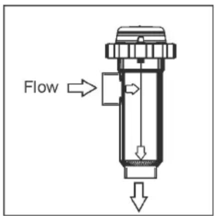
Fig. 2
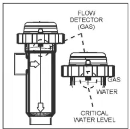
Fig. 3
natural_image
Pure schematic diagram of a piping system with valves and a warning symbol (no text or labels)Fig. 4
-
Flow direction marked in the cell must be respected. Recirculation system must guarantee the minimum flow stated in the Table of Technical Specifications for each model (see Section 8).
-
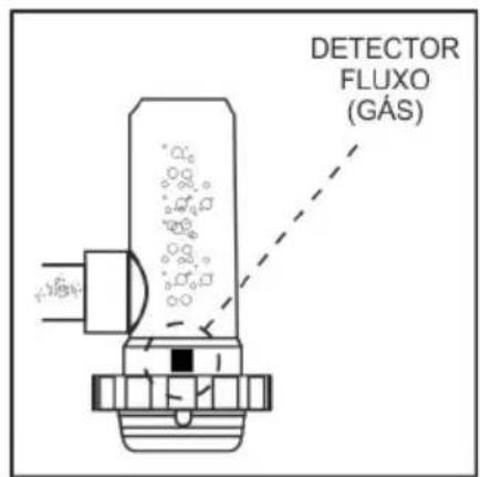
The system flow detector activates if there is not recirculation (flow) of water through the cell or if flow is very low. If electrolysis gases are not properly removed through the electrolysis cell, the generated gas bubble electrically isolates the auxiliary electrode (electronic detection). Therefore, when locating the electrodes in the cell, the level sensor (auxiliary electrode) will have to be located in the higher area of the cell. The safest orientation is shown in the recommended installation diagram.
-
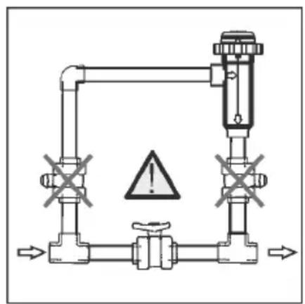
WARNING: if the in-out valves of the electrolysis cell are closed simultaneously, the flow detector (gas detector) will not work correctly, with the consequent risk of cell breakdown. Although this situation is extremely unusual, it can be easily avoided once the equipment has been installed, by locking at opened position the return valve to the swimming pool, so it cannot accidentally be manipulated.
Other configurations would only be acceptable in the case that they allow for detection of gas bubbles when water flow through the cell is too low.
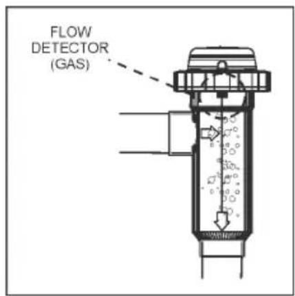
Fig. 5
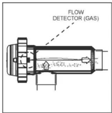
Fig. 6
RECOMMENDED Installation ALLOWABLE installation
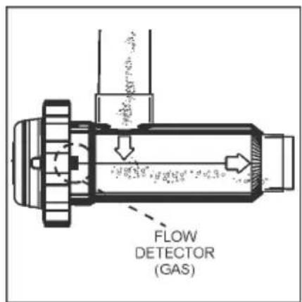
Fig. 7
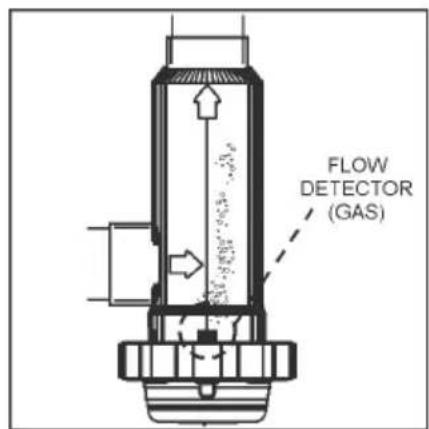
Fig. 8
4.3. Electrical connections of the electrolysis cell
Make the interconnection between the electrolysis cell and the power supply according to the following scheme. Due to relatively high current intensity circulating do not modify or cut either the length or section of the supplied cables without making a previous consultation to an authorized distributor. The cable connecting the electrolysis cell and the power supply should never exceed the maximum length recommended in this Manual: MOD.12 (6 A), 8 m.; MOD.21 (3.5 A), 30 m.
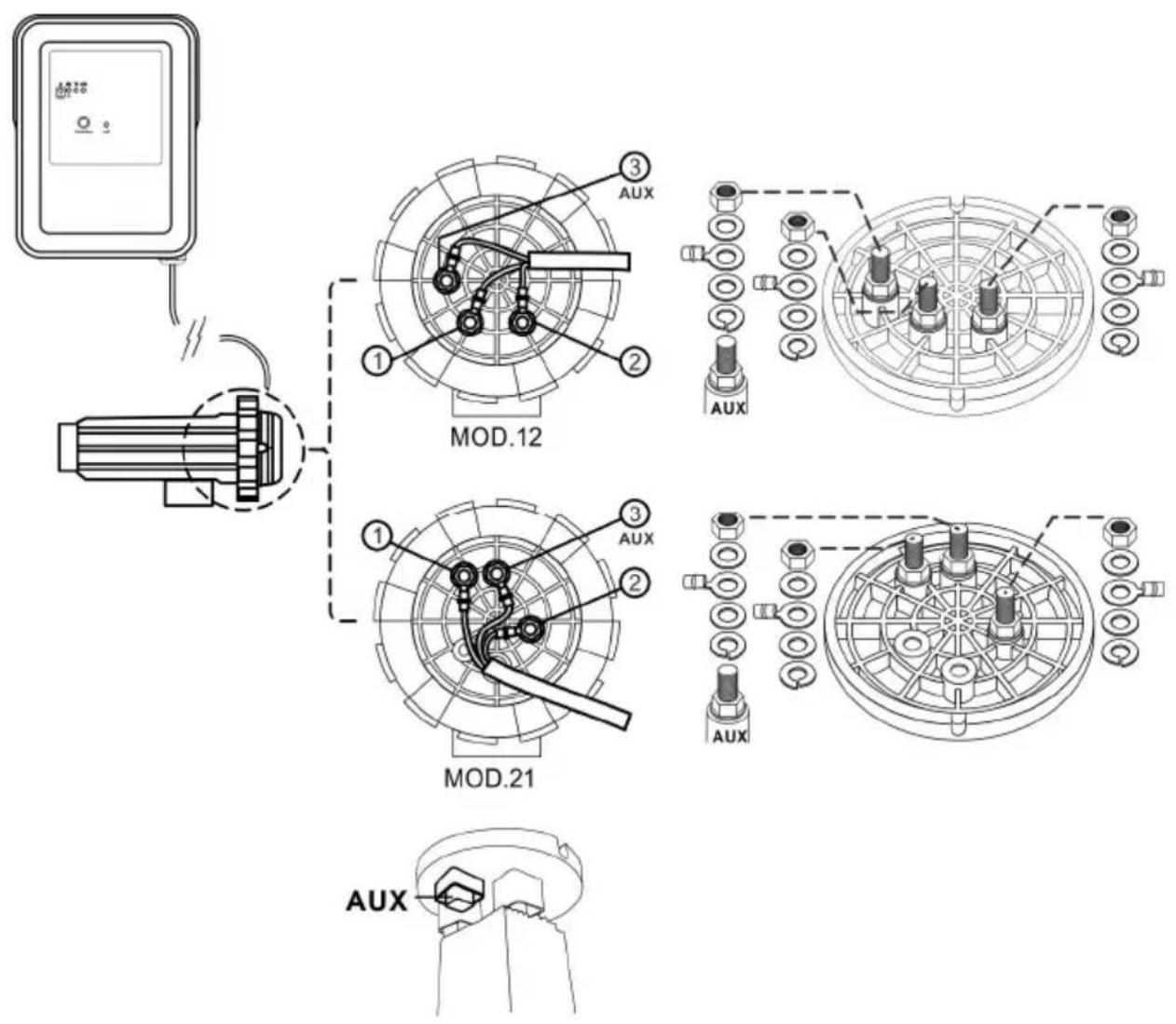
1.- Electrode 1 (Red)
2.- Electrode 2 (Red)
3.- Flow detector (Yellow)
Fig.9
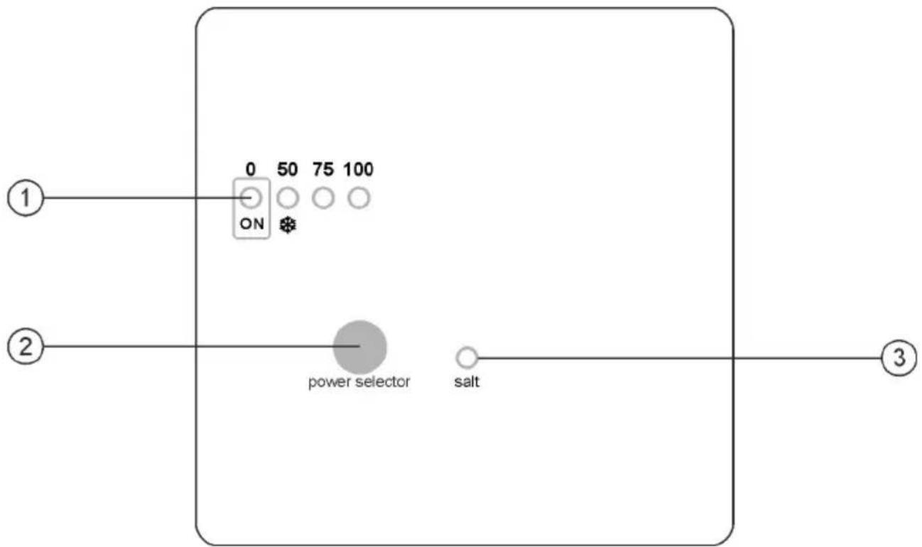
4.4. Controls and indicators
Salt electrolysis systems are equipped with a control panel in the front (Fig. 10).
other
Scale Production Range | Category | Value (%) | | :--- | :--- | | Stand-by | 0% 0...5% | | | 25% 5...35% | | | 50% 35...55% | | | 75% 55...80% | | | 100% 80...100% |2.- Production level selection key
3.- SALINITY ALARM (high/low)
Fig. 10. MOD. XX systems control panel.
4.5. Programming and control
Besides the basic operations, the salt electrolysis system has an input for an external control by means of an ORP controller, residual chlorine, etc.; as well as one for the adjustment of the production of the equipment on activation of the automatic swimming pool cover. Moreover, it permits the configuration of three electrode SELF-CLEANING modes: TEST, 2/2, 3/3 hours.
- ELECTRODE SELF-CLEANING System: The reversal frequency can be selected by means of jumper "JP1" on the system control panel (Fig. 11). This configuration will become effective by disconnecting and connecting again the equipment.
- AUTOMATIC COVER control: the system has an input for a potential-free contact. When the contact connected to this input is closed (automatic cover closed), the electrolysis system reduces its production to 10% of its rated value (the “50%” led of the production scale will blink).
- EXTERNAL Control: the system has an additional auxiliary input for a potential-free contact. This input can be used to make the electrolysis system interact with an external controller (ORP, RESIDUAL CHLORINE, PHOTOMETER, etc.). When the contact connected to this input is OPEN, the electrolysis system is stopped. To activate this input, place jumper "JP2" located on the unit's control panel. This configuration will become effective by disconnecting and connecting again the equipment.
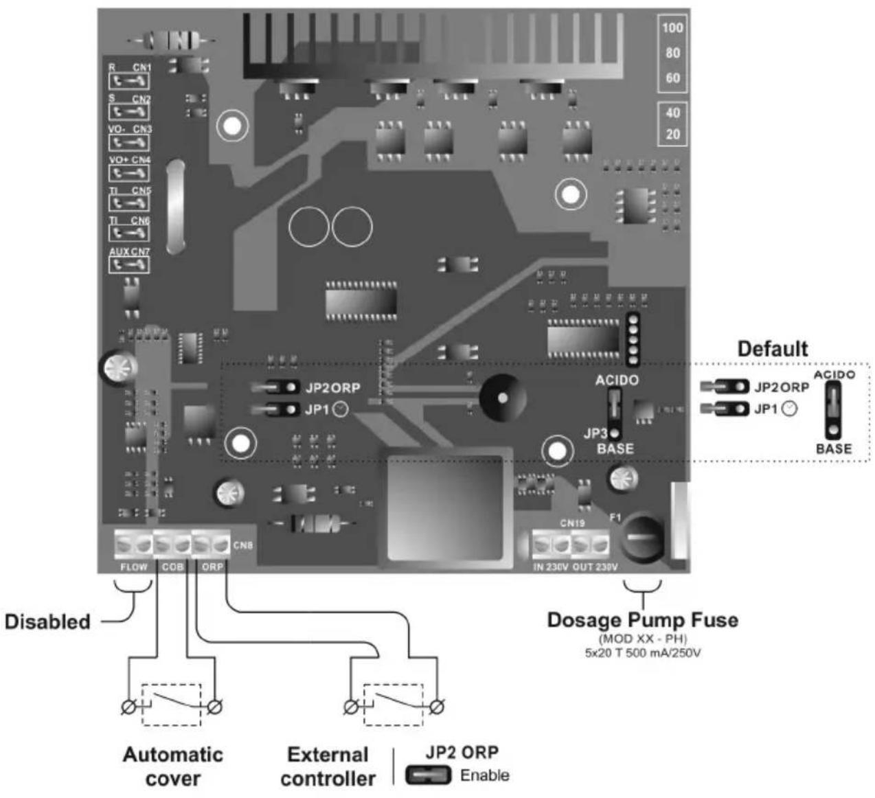
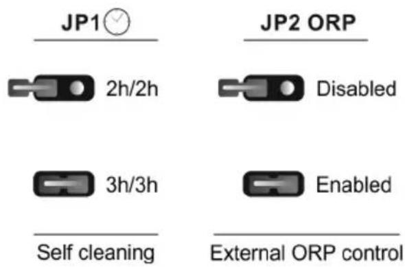
Fig. 11
4.6. Start-up
-
Check that the filter is 100% clean, and ensure that the swimming pool and the installation do not contain copper, iron or algae. Ensure that any heating equipment on the pool is suitable for use in salt water.
-
Ensure that the swimming pool water is balanced. Balanced water enables the chlorine that is produced to be used more efficiently and effectively, and ensures that the life of the electrodes is prolonged. Water should be maintained within the parameters shown below:
a) pH must be in the range 7.2-7.6
b) Total alkalinity must be in the range 80-120 ppm
-
Although the salt electrolysis system can work at a salinity range of 5 - 12 g/l, try to maintain the recommended minimum salt level of 6 g/l, by adding 6 kg per m ^3 of water if the water does not already contain salt. Always use common salt (sodium chloride), without additives like iodides, that is “apt for human consumption”. Never add the salt through the cell. Add it directly to the swimming pool or into the balance tank.
-
When adding the salt, and in case the swimming pool is going to be used immediately, carry out a treatment with chlorine. An initial dose of 2 g/m^3 of trichloroisocyanuric acid may be added.
-
Prior to starting up the salt chlorinator, disconnect the power supply to the salt chlorinator and run the pump for 24 hours to ensure that the salt is completely dissolved.
-
Next, reconnect the power supply and turn on the salt chlorinator, locating the production level so that free chlorine concentration stays within the recommended range (0.5 - 1.5 ppm).
NOTE: in order to establish the free chlorine level you will need to use a test kit.
- In outdoor swimming pools it is advisable to maintain a level of 25-30 g/m ^-3 of chlorine stabiliser (cyanuric acid) in the pool. A level of 75 ppm should be never exceeded. This will help to stop the chlorine that is in the water from being destroyed by the sun.
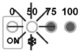
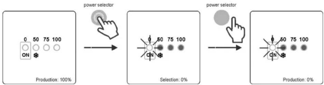
5. OPERATION:
5.1. System on stand-by
The system goes into "STAND-BY" when the POWER SELECTOR" [2] key is successively pressed until the "0%" light blinks. When this occurs, there is no production in the electrolysis cell.
flowchart
graph LR
    A["0 ON 50 75 100"] --> B["power selector"]
    B --> C["Selection: ON 50 75 100"]
    C --> D["power selector"]
    D --> E["Selection: CN 50 75 100"]
Fig. 12
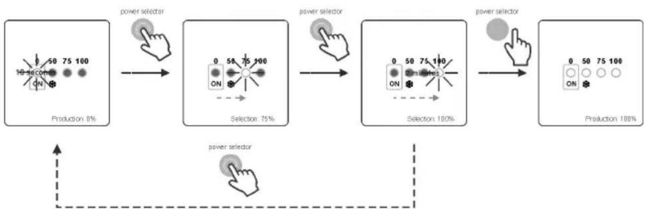
5.2. Production level selection
To select the desired production level, press the "POWER SELECTOR" [2] keys until the production level light blinks. The system will set its production to the desired level after a few seconds.
flowchart
graph LR
    A["10 seconds ON"] --> B["power selector"]
    B --> C["Selection: 75%"]
    C --> D["power selector"]
    D --> E["Selection: 100%"]
    E --> F["power selector"]
    F --> G["Production: 100%"]
Fig. 13
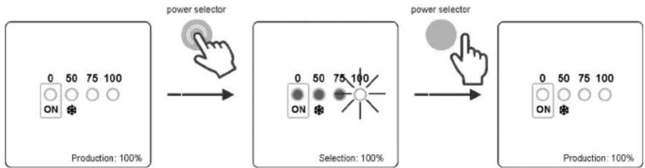
The production setpoint could be visualized at any time by pressing once the "POWER SELECTOR" [2] key.
The light corresponding to the programmed production level will blink for a few seconds. After this time the production scale will return to indicate the current production level.
flowchart
graph LR
    A["Production: 100% ON"] --> B["power selector"]
    B --> C["Selection: ON/OFF"]
    C --> D["power selector"]
    D --> E["Production: 100% ON/OFF"]
Fig. 14

WINTER Mode: during periods of low water temperature, where the chlorine demand will be low, select a production level [1] of 50%, because in this way power consumption and lifetime of the package of electrodes are optimized.
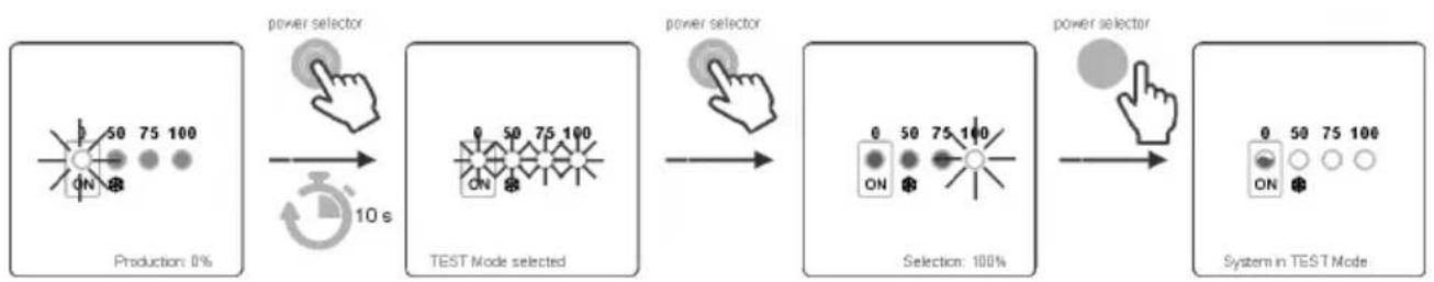
5.3. TEST Mode
To enter in TEST mode, lower the production level to "0%" successively pressing the "POWER SELECTOR" [2] key (Fig. 15).
Once the system has stopped, hold down this key for 10 seconds. The system will indicate that it has entered TEST MODE and all the leds will light up for one second.
Next select the desired production level through the "POWER SELECTOR" [2] key.
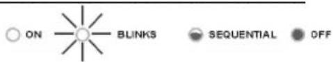
When the system is in TEST mode, the "0%" light will sequentially vary its intensity.
flowchart
graph LR
    A["Production: 0%"] --> B["power selector"]
    B --> C["10 s"]
    C --> D["TEST Mode selected"]
    D --> E["power selector"]
    E --> F["Selection: 100%"]
    F --> G["power selector"]
    G --> H["System in TEST Mode"]
Fig. 15
In TEST MODE, the system resets the polarity reversal timer and the output level selected. In this mode the system is fully operational, making polarity reversal of the electrodes every 2 minutes. To quit TEST MODE, the system must be switched off from the mains for a few seconds. Switching on the system again, it automatically returns to the previous self-cleaning program.
5.4. Alarms
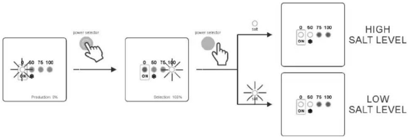
- HIGH SALT LEVEL
If too much salt has been added, the power supply will reduce the level of power with regard to that which was selected automatically. The “SALT” [3] led will stay on. In this case, empty part of the swimming pool (for example 10%), and add fresh water to reduce the salt concentration. To know the exact level of salt, we recommend the use of a portable salinity-temperature meter.
- LOW SALT LEVEL
If the level of salt in the swimming pools water were below the recommended level, the power supply may not reach the level of output selected. The "SALT" [3] led will blink. It is possible that the system indicates salt levels below the real ones if the water temperature is less than 20^ or if the electrode package has reached the end of its lifetime. In this case, determine the level of salt in the water and add the amount of salt needed. The type of common salt (NaCl) indicated for salt electrolysis should have no additives (anti-clogging agents, iodides) and should be suitable for human consumption. To know the exact level of salt we recommend the use of a portable salinity-temperature meter.
flowchart
graph LR
    A["Production: 0%"] --> B["power selector"]
    B --> C["Selection: 100%"]
    C --> D["power selector"]
    D --> E["salt"]
    D --> F["Low Salt Level"]
    style A fill:#f9f,stroke:#333
    style B fill:#ccf,stroke:#333
    style C fill:#cfc,stroke:#333
    style D fill:#fcc,stroke:#333
    style E fill:#ffc,stroke:#333
    style F fill:#fcc,stroke:#333
Fig. 16
• WATER LEVEL IN CELL/ FLOW DETECTOR (GAS)
If an air or gas bubble forms at any time at the top of the electrolysis cell and the FLOW DETECTOR is not submerged, the system will automatically switch off production and all of the leds of the control panel will blink. System automatically resets when water flows through the cell again or the bubble disappear.
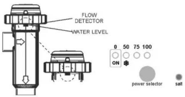
- Submerged gas detector. System running.
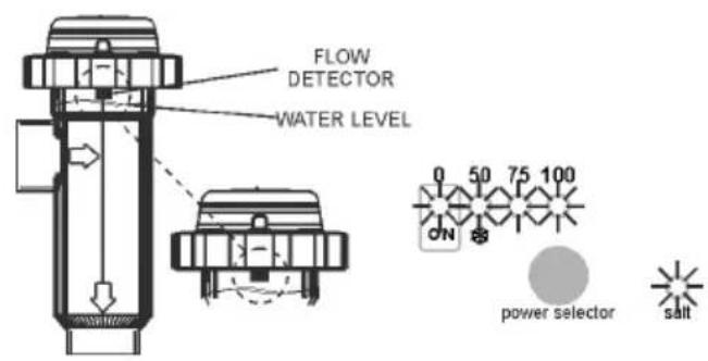
- Gas detected. Insufficient flow. System off.
Fig. 17
• EXTERNAL CONTROL [JP2] ACTIVATED
When the external controller detects a value over the fixed setpoint, it switches off production automatically and the "0%" led of the production scale [1] flashes.
6. MAINTENANCE:
6.1. Maintenance of the electrolysis cell
The electrolysis cell must be kept in suitable conditions to ensure a long lifetime. This salt chlorination unit has an automatic electrode cleaning system that helps to prevent scale build-up on the electrode surface. If the salt chlorination system is operated in accordance with these instructions, and in particular if the pool water balance is kept within the recommended parameters, it should not be necessary to manually clean the electrodes. However, if the pool water and the salt chlorination system are not maintained in line with these instructions then it may be necessary to manually clean the electrodes following the procedure outlined below:
- Cut off the 230 Vac unit's supply.
- Unscrew the closing nut located at the end where the electrodes are located, and remove the electrode package.
- Use diluted hydrochloric acid (a part of commercial acid in 10 parts of water), submerging the electrode package in the prepared solution for no more than 10 minutes.
- NEVER SCRAPE OR SWEEP THE CELL OR THE ELECTRODES.
The electrodes of a salt chlorination system comprise of a titanium sheet coated with a layer of noble metal oxides. The electrolysis processes that take place on their surface produce a progressive wearing down - the electrodes do have a finite life. In order to optimise electrode lifetime, please consider the following aspects:
- Although all salt electrolysis units are SELF-CLEANING, a prolonged operation of the system at pH values over 7.6 in waters of high hardness can produce scale formation on the surface of the electrodes. Scaling on the electrodes surface will progressively deteriorate the coating, causing a decrease of lifetime.
- Manually cleaning/washing the electrodes (as described above) will shorten their life.
- Prolonged operation of the system at salinities lower than 3 g/l (3000 ppm) will cause a premature deterioration of the electrodes.
- Frequent use of copper based algaecides will promote the formation of copper deposits on the electrodes, progressively damaging the coating. Remember that chlorine is the best algaecide.
7. TROUBLESHOOTING:
Any action required to solve possible problems in the equipment should always be performed with the equipment disconnected from the mains. Any problem not indicated in the following list should be solved by a qualified technician.
| PROBLEM SOLUTION | |
| Production indicator always indicates “0” at all production levels | Check the electrodes.Verify connections between power supply and the electrolysis cell.Check salt concentration. |
| It is not possible to turn on the power supply. | Check that the system is properly connected to 230 V/50-60 Hz in the control box of the pump.Check the estate of the fuse located at the bottom of the power supply. |
| Free chlorine levels in the water are very low. | Check that the system produces chlorine in pool jets.Verify that the water Chemicals parameters (pH, combined chlorine, isocyanuric acid, etc.) are correct.Increase filtering time.Add chlorine stabilizer (cyanuric acid) until a concentration of 25 - 30 g/m ^3 is achieved. |
8. TECHNICAL SPECIFICATIONS:
| TECHNICAL SPECIFICATIONS: | |
| Working voltage230V AC - 50/60 Hz.Cable:MOD. 12MOD. 21 | 3 × 1.0 mm^2, 2 m. 0.4 A0.4 A |
| FuseMOD. 12MOD. 21 | 2 AT (5x20 mm)2 AT (5x20 mm) |
| Cell voltageCableMOD. 12MOD. 21 | 3 × 2.5 mm^2, 2 m. 10.5 VDC / 6.0 A23.0 VDC / 3.5 A |
| ProductionMOD. 12MOD. 21 | 10 ... 12 g/h17 ... 21 g/h |
| Minimum recirculation flowMOD. 12MOD. 21 | 2 m^3/h 3 m^3/h |
| Electrode numberMOD. 12MOD. 21 | 57 |
| Net weight (including packaging)MOD. 12MOD. 21 | 6.5 Kg.8.5 Kg. |
| GENERAL FEATURES: |
| Control systemMicroprocessor.Membrane keypad with control keys and operation indication leds.Control I/O: 2 inputs (potential-free contact type) for monitoring the automatic cover and external controller (ORP, RESIDUAL CHLORINE, etc.).Cell output: production control.Salinity / Temperature range:5 - 12 g/l. / +15 - 40 °C.Self-cleaningAutomatic polarity reversalWorking temperatureFrom 0^ C to +.50°CCooling: natural convectionMaterialPower supply:○ ABSElectrolysis cell:○ Transparent methacrylate |
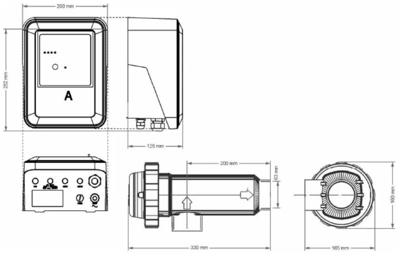
Dimensions
9. WARRANTY CONDITIONS:
9.1. GENERAL ASPECTS
9.1.1. According to these provisions, the seller guarantees that the guaranteed product is in perfect condition upon delivery.
9.1.2. The Total Warranty period is 2 YEARS.
9.1.3. The Warranty period will be calculated as of delivery to the purchaser. The electrode is covered by a 2-YEAR WARRANTY (or 3.000 hours), which is not extendable.
9.1.4. Should the Product be faulty and the seller is notified during the Guarantee Period, he shall repair or replace the Product at his own cost wherever he sees fit, unless this is either impossible or out of proportion.
9.1.5. When the Product cannot be repaired or replaced, the buyer may request a proportional price reduction or, if the fault is important enough, rescission of the sales contract.
9.1.6. Parts replaced or repaired pursuant to this warranty shall not extend the warranty period of the original Product, although they shall have their own warranty.
9.1.7. For this warranty to be effective, the buyer shall accredit the date of acquisition and delivery of the Product.
9.1.8. When the buyer alleges a fault in the product over six months after its delivery, he shall accredit the original and existence of the alleged fault.
9.1.9. This Warranty Certificate does not limit or prejudice consumer rights pursuant to national legislation.
9.2. SPECIFIC CONDITIONS
9.2.1. For this warranty to be effective, the buyer must closely follow the manufacturer's instructions included in the documentation supplied with the product, as applicable to each product range and model.
9.2.2. Whenever a schedule is defined for the replacement, maintenance or cleaning of certain product parts or components, the warranty shall only be valid when said schedule has been correctly followed.
9.3. LIMITATIONS
9.3.1. This warranty shall only be applicable to sales to consumers, with consumer being defined as a person who purchases the product for other than professional purposes.
9.3.2. No warranty is applicable to normal wear or the product, parts, components and/or fungible or consumable materials (except the electrode).
9.3.3. The warranty does not cover cases in which the product: (i) has been incorrectly treated; (ii) has been inspected, repaired, maintained or handled by an unauthorised person; (iii) has been repaired or maintained with non-original parts, or (iv) has been incorrectly installed or started up.
9.3.4. When a faulty product results from incorrect installation or start-up, this warranty shall only be applicable when the installation or start-up forms part of the product contract of sale and had been performed by the seller or under the seller's responsibility.
9.3.5. Damage or faults due to any of the following causes:
Operation at salinity values of less than 3 g of sodium chloride per liter and/or water temperature lower than 15°C or higher than 40°C.
○ Operation at a pH of more than 7.6.
- Use of non-explicitly authorised chemicals.
- Exposure to corrosive environments and/or ambient temperatures of less than 0°C or more than 50°C.
10. EC DECLARATION OF CONFORMITY
The following range of salt electrolysis systems are certified for swimming pool end use:
Certified products:
SCG60 (MOD.12), SCG100 (MOD.21).
The products listed above are in compliance with the following EC Directives and Standards:
○ Low Voltage Directive (LVD) 2014/35/UE.
○ Electromagnetic Compatibility Directive (EMC) 2014/30/UE.
- ROHS Directive 2011/65/EC
I.D. ELECTROQUIMICA, S.L.
Pol. Ind. Atalayas, c./ Dracma R-19
E-03114 Alicante
Spain
$$ f = x \int S $$
Gaspar Sánchez
General Manager
Date: 01/02/2017
natural_image
Symbol of a trash bin with crossed lines indicating no waste or discharge (no text or labels)1.- Filtro.
4.- Bomba.
natural_image
Pure schematic diagram of a piping system with valves and a warning symbol (no text or labels)Fig. 4
other
| Category | Value (%) | |---|---| | Sistema en espera | 0% 0...5% | | | 25% 5...35% | | | 50% 35...55% | | | 75% 55...80% | | | 100% 80...100% |I.D. ELECTROQUIMICA, S.L.
Pol. Ind. Atalayas, c./ Dracma R-19
E-03114 Alicante
España
$$ f = x \int S $$
Gaspar Sánchez Gerente
Fecha: 01/02/2017
natural_image
Symbol of a trash bin with crossed lines indicating no waste or discharge (no text or labels)3. MISES EN GARDE DE SÉCURITÉ ET RECOMMANDATIONS:
SOURCE D'ALIMENTATION:
natural_image
Warning symbol: black exclamation mark inside a triangle (no text or numbers)natural_image
Pure schematic diagram of a piping system with valves and a warning symbol (no text or labels)Fig. 4
Installation RECOMMANDÉE Installation ACCEPTABLE

Fig. 7
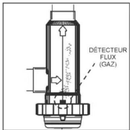
Fig. 8
other
| Category | Value (%) | |---|---| | Systeme arrêté | 0% 0...5% | | Top Panel | 25% 5...35% | | Bottom Panel | 50% 35...55% | | Bottom Panel | 75% 55...80% | | Bottom Panel | 100% 80...100% |I.D. ELECTROQUIMICA, S.L.
Pol. Ind. Atalayas, c./ Dracma R-19
E-03114 Alicante
Espagne
$$ f = x \int S $$
Gaspar Sánchez Gérant
Date: 01/02/2017
natural_image
Symbol of a trash bin with crossed lines indicating no waste or discharge (no text or labels)1.- Filter.
4.-Pumpe.
2.- Schalttafel.
- -Elektrolysezelle.
natural_image
Pure schematic diagram of a piping system with valve and valve symbols, no text or labels presentAbb. 4
1.- Produktionsskala (%)
other
| Category | Value (%) | |---|---| | Bereitschaft | 0% 0...5% | | | 25% 5...35% | | | 50% 35...55% | | | 75% 55...80% | | | 100% 80...100% |I.D. ELECTROQUIMICA, S.L.
Pol. Ind. Atalayas, c./ Dracma R-19
E-03114 Alicante
Spanien
$$ f = x \int S $$
Gaspar Sánchez
Geschäftsführer
Datum: 01/02/2017
natural_image
Symbol of a trash bin with crossed lines indicating no waste or discharge (no text or labels)natural_image
Warning symbol: black exclamation mark inside a triangle (no text or numbers)natural_image
Pure mechanical diagram showing pipe connections with a warning symbol (no text or labels)Fig. 4
Fig. 5
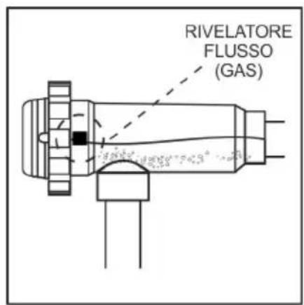
Fig. 6
Installazione RACCOMANDATA Instalación PERMSESSA
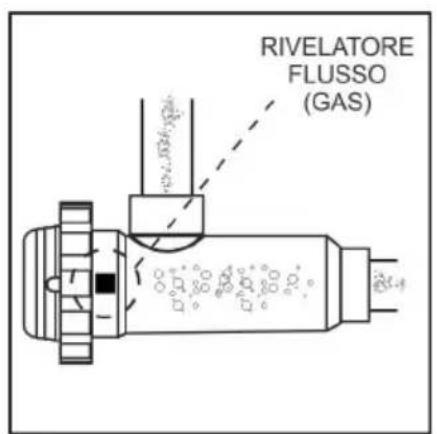
Fig. 7
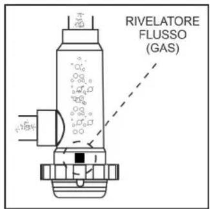
Fig. 8
I.D. ELECTROQUIMICA, S.L.
Pol. Ind. Atalayas, c./ Dracma R-19
E-03114 Alicante
España
$$ f = x \int S $$
Gaspar Sánchez
Manager
Data: 01/02/2017
natural_image
Symbol of a trash bin with crossed lines indicating no waste or discharge (no text or labels)Verwerking van elektrische en elektronische apparaten na hun levensduur (geldt enkel in de EU)
natural_image
Warning symbol: black exclamation mark inside a triangle (no text or numbers)natural_image
Pure diagram of industrial piping connections without any text, numbers, or symbolsFig. 4
other
| Category | Percentage (%) | | :--- | :--- | | Standby-systeem | 0% 0...5% | | | 25% 5...35% | | | 50% 35...55% | | | 75% 55...80% | | | 100% 80...100% |flowchart
graph LR
    A["ON"] --> B["Select: 0%"]
    C["ON"] --> D["Select: 0%"]
    E["ON"] --> F["Select: 0%"]
    G["ON"] --> H["Select: 0%"]
    I["ON"] --> J["Select: 0%"]
    K["ON"] --> L["Select: 0%"]
    M["ON"] --> N["Select: 0%"]
    O["ON"] --> P["Select: 0%"]
    Q["ON"] --> R["Select: 0%"]
    S["ON"] --> T["Select: 0%"]
    U["ON"] --> V["Select: 0%"]
    W["ON"] --> X["Select: 0%"]
    Y["ON"] --> Z["Select: 0%"]
    AA["ON"] --> AB["Select: 0%"]
    AC["ON"] --> AD["Select: 0%"]
    AE["ON"] --> AF["Select: 0%"]
    AG["ON"] --> AH["Select: 0%"]
    AI["ON"] --> AJ["Select: 0%"]
    AK["ON"] --> AL["Select: 0%"]
    AM["ON"] --> AN["Select: 0%"]
    AO["ON"] --> AP["Select: 0%"]
    AQ["ON"] --> AR["Select: 0%"]
    AS["ON"] --> AT["Select: 0%"]
    AU["ON"] --> AV["Select: 0%"]
    AW["ON"] --> AX["Select: 0%"]
    AY["Productie: 100%"] --> Z
    AZ["power selector"] --> AA
    BA["power selector"] --> AB
Fig. 12
I.D. ELECTROQUIMICA, S.L.
Pol. Ind. Atalayas, c./ Dracma R-19
E-03114 Alicante
España
$$ f = x \int S $$
Gaspar Sánchez
Gerente
Fecha: 01/02/2017
natural_image
Symbol of a trash bin with no text or labels1.- Filtro.
4.- Bomba.
natural_image
Warning symbol: black exclamation mark inside a triangle (no text or numbers)natural_image
Pure diagram of industrial piping connections without any text, numbers, or symbolsFig. 4
Fig. 7
I.D. ELECTROQUIMICA, S.L.
Pol. Ind. Atalayas, c./ Dracma R-19
E-03114 Alicante
España
$$ f = x \int S $$
Gaspar Sánchez Gerente
Data: 01/02/2017

natural_image
Circular logo with stylized 'Gre' text and abstract design, no readable text or symbols beyond the logo design.DISTRIBUTED BY / DISTRIBUIDO POR / DISTRIBUÉ PAR / VERTRIEB DURCH / DISTRIBUITO DA / DISTRIBUIDO POR: MANUFACTURAS GRE, S.A. ARITZ BIDEA N° 57 BELAKO INDUSTRIALDEA, APARTADO 69 - 48100 MUNGUIA (VIZCAYA) ESPAÑA N° Reg. Ind. 48-06762 MADE IN CHINA / FABRICADO EN CHINA / FABRIQUÉ AU CHINE / HERGESTELLT IN CHINA / PRODOTTO IN CHINA / FABRICADO NA RPC


- Instruction Manual - Manual de Instrucciones Manuel d'instructions - Bedienungsanleitung Manuale delle instruzioni - Handleiding met instructies Manual de instruções
- CHECK THE CONTENTS OF THE PACK:
- CARACTERISTICAS GENERALES:
- SAFETY WARNINGS AND RECOMMENDATIONS:
- INSTALLATION:
- Installation of the power supply
- Warning
- Installation of the electrolysis cell
- Electrical connections of the electrolysis cell
- Controls and indicators
- Programming and control
- Start-up
- OPERATION:
- System on stand-by
- Production level selection
- TEST Mode
- Alarms
- - HIGH SALT LEVEL
- - LOW SALT LEVEL
- • WATER LEVEL IN CELL/ FLOW DETECTOR (GAS)
- • EXTERNAL CONTROL [JP2] ACTIVATED
- MAINTENANCE:
- Maintenance of the electrolysis cell
- TROUBLESHOOTING:
- TECHNICAL SPECIFICATIONS:
- Dimensions
- WARRANTY CONDITIONS:
- GENERAL ASPECTS
- SPECIFIC CONDITIONS
- LIMITATIONS
- EC DECLARATION OF CONFORMITY
- MISES EN GARDE DE SÉCURITÉ ET RECOMMANDATIONS:
Brand : GRE
Model : SCG100
Category : Swimming Pool