625 - Measuring equipment Testo - Free user manual and instructions
Find the device manual for free 625 Testo in PDF.
| Product type | Temperature and humidity measuring device |
| Brand | Testo |
| Model | 625 |
| Measured quantities | Relative humidity (%), temperature (°C/°F) |
| Calculated quantities | Dew point temperature, wet bulb temperature |
| Humidity measurement range | 0 to +100 %RH (capacitive sensor) |
| Temperature measurement range (NTC sensor) | +10 to +60 °C / +14 to +140 °F |
| Temperature measurement range (type K thermocouple, telemetry) | -200 to +1370 °C / -328 to +2498 °F |
| Resolution | 0.1 %RH; 0.1 °C/°F |
| Humidity accuracy | ±2.5 %RH (from +5.0 to +95.0 %RH) |
| Temperature accuracy (NTC sensor) | ±0.5 °C / ±0.9 °F |
| Sensor | 1 plug-in sensor or telemetry sensor (accessory) |
| Measurement frequency | 2 measurements per second |
| Power supply | 1 9V battery or rechargeable battery (not rechargeable in the device) |
| Battery life (with sensor connected) | Approx. 70 hours |
| Operating temperature | -20 to +50 °C / -4 to +122 °F |
| Storage temperature | -40 to +85 °C / -40 to +185 °F |
| Protection type | IP65 (with TopSafe and sensor connected) |
| Warranty | 2 years |
| Display | Backlit display |
| Functions | Hold, Max/Min, humidity recalibration, auto-off, telemetry sensor detection |
| Maintenance | Clean the housing with a damp cloth (soapy water); replace battery/rechargeable battery |
| Safety | Do not use in explosive environments or for medical diagnostics; do not open except for maintenance |
| Accessories | Telemetry module, telemetry sensors, TopSafe, humidity module, etc. |
Frequently Asked Questions - 625 Testo
User questions about 625 Testo
0 question about this device. Answer the ones you know or ask your own.
Ask a new question about this device
Download the instructions for your Measuring equipment in PDF format for free! Find your manual 625 - Testo and take your electronic device back in hand. On this page are published all the documents necessary for the use of your device. 625 by Testo.
USER MANUAL 625 Testo
Humidity/temperature measuring instrument
General notes ....20
- Safety advice....21
- Intended purpose ....22
- Product description....23
3.1 Display and control elements .....23
3.2 Interfaces 24
3.3 Voltage supply 24
- Commissioning ....25
- Operation .....26
5.1 Connecting a probe ....26
5.2 Switching the instrument on / off 26
5.3 Switching the display light on / off .....27
5.4 Performing settings 27
- Measuring ....31
- Care and maintenance ....32
- Questions and answers....33
- Technical data ....34
- Accessories/spare parts ....35
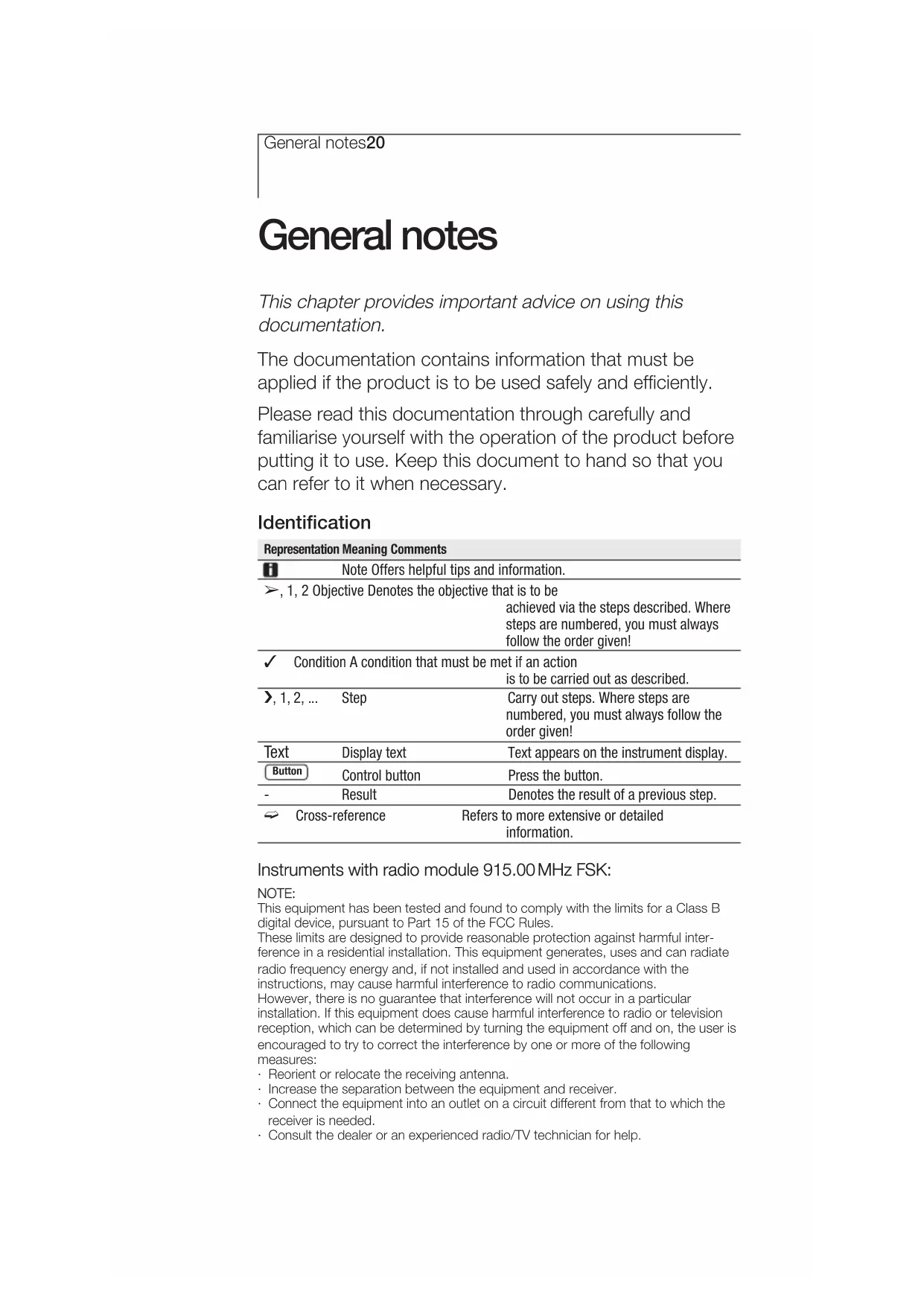
General notes
This chapter provides important advice on using this documentation.
The documentation contains information that must be applied if the product is to be used safely and efficiently.
Please read this documentation through carefully and familiarise yourself with the operation of the product before putting it to use. Keep this document to hand so that you can refer to it when necessary.
Identification
| Representation Meaning Comments | ||
| i | Note Offers helpful tips and information. | |
| ➢, 1, 2 Objective Denotes the objective that is to be achieved via the steps described. Where steps are numbered, you must always follow the order given! | ||
| ✓ Condition A condition that must be met if an action is to be carried out as described. | ||
| ➢, 1, 2, ... Step | Carry out steps. Where steps are numbered, you must always follow the order given! | |
| Text Display text | Text appears on the instrument display. | |
| Button Control button | Press the button. | |
| - Result | Denotes the result of a previous step. | |
| → Cross-reference | Refers to more extensive or detailed information. | |
Instruments with radio module 915.00 MHz FSK:
NOTE:
This equipment has been tested and found to comply with the limits for a Class B digital device, pursuant to Part 15 of the FCC Rules.
These limits are designed to provide reasonable protection against harmful interference in a residential installation. This equipment generates, uses and can radiate radio frequency energy and, if not installed and used in accordance with the instructions, may cause harmful interference to radio communications.
However, there is no guarantee that interference will not occur in a particular installation. If this equipment does cause harmful interference to radio or television reception, which can be determined by turning the equipment off and on, the user is encouraged to try to correct the interference by one or more of the following measures:
- Reorient or relocate the receiving antenna.
- Increase the separation between the equipment and receiver.
- Connect the equipment into an outlet on a circuit different from that to which the receiver is needed.
- Consult the dealer or an experienced radio/TV technician for help.
1. Safety advice
This chapter gives general rules which must be followed and observed if the product is to be handled safely.

Avoid personal injury/damage to equipment
Do not use the measuring instrument and probes to measure on or near live parts.
Never store the measuring instrument/probes together with solvents and do not use any desiccants.
Product safety/preserving warranty claims
Operate the measuring instrument only within the parameters specified in the Technical data.
Always use the measuring instrument properly and for its intended purpose. Do not use force.
Do not expose handles and feed lines to temperatures in excess of 70 °C unless they are expressly permitted for higher temperatures.
Temperatures given on probes / sensors relate only to the measuring range of the sensors.
Open the instrument only when this is expressly described in the documentation for maintenance and repair purposes.
Carry out only the maintenance and repair work that is described in the documentation. Follow the prescribed steps when doing so. For safety reasons, use only original spare parts from Testo.
Ensure correct disposal
Take faulty rechargeable batteries/spent batteries to the collection points provided for them.
Send the product back to Testo at the end of its useful life. We will ensure that it is disposed of in an environmentally friendly manner.
2. Intended purpose
This chapter gives the areas of application for which the product is intended.
Use the product only for those applications for which it was designed. Ask Testo if you are in any doubt.
testo 625 is a compact measuring instrument for measuring humidity and temperatures by means of a plug-in humidity/temperature probe (humidity module) and/or a humidity/temperature probe with radio transmission (radio module accessory part required).
The product was designed for the following tasks/applications:
• Measuring room climate
• Buildings, offices, warehouses
The product should not be used in the following areas:
- Areas at risk of explosion.
- Diagnostic measurements for medical purposes
3. Product description
This chapter provides an overview of the components of the product and their functions.

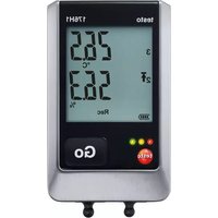
3.1 Display and control elements
Overview
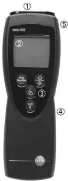
text_image
testo 625 ① ② ③ ④ ⑤① Probe socket
② Display
③ Control buttons
④ Battery compartment (rear)
⑤ Radio module and service compartment (rear)
Button functions
| Button Functions | |
| Switch instrument on;switch instrument off (press and hold) | |
| Switch display light on / off | |
| Hold / Max / Min | Keep reading, displaymaximum/minimum value |
| Open/leave configuration mode (pressand hold);In configuration mode:Confirm input | |
| In configuration mode:Increase value, select option | |
| In configuration mode:Reduce value, select option | |
| Change between displaying relativehumidity, dew point and wetbulbtemperature. | |
| Change between displaying connectedprobe and radio probe (lit). | |
3. Production description24
Important displays
| Display Meaning | |
| Battery capacity (bottom right in display): · 4 segments in the battery symbol are lit: Instrument battery is fully charged · No segments in the battery symbol are lit: Battery is almost spent | |
| Measurement channel: Radio probe (the number of “radio wave” segments shown indicates the strength of the signal) | |
| Battery capacity of radio probe (above the radio probe symbol Radio probe battery is almost spent | |
3.2 Interfaces
Probe socket
A plug-in measuring probe can be connected via the probe socket on the head of the instrument.
Radio module (accessory part)
i Radio probes may only be used in countries in which they have been Type Approved (see application information of the radio probe).
A radio measuring probe can be connected via the radio module.
3.3 Voltage supply
Voltage is supplied by means of a 9V monobloc battery (included in delivery) or rechargeable battery. It is not possible to run the instrument from the mains supply or charge a rechargeable battery in the instrument.
4. Commissioning
This chapter describes the steps required to commission the product.

➢ Removing the protective film on the display:
Pull the protective film off carefully.
➢ Inserting a radio module (accessory part):
i Radio probes may only be used in countries in which they have been Type Approved (see application information of the radio probe).
√ The instrument is switched off.
1 To open the radio module compartment on the rear of the instrument, push the clip lock downwards and remove the lid of the radio module compartment.
2 Insert the radio module.
3 To close the radio module compartment, replace the radio module compartment lid and close it.
- Inserting a battery/rechargeable battery:
1 To open the battery compartment on the rear of the instrument, push the lid of the battery compartment in the direction of the arrow and remove it.
2 Insert a battery/rechargeable battery (9V monobloc). Observe the polarity!
3 To close the battery compartment, replace the lid of the battery compartment in position and push it against the direction of the arrow.
5. Operation26
5. Operation
This chapter describes the steps that have to be executed frequently when using the product.
5.1 Connecting a probe
Plug-in probes
Plug-in probes must be connected before the measuring instrument is switched on so that they are recognised by the instrument.
Insert the connector of the probe into the probe socket.
Radio probes
i Radio probes may only be used in countries in which they have been Type Approved (see application information of the radio probe).
A radio module (accessory part) is required for the use of radio probes. The radio module must be connected before the measuring instrument is switched on so that it is recognised by the instrument.
Each radio probe has a probe ID (identification number). This must be set in configuration mode.
→ See the chapter PERFORMING SETTINGS.
5.2 Switching the instrument on / off
▶ Switching the instrument on:
Press
- Measurement view is opened: The current reading is displayed, or ---- lights up if no reading is available.
▶ Switching the instrument off:
Press and hold (for approx. 2s) until the display goes out.
5.3 Switching the display light on / off
▶ Switching the display light on/off:
√ The instrument is switched on.
Press※.
5.4 Performing settings
1 To open configuration mode:
√ The instrument is switched on and is in measurement view. Hold, Max or Min are not activated.
Press and hold (for approx. 2s) until the display changes.
- The instrument is now in configuration mode.
You can change to the next function with 📄 You can leave configuration mode at any time. To do so, press and hold (for approx. 2s) until the instrument has changed to measurement view. Any changes that have already been made in configuration mode will be saved.
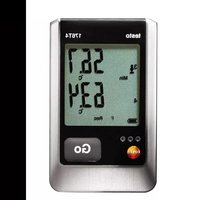
2 Carrying out a humidity calibration:
A 2-point calibration of connected humidity probes can be carried out (11.3%RH and 75.3%RH).
√ Configuration mode is opened, CAL is lit.
1 Select the desired option with △ / ▽ and confirm with ←:
- oFF: Humidity calibration is not carried out.
· on: Humidity calibration is carried out.
oFF was selected:
Continue with objective To REGISTER THE RADIO PROBE.
5. Operation28
on was selected:
2 Put the humidity probe into the reference medium and wait for the equalisation period to elapse.
- The current humidity reading and the calibration point (nominal value) are displayed.
3 Start the calibration menu with .
4 Select the desired option with △ / ▽ and confirm with ←:
- no: Humidity value is not calibrated.
- YES: Humidity value is calibrated.
no was selected:
Continue with objective To REGISTER THE RADIO PROBE.
YES was selected:
- The calibration is carried out.
5 Repeat steps 2 to 4 for the 2^nd calibration point.
- When calibration has been completed, the instrument changes to the next setting function.
3 To register the radio probe:
i Radio probes may only be used in countries in which they have been Type Approved (see application information of the radio probe).
The setting function for radio probes is only available if a radio module (accessory part) is inserted into the measuring instrument.
→ See the chapter COMMISSIONING.
If no radio module is inserted:
→ Continue with the objective To SET AUTO OFF.
Each radio probe has a probe ID (RF ID). This consists of the last 3 digits of the serial no. and the position of the slide switch in the radio probe (H or L).
√ Configuration mode is opened, is flashing and AUTO is lit.
√ The radio probe is switched on and the transfer rate is set to 2 readings per second (see the advice on using the radio probe).
1 Select the desired option with and confirm with

- YES: Switches automatic probe detection on (recommended).
· no: Switches automatic probe detection off.
no was selected:
2 Use /to set the probe ID manually and confirm with
Continue with objective To SET AUTO OFF.
YES was selected:
- Automatic probe detection is started.
- Once a radio probe is found, the probe ID is displayed. If no probe is found, NONE lights up.
If more than one radio probe is switched on:
If necessary, select the desired probe with △. ▼
Possible causes why probes are not found:
- The radio probe is not switched on or the battery of the radio probe is spent.
- The radio probe is outside the range of the measuring instrument.
- Sources of interference are influencing the radio transmission (e.g. reinforced concrete, metal objects, walls or other barriers between transmitter and receiver, other transmitters of the same frequency, strong electromagnetic fields).
If necessary, rectify the possible causes for the disruption to the radio transmission and start configuration mode again.
2 Press to change to the next function.

5. Operation30
4 To set Auto Off:
√ Configuration mode is opened, AutoOff is flashing.
Select the desired option with △ / ▽ and confirm with ←:
- on: The measuring instrument switches off automatically if no button is pressed for 10min (Hold or Auto Hold is lit).
- oFF: The measuring instrument does not switch itself off automatically.
5 To set the unit of measurement:
√ Configuration mode is opened, UNIT is lit.
Select the desired unit of measurement with △ and confirm with ▶
6 To reset:
√ Configuration mode is opened, RESET is lit.
Select the desired option with △ and ▽ confirm with ←:
- no: Instrument is not reset.
- Yes: Instrument is reset. The instrument is reset to the factory settings.
- The instrument returns to measurement view.
6. Measuring
This chapter describes the steps that are required to perform measurements with the product.
en
▶ Taking a measurement:
√ The instrument is switched on and is in measurement view.
Put the probe in position and read off the readings.
➢ Changing the measurement channel display:
To change between displaying the connected probe and the radio probe ( ). Press .
To change between displaying relative humidity (%), the calculated dew point temperature (td °C, below 0°Ctd/32°Ftd frost point temperatures are displayed) and the calculated wetbulb temperature (wetbulb): Press 🔒.
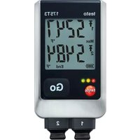
➢ Holding the reading, displaying the maximum/minimum value:
The current reading can be recorded. The maximum and minimum values (since the instrument was last switched on) can be displayed.
Press Several times until the desired value is displayed.
- The following are displayed in turn:
- Hold: the recorded reading
- Max: Maximum value
- Min: Minimum value
• The current reading
➢ Resetting the maximum/minimum values:
The maximum/minimum values of all channels can be reset to the current reading.
1 Press Hold / Max / Min several times until Max or Min lights up.
2 Press and hold Hold / Max / Min (approx. 2s).
- All maximum or minimum values are reset to the current reading.
7. Care and maintenance
This chapter describes the steps that help to maintain the functionality of the product and extend its service life.
▶ Cleaning the housing:
Clean the housing with a moist cloth (soap suds) if it is dirty. Do not use aggressive cleaning agents or solvents!
➢ Changing the battery/rechargeable battery:
√ The instrument is switched off.
1 To open the battery compartment on the rear of the instrument, push the lid of the battery compartment in the direction of the arrow and remove it.
2 Remove the spent battery/rechargeable battery and insert a new battery/rechargeable battery (9 V monobloc). Observe the polarity!
3 To close the battery compartment, replace the lid of the battery compartment in position and push it against the direction of the arrow.
8. Questions and answers
This chapter gives answers to frequently asked questions.

| Question Possible causes Possible solution | ||
| is lit (bottom right · Instrument battery is · Replace instrument in display). almost spent. battery.is lit (above · Radio probe battery · Replace radio probe symbol). is almost spent. battery. | ||
| Instrument switches itself off automatically. | · Auto Off function is switched on. · Residual capacity · Replace battery. of battery is too low. | · Switch function off. |
| Display: ---- | · Probe is not plugged in. · Registered probe was not found. · Probe break. | · Switch instrument off, connect probe and switch instrument back on again. · Register radio probe again, see chapter PERFORMING SETTINGS, objective TO REGISTER THE RADIO PROBE. · Please contact your dealer or Testo Customer Service. |
| Display reacts slowly · Ambient temperature is very low. | · Raise ambient temperature. | |
| Display: uuuuu | · Permitted measuring range was undershot. | · Keep to permitted measuring range. |
| Display: 00000 | · Permitted measuring range was exceeded. | · Keep to permitted measuring range. |
If we are unable to answer your question, please contact your dealer or Testo Customer Service. Contact details can be found on the guarantee card or on the Internet under www.testo.com.
9. Technical data34
9. Technical data
| Characteristic Value | |
| Parameters Relative humidity (%), temperature (°C/°F) | |
| Calculated variables Dew point temperature (°Ctd/°Ftd), wet bulb temperature (wetbulb °C/wetbulb °F) | |
| Measuring range Testo humidity probe, capacitive: 0...+100%RH NTC probe: -10...+60°C / +14...+140°F Type K (NiCr-Ni) probe (radio probe): -200...+1370°C / -328...+2498°F | |
| Resolution 0.1%RH 0.1°C / 0.1°F | |
| Accuracy Testo humidity probe, capacitive: (±1 Digit) ±2.5%RH (+5.0...+95.0%RH) NTC probe: ±0.5°C / ±0.9°F Type K (NiCr-Ni) probe (radio probe): depends on probe | |
| Probe Socket for humidity module, radio module (accessory part) | |
| Measuring rate 2/s | |
| Operating temperature range -20...+50°C / -4...+122°F | |
| Storage temperature -40...+85°C / -40...+185°F | |
| Voltage supply | 1x 9V monobloc battery/rech. battery |
| Battery life | with probe connected: approx. 70h |
| Protection class | with TopSafe (acc. part) and humidity module connected: IP65 |
| EC Directive | 89/336/ECC |
| Warranty | 2 years |
10. Accessories/spare parts
en
| Name Part no. | |
| Radio modules1 | |
| Radio module 869.85MHz, authorisation for e. g. DE, ES, IT, FR, GB | 0554 0188 |
| Radio module 915.00MHz, authorisation for e. g. USA 0554 0190 | |
| Radio probes1 | |
| Radio immersion/penetration probe, NTC, authorisation for e. g. DE, ES, IT, FR, GB | 0613 1001 |
| Radio immersion/penetration probe, NTC, authorisation for e. g. USA 0613 1002 | |
| Universal radio handles | |
| Radio handle for plug-in probeheads incl. TC adapter, authorisation for e. g. DE, ES, IT, FR, GB | 0554 0189 |
| Radio handle for plug-in probeheads incl. TC adapter, authorisation for e. g. USA 0554 0191 | |
| Adapter for connection to TC probes on radio handle 0554 0222 | |
| TC -probehead for air/immersion tip, attachable to radio handle 0602 0293 | |
| Humidity/temperature probes | |
| Plug-in humidity-probehead for testo 625 and radio handle 0636 9725 | |
| Handle for Plug-in humidity-probehead, for connection to measuring instrument, includes probe cable, measures/adjusts humidity probe 0430 9725 | |
| Miscellaneous | |
| TopSafe testo 625, protects from impact and dirt particles | 0516 0221 |
^1 Radio probes may only be used in countries in which they have been Type Approved (see application information of the radio probe).
For a complete list of all accessories and spare parts, please refer to the product catalogues and brochures or look up our website: www.testo.com
testo 625