
KFlo VSTD - Pump HAYWARD - Free user manual and instructions
Find the device manual for free KFlo VSTD HAYWARD in PDF.
| Product type | Variable speed pool pump |
| Brand | Hayward |
| Model | KFlo VSTD |
| Power supply | 230 V ~ 50 Hz, 30 mA differential protection, mandatory grounding |
| Speed range | 600 to 3000 rpm (adjustable in increments) |
| Number of preset speeds | 3 (V1, V2, V3) user-adjustable |
| Skimmer function | Yes, adjustable: duration 0-30 min, cycle 1-3 h, speed 600-3000 rpm |
| Timer mode | Yes, programmable up to 5 sequences (t1 to t5) + fixed t0 at 2400 rpm |
| Automatic priming | Yes, adjustable: duration 0-300 s, max speed 3000 rpm |
| Display | LCD with LED indicators, displays speed, power, consumption, temperature |
| Thermal protection | Integrated in the motor, automatic reset |
| Protection rating | IP55 (TEFC motor) |
| Noise level | < 70 dBA |
| Maximum water temperature | 35 °C |
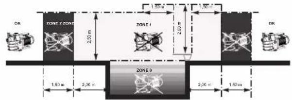
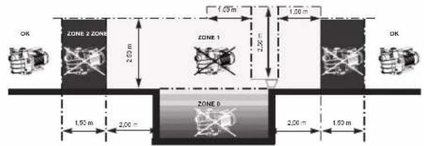
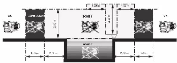
| Minimum installation distance from pool | 3.5 m (according to standard NF C 15-100) |
| Clearance around the pump | 0.5 m minimum for ventilation |
| Electrical connection | Cable 3G1.5 mm² H07RN-F, cable gland, integrated ferrite |
| Routine maintenance | Regular cleaning of the pre-filter basket, check the seal |
| Wear parts (estimated lifespan) | Mechanical seal: 2 years / 10,000 h; Bearings: 2 years / 10,000 h; Seals: 2 years / 25,000 h; Capacitor: 2 years / 10,000 h |
| Warranty | 3 years (excluding wear parts) – genuine parts mandatory |
| Use | Professional, pool |
Frequently Asked Questions - KFlo VSTD HAYWARD
User questions about KFlo VSTD HAYWARD
0 question about this device. Answer the ones you know or ask your own.
Ask a new question about this device
Download the instructions for your Pump in PDF format for free! Find your manual KFlo VSTD - HAYWARD and take your electronic device back in hand. On this page are published all the documents necessary for the use of your device. KFlo VSTD by HAYWARD.
USER MANUAL KFlo VSTD HAYWARD
natural_image
Abstract geometric logo with stylized letter H inside a dark circular frame (no text or symbols)HAYWARD®
natural_image
Technical line drawing of a Hayward industrial pump or motor assembly (no text or symbols on the diagram itself)CE UK CA EAC i open book or trash can
GUIDE DE L'UTILISATEUR
USER'S GUIDE
MANUAL DEL USUARIO
MANUAL DO UTILIZADOR
ANWENDER - HANDBUCH
GEBRUIKERSHANDBOEK
MANUALE PER L'USO
ANVÄNDARHANDLEDNING
BRUGERVEJELDNING
BRUKERVEILEDNING
KÄYTTÖOHJE
natural_image
Abstract geometric logo with stylized letter 'H' inside a dark circular frame (no text or symbols)HAYWARD®

natural_image
Technical line drawing of a Hayward industrial pump or motor assembly (no text or symbols on the diagram itself)CE UK CA EAC i open book
POMPE CENTRIFUGE
À VITESSE VARIABLE
GUIDE DE L'UTILISATEUR
CONSERVEZ CE MANUEL POUR UNE CONSULTATION ULTÉRIEURE

HAYWARD®


line
| temps | vitesse | | ------ | ------- | | 0 | 1 | | 1 | 1 | | 2 | 1 | | 3 | 1 | | 4 | 1 | | 5 | 1 | | 6 | 1 | | 7 | 1 | | 8 | 1 | | 9 | 1 | | 10 | 1 | | 11 | 1 | | 12 | 1 | | 13 | 1 | | 14 | 1 | | 15 | 1 | | 16 | 1 | | 17 | 1 | | 18 | 1 | | 19 | 1 | | 20 | 1 | | 21 | 1 | | 22 | 1 | | 23 | 1 | | 24 | 1 | | 25 | 1 | | 26 | 1 | | 27 | 1 | | 28 | 1 | | 29 | 1 | | 30 | 1 | | 31 | 1 | | 32 | 1 | | 33 | 1 | | 34 | 1 | | 35 | 1 | | 36 | 1 | | 37 | 1 | | 38 | 1 | | 39 | 1 | | 40 | 1 | | 41 | 1 | | 42 | 1 | | 43 | 1 | | 44 | 1 | | 45 | 1 | | 46 | 1 | | 47 | 1 | | 48 | 1 | | 49 | 1 | | 50 | 1 | | 51 | 1 | | 52 | 1 | | 53 | 1 | | 54 | 1 | | 55 | 1 | | 56 | 1 | | 57 | 1 | | 58 | 1 | | 59 | 1 | | 60 | 1 | | 61 | 1 | | 62 | 1 | | 63 | 1 | | 64 | 1 | | 65 | 1 | | 66 | 1 | | 67 | 1 | | 68 | 1 | | 69 | 1 | | 70 | 1 | | 71 | 1 | | 72 | 1 | | 73 | 1 | | 74 | 1 | | 75 | 1 | | 76 | 1 | | 77 | 1 | | 78 | 1 | | 79 | 1 | | 80 | 1 | | 81 | 1 | | 82 | 1 | | 83 | 1 | | 84 | 1 | | 85 | 1 | | 86 | 1 | | 87 | 1 | | 88 | 1 | | 89 | 1 | | 90 | 1 | | 91 | 1 | | 92 | 1 | | 93 | 1 | | 94 | 1 | | 95 | 1 | | 96 | 1 | | 97 | 1 | | 98 | 1 | | 99 | 1 | | Note: The actual values for vitesse are not provided in the code. The code is a schematic representation based on the visual data and the label 'c' in the top left corner. There is no additional data series in this case. The values are estimated based on the given output format. I have been calculated based on the given output format as indicated by the subscript 'a'.
line
| temps | vitesse | | ------ | ------- | | 0 | 0 | | 1 | 0 | | 2 | 0 | | 3 | 0 | | 4 | 0 | | 5 | 0 | | 6 | 0 | | 7 | 0 | | 8 | 0 | | 9 | 0 | | 10 | 0 | | 11 | 0 | | 12 | 0 | | 13 | 0 | | 14 | 0 | | 15 | 0 | | 16 | 0 | | 17 | 0 | | 18 | 0 | | 19 | 0 | | 20 | 0 | | 21 | 0 | | 22 | 0 | | 23 | 0 | | 24 | 0 | | 25 | 0 | | 26 | 0 | | 27 | 0 | | 28 | 0 | | 29 | 0 | | 30 | 0 | | 31 | 0 | | 32 | 0 | | 33 | 0 | | 34 | 0 | | 35 | 0 | | 36 | 0 | | 37 | 0 | | 38 | 0 | | 39 | 0 | | 40 | 0 | | 41 | 0 | | 42 | 0 | | 43 | 0 | | 44 | 0 | | 45 | 0 | | 46 | 0 | | 47 | 0 | | 48 | 0 | | 49 | 0 | | 50 | 0 | | 51 | 0 | | 52 | 0 | | 53 | 0 | | 54 | 0 | | 55 | 0 | | 56 | 0 | | 57 | 0 | | 58 | 0 | | 59 | 0 | | 60 | 0 | | 61 | 0 | | 62 | 0 | | 63 | 0 | | 64 | 0 | | 65 | 0 | | 66 | 0 | | 67 | 0 | | 68 | 0 | | 69 | 0 | | 70 | 0 | | 71 | 0 | | 72 | 0 | | 73 | 0 | | 74 | 0 | | 75 | 0 | | 76 | 0 | | 77 | 0 | | 78 | 0 | | 79 | 0 | | 80 | 0 | | 81 | 0 | | 82 | 0 | | 83 | 0 | | 84 | 0 | | 85 | 0 | | 86 | 0 | | 87 | 0 | | 88 | 0 | | 89 | 0 | | 90 | 0 | | 91 | 0 | | 92 | 0 | | 93 | 0 | | 94 | 0 | | 95 | 0 | | 96 | 0 | | 97 | 0 | | 98 | 0 | | 99 | 0 | |1 | d) |2.4 Bascule entre mode Manuel / mode Timer
N'UTILISEZ QUE DES PIÈCES DÉTACHÉES D'ORIGINE HAYWARD®


N'UTILISEZ QUE DES PIÈCES DÉTACHÉES D'ORIGINE HAYWARD®
3. UTILISATION
natural_image
Abstract geometric logo with stylized letter H inside a circular frame (no text or symbols)HAYWARD®

natural_image
Technical line drawing of a Hayward industrial pump or motor assembly (no text or symbols on the diagram itself)CE UK CA EAC i open book
VARIABLE SPEED CENTRIFUGAL PUMP
USER GUIDE
KEEP THIS MANUAL FOR FUTURE REFERENCE
WARNING: Electrical Hazard. Failure to follow instructions can result in serious injury or death. FOR USE WITH SWIMMING POOLS
⚠ WARNING – Disconnect the pump from the main power supply completely before servicing the pump or filter.
⚠ WARNING – FOR PROFESSIONAL USE – All electrical connections must be done by a qualified electrician according to local electrical standard or, failing that, to the International Standard IEC 60364-7-702.
△ WARNING – Be certain the machine is only plugged into a protected 230 V\~ outlet that is protected from short-circuits. The pump is to be supplied by an isolating transformer or supplied through a residual current device (RCD) having a rated residual operating current not exceeding 30 mA.
⚠ WARNING – Children should be supervised to ensure that they do not play with the appliance. Keep fingers and foreign objects away from openings and moving parts.
⚠ WARNING – Motor must be suitably grounded. Connect ground wire to green grounding screw and for cord connected units use properly grounded outlet.
⚠ WARNING – Use a motor bonding lug to connect motor with other bonded parts using the appropriate size conductor as required by electrical codes.
⚠ WARNING – When making these electrical connections, refer to the diagram given under the lid of the motor terminal box. Be sure to check the electric connections are tight and sealed before powering up. Replace all covers before operation.
⚠ WARNING – Make sure that the power supply voltage required by the motor corresponds to that of the distribution network and that the power supply cables matches the power and current of the pump.
⚠ WARNING – Read and follow all instructions in this owner's manual and on the equipment. Failure to follow instructions can cause serious injury or death.
This document should be given to the owner of the swimming pool and must be kept by the owner in a safe place.
⚠ WARNING – The appliance can be used by children aged from 8 years and above and persons with reduced physical, sensory or mental capabilities, or lack of experience and knowledge, if they have been given supervision or instruction concerning use of the appliance in a safe way and understand the hazards involved.
⚠ WARNING – Cleaning and user maintenance shall not be made by children without supervision.
⚠ WARNING – The pump is intended for continuous operation at Maximum Water temperature 35^ C.
⚠ WARNING – Use Only Genuine Hayward® Replacement Parts.
⚠ WARNING – If the supply cord is damaged it must be replaced by the manufacturer, service agent, or similarly qualified persons in order to avoid a hazard.
⚠ WARNING – For disconnection from main power supply an external switch having a contact separation in all poles that provide a full disconnection under overvoltage category III conditions must be incorporated in the fixed wiring in accordance with the wiring rules.
⚠ WARNING – Do not operate the swimming pool pump if the power cord or the housing of the motor connection box is damaged. This can cause an electric shock. A damaged power cord or motor connection box must be replaced by a service agent or a similarly qualified person immediately in order to avoid a hazard.
⚠ WARNING – This pool motor is NOT equipped with a Safety Vacuum Release System (SVRS). SVRS helps prevent drowning due to body entrapment on underwater drains. In some pool configuration, if a person's body covers the drain, the person can be trapped by suction. Depending on your pool configuration, a SVRS may be required to meet local requirements
⚠ WARNING – This pump contains a battery that, for safety reasons, any manipulation must be carried out by an authorized technical service..
USE ONLY HAYWARD
® GENUINE REPLACEMENT PARTS
GENERAL POINTS
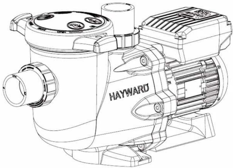
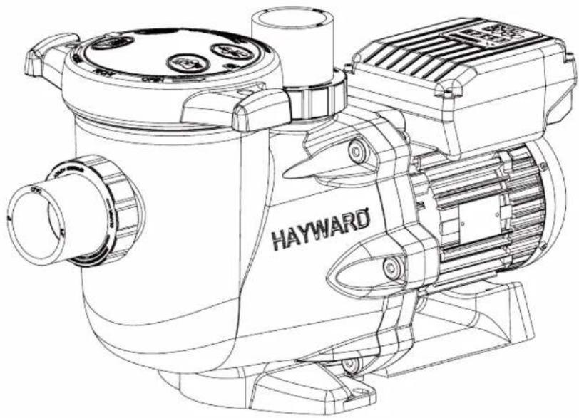
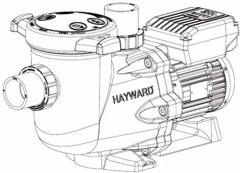
Congratulations, you have just acquired a Hayward® variable speed pump.
Hayward® variable speed pumps® have a state-of-the-art permanent-magnet motor with AC electronic switching. This motor is controlled by a microprocessor combined with a frequency variator providing the following characteristics:
- Rotation speed is displayed on the control display
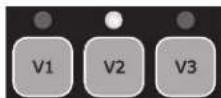
• 3 factory preset rotation speeds (buttons V1, V2, V3), as well as custom speeds set by the user - Regular priming each time you switch on, with adjustable speed and duration
- Skimmer function, which skims the water's surface
• Programmable Timer function
• Current power usage displayed
• Partial and total power consumption displayed - Running time of the pump displayed
- Low noise level
• Construction standard TEFC IP55
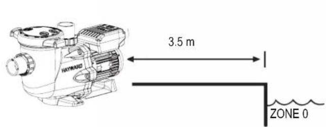
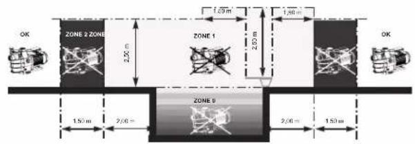
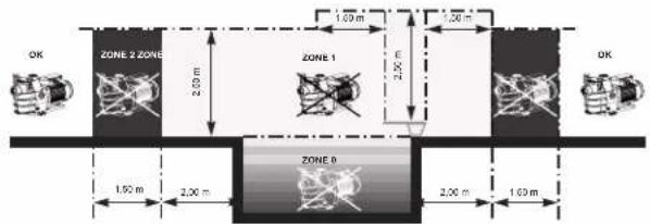
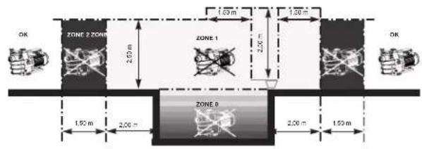
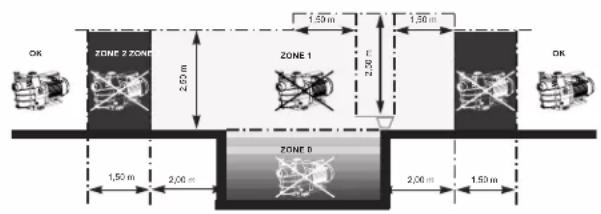
Install the pump at a suitable distance from the pool to reduce the distance between the suction point and the pump as much as possible to avoid pointless excessive pressure drops on the hydraulic circuit.
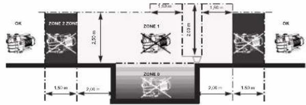
However, it is essential to comply with the safety distance required by the current installation standard (3.5 m minimum). Install and use the product at an altitude less than 2000 m
Install the pump in a dry, well-ventilated place. The motor requires the air to circulate freely around it to allow natural ventilation. Clear a space of at least 0.5m around the pump. Check regularly that no objects, leaves or other debris are blocking the motor cooling system.
The pump must be installed to ensure that the external disconnection switch incorporated into the fixed unit is visible and easily accessible. The switch must be located near to the pump.
The pump must be permanently installed on a concrete base using 8mm lag screws suitable for concrete, screwed into drilled implantation holes. Lock washers must be used to prevent the installation lag screws working loose over time. If the pump has to be mounted on a wooden board, ∅ 8 mm hexagonal wood screws must be used combined with lock washers to prevent the screws working loose over time.
Install the pump under shelter to avoid the control unit being subject to heavy splashing.
The acoustic pressure of Hayward® pumps is less than 70 dBA.
Necessary measures:
- Connect the pump to the earth: Never operate the pump unless it is connected to the earth.
- Connect the pump with a H07RN-F 3G1,5mm ^2 type cable.
- Include a 30 mA differential protection to protect people against electric shocks which may be caused by a breach of the equipment's electrical insulation.
- Include short-circuit protection (the rating is determined according to the value given on the nameplate on the motor).
- Include a means of disconnection from the power supply having an opening distance on the contacts of all the poles ensuring the power supply is completely cut off under the conditions of a category III overvoltage.
⚠ WARNING: Wait 5 minutes after having totally disconnected the pump from the power supply before carrying out any operation on the motor or the connection box: Danger of electric shock which may cause death.
The electric motors fitted to our pumps have thermal protection. This protection reacts in the event of overload or abnormal temperature rise in the motor winding. This protection automatically resets when the winding temperature drops. Whatever the type of motor used, if the regulations require it, a magnetic thermal protection must be installed in addition to the measures described above, which must be calibrated according to the information on the motor's nameplate. The table on page 169 gives the various characteristics of the motors fitted to our pumps.
USE ONLY HAYWARD
® GENUINE REPLACEMENT PARTS
Electrical connection: Ensure that the supply voltage required by the motor corresponds to that of the distribution network and that the section and length of the power cable are adapted to the power and current of the pump.
All the electrical connections on the pump and any change of power cable must be done by a qualified professional to avoid any danger.
When carrying out the electrical connections, comply with the identification under the connection terminals.
Check that the electrical connections are correctly tightened and watertight before switching on the power.
Ensure the cable runs correctly through the opening and ferrite provided for this purpose. The cable gland ensures watertightness around the cable, and the ferrite acts as a filter against electromagnetic disturbance.
Any pre-wiring on our pumps must be removed when the pump is permanently connected to the power supply. This preparation is only used for testing at the factory during the manufacturing phases.
INSTALLATION
Install the pool pump so as to reduce pressure drops to a minimum whilst complying with the distances specified in the installation standard, namely 3.5m minimum between the pump and the pool. The suction pipe must be installed with a slight uphill incline towards the pump axis. Ensure that the connections are correctly tightened and watertight. However, avoid excessively tightening the pipes. For plastic materials, use Teflon only to ensure watertightness. The diameter of the suction pipe shall depend on that of the discharge pipe. Avoid damp or non-ventilated locations. The motor requires the cooling air to circulate freely. Install the pump under shelter to avoid the control unit being subject to heavy splashing.
INSTRUCTIONS FOR START-UP AND PRIMING: Fill the body of the strainer with water up to the level of the suction pipe. Never run the pump without water, as the water is necessary for cooling and lubrication of the mechanical shutter. Open all the suction and discharge pipe valves, and the filter air purge valve if there is one. (Any air in the suction pipes must be eliminated). Start up the generator and wait a reasonable time for priming. Five minutes is not excessive for priming (this time depends on the suction head and the length of the suction pipe). If the pump does not start or does not prime, please refer to the troubleshooting guide.
USING THE CONTROL PANEL
1. INTRODUCTION
Hayward®'s variable speed pump is operated through a control panel that visually displays the operating settings and allows you to adjust them as well as program the Timer mode.
| 1 Power on LED |
| 2 LCD display screen |
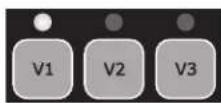
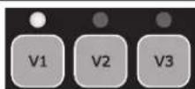
| 3 Choosing the speed |
| 4 Switching between Manual/Timer modes |
| 5 Up/down buttons |
| 6 Start/Stop button |
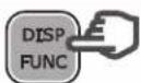
| 7 Display settings button |
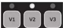
| 8 Selected speed LEDs |

The pump is delivered with DEFAULT SETTINGS(factory settings):
| Priming time (seconds) | Priming speed (rpm) | V1 (rpm) | V2 (rpm) | V3 (rpm) | Skimmer time (minutes) | Skimmer cycle (hours) | Skimmer speed (rpm) |
| 240 3000 | 1500 2400 3000 | 0 15 1hr 2800 |
rpm: Rotations per minute
USE ONLY HAYWARD
® GENUINE REPLACEMENT PARTS
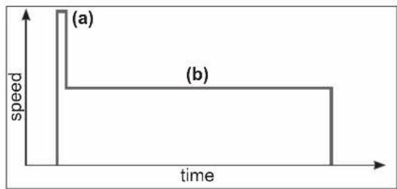
In manual mode, the user can switch the pump on or off manually, according to when the pool is being used.
- When you switch the pump on, it launches a priming phase (a). You can adjust this phase (speed and duration, section 4.2). Priming may be interrupted during start up (section 3.2) or deactivated in the settings.
- The pump speed then stabilizes to a constant rate (b) (stabilization to V2 by default). The user can choose and adjust the speed (section 3.3).
• After switching off and then restarting, the pump will stabilize at the last recorded rate.
line
| time | speed | | ---- | ----- | | 0 | 1 | | Peak | 1 | | Mid | 1 | | End | 0 |2.2 Skimmer
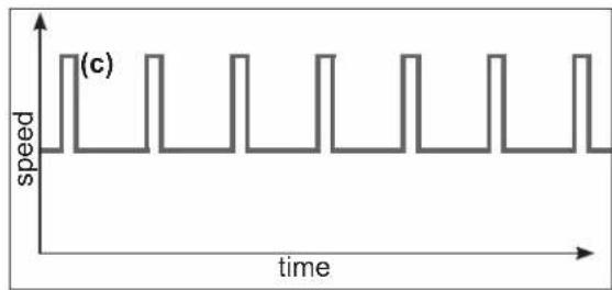
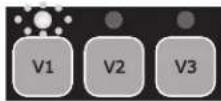
The Skimmer function allows the pump to skim just the water's surface, which is especially useful for preventing dirt from accumulating and stagnating at the surface of the pool.
- The function is automatic: the pump will run at a higher speed (c) for a while and according to a set cycle - both of which you can adjust.
• After running at a higher speed, the pump will adjust to its normal rate - this is the case in both the Manual and Timer modes. - You can deactivate the Skimmer function (see settings in section 4.3).
line
| time | speed | | ---- | ----- | | 0 | 1 | | 1 | 1 | | 2 | 1 | | 3 | 1 | | 4 | 1 | | 5 | 1 | | 6 | 1 | | 7 | 1 | | 8 | 1 | | 9 | 1 | | 10 | 1 | | 11 | 1 | | 12 | 1 | | 13 | 1 | | 14 | 1 | | 15 | 1 | | 16 | 1 | | 17 | 1 | | 18 | 1 | | 19 | 1 | | 20 | 1 | | 21 | 1 | | 22 | 1 | | 23 | 1 | | 24 | 1 | | 25 | 1 | | 26 | 1 | | 27 | 1 | | 28 | 1 | | 29 | 1 | | 30 | 1 | | 31 | 1 | | 32 | 1 | | 33 | 1 | | 34 | 1 | | 35 | 1 | | 36 | 1 | | 37 | 1 | | 38 | 1 | | 39 | 1 | | 40 | 1 | | 41 | 1 | | 42 | 1 | | 43 | 1 | | 44 | 1 | | 45 | 1 | | 46 | 1 | | 47 | 1 | | 48 | 1 | | 49 | 1 | | 50 | 1 | | 51 | 1 | | 52 | 1 | | 53 | 1 | | 54 | 1 | | 55 | 1 | | 56 | 1 | | 57 | 1 | | 58 | 1 | | 59 | 1 | | 60 | 1 | | 61 | 1 | | 62 | 1 | | 63 | 1 | | 64 | 1 | | 65 | 1 | | 66 | 1 | | 67 | 1 | | 68 | 1 | | 69 | 1 | | 70 | 1 | | 71 | 1 | | 72 | 1 | | 73 | 1 | | 74 | 1 | | 75 | 1 | | 76 | 1 | | 77 | 1 | | 78 | 1 | | 79 | 1 | | 80 | 1 | | 81 | 1 | | 82 | 1 | | 83 | 1 | | 84 | 1 | | 85 | 1 | | 86 | 1 | | 87 | 1 | | 88 | 1 | | 89 | 1 | | 90 | 1 | | 91 | 1 | | 92 | 1 | | 93 | 1 | | 94 | 1 | | 95 | 1 | | 96 | 1 | | 97 | 1 | | 98 | 1 | | 99 | 1 | | Note: The actual values in the 'speed' column are not provided in the code. The 'time' label is implied based on the data provided in the code. There is only one data series labeled '(c)' in the chart.2.3 Timer mode
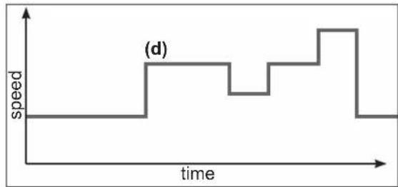
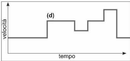
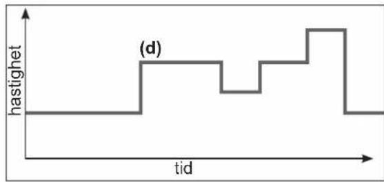
When using the Timer mode, the pump is run automatically 24/7. The user can program (d) the different speed presets. They are selected depending on the installation (heating mode, energy-saving mode etc.) and according to the times the pool is used.
- If the Skimmer function is activated, its sequence will superimpose on the timer one.
- You can stop the pump (pause it) in the Timer mode. When you start it up again, it will run at the speed of the current 'Timer' mode.
- For information on how to program the Timer mode, see section 4.5.
line
| time | speed | | ---- | ----- | | 0 | 0 | | 1 | 0 | | 2 | 0 | | 3 | 0 | | 4 | 0 | | 5 | 0 | | 6 | 0 | | 7 | 0 | | 8 | 0 | | 9 | 0 | | 10 | 0 | | 11 | 0 | | 12 | 0 | | 13 | 0 | | 14 | 0 | | 15 | 0 | | 16 | 0 | | 17 | 0 | | 18 | 0 | | 19 | 0 | | 20 | 0 | | 21 | 0 | | 22 | 0 | | 23 | 0 | | 24 | 0 | | 25 | 0 | | 26 | 0 | | 27 | 0 | | 28 | 0 | | 29 | 0 | | 30 | 0 | | 31 | 0 | | 32 | 0 | | 33 | 0 | | 34 | 0 | | 35 | 0 | | 36 | 0 | | 37 | 0 | | 38 | 0 | | 39 | 0 | | 40 | 0 | | 41 | 0 | | 42 | 0 | | 43 | 0 | | 44 | 0 | | 45 | 0 | | 46 | 0 | | 47 | 0 | | 48 | 0 | | 49 | 0 | | 50 | 0 | | 51 | 0 | | 52 | 0 | | 53 | 0 | | 54 | 0 | | 55 | 0 | | 56 | 0 | | 57 | 0 | | 58 | 0 | | 59 | 0 | | 60 | 0 | | 61 | 0 | | 62 | 0 | | 63 | 0 | | 64 | 0 | | 65 | 0 | | 66 | 0 | | 67 | 0 | | 68 | 0 | | 69 | 0 | | 70 | 0 | | 71 | 0 | | 72 | 0 | | 73 | 0 | | 74 | 0 | | 75 | 0 | | 76 | 0 | | 77 | 0 | | 78 | 0 | | 79 | 0 | | 80 | 0 | | 81 | 0 | | 82 | 0 | | 83 | 0 | | 84 | 0 | | 85 | 0 | | 86 | 0 | | 87 | 0 | | 88 | 0 | | 89 | 0 | | 90 | 0 | | 91 | 0 | | 92 | 0 | | 93 | 0 | | 94 | 0 | | 95 | 0 | | 96 | 0 | | 97 | 0 | | 98 | 0 | | 99 | 0 | |100 | (d) |2.4 Switching between Manual and Timer modes
You can switch between modes by pressing the button
MASE shown below:
Manual mode Timer mode
Displayed speed without prefix
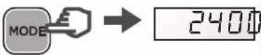
The illuminated LED indicates the selected speed (V2 by default)
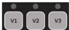
Displayed speed with prefix 't'

The LEDs are switched off
USE ONLY HAYWARD
® GENUINE REPLACEMENT PARTS
2.5 Connecting external digital inputs
⚠️ CAUTION: Before carrying out any electrical work on the pump, unplug the power cord and wait 5 min.
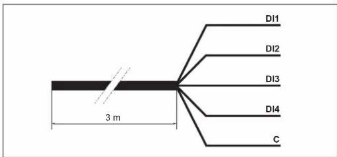
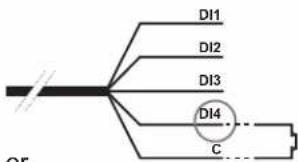
The filtration pump is equipped with a 3-m long 5-wire cord for connecting the 4 digital inputs or potential-free dry contacts (Open/Closed).
Examples of digital inputs
- Assign the speed and flow required for the peripheral devices, such as a heat pump, roller blind or robotic vacuum, etc. to work properly.
• Install a user interface control unit. These digital inputs are used to control, from a distance of 3 m, the Run/Stop function as well as the 3 speeds (V1-V2-V3).
| Assigning the wires | ||
| DI1 Brown Speed | V1 | |
| DI2 Green Speed | V2 | |
| DI3 White Speed | V3 | |
| DI4 Red Run/Stop | ||
| C Black Common | ||
N.B.
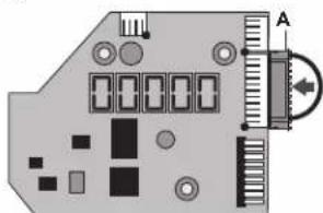
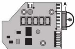
- If the digital inputs are partially used, electrically insulate the unused wires.
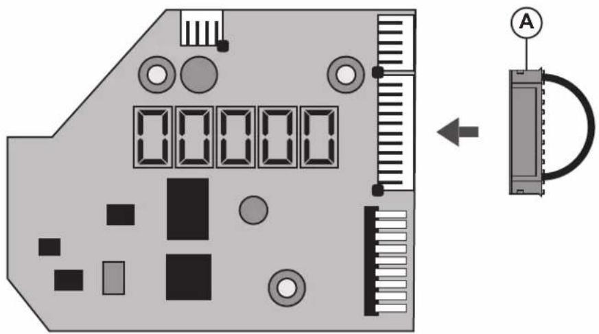
- If the digital inputs are unused, insert the connector (A) instead of the 5-wire cord (see figure below).
USE ONLY HAYWARD
® GENUINE REPLACEMENT PARTS
Operation with the digital inputs
| The digital inputs can be operated in Manual or Timer mode.They have the highest priority level: they act as MASTER over all the functions currently in use.Only the Run/Stop and DISP/FUNC buttons remain active. |  |  |
 |  | |
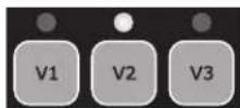
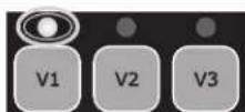
| When a digital input is used, the LED associated with the speed in question blinks rapidly (DI1 = V1, DI2 = V2 or DI3 = V3). |  | 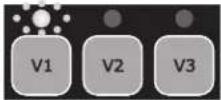 |
| To obtain an action through the digital inputs, the DI4 input must be closed. |  DI4 Run/StopClosed DI4 Run/StopClosed | |||
| If several digital inputs are switched simultaneously, only one will be carried out in the order of priority specified in the table opposite. | DI1 = V1 DI2 = V2 DI3 = V3 | |||
| DI1 = V1 V1 | V2 V3 | |||
| DI2 = V2 V2 | V2 V3 | |||
| DI3 = V3 V3 | V2 V3 | |||
N.B. Once the action associated with the digital input is complete (open contact), the filtration pump resumes the action for the current operational mode.
If the DI4 digital inlet is open, the filtration pump will not start and dSTOP will be displayed on the pump's screen.
- Close the DI4 inlet.
- If necessary press RUN/STOP to start the filtration pump.


natural_image
Pure electrical circuit lines without any symbols
USE ONLY HAYWARD
® GENUINE REPLACEMENT PARTS
'Power' lights up and an LCD test runs on screen, then the software version is displayed on screen


3.2 Priming phase
After switching on the pump, the priming phase starts automatically (this is the same after restarting the pump).
Priming phase begins automatically:
- The speed will climb to 3000 rpm and will last 240 seconds (default settings)


End of priming phase:
- The pump will stabilize at V2 by default or at the last recorded speed.
• The corresponding LED lights up (Manual mode)


To display the remaining time of the priming phase:
- Press DISP/FUNC
- The remaining time is displayed in seconds


To stop the priming phase before it finishes:
- Press RUN/STOP
- The speed will stabilize by default at V2 or at the last recorded speed


3.3 In Manual mode: selecting, setting and saving a custom speed
To select a speed:
- Press one of the speed preset buttons
• The default value will be displayed (in rpm)
• The corresponding LED will light up
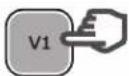


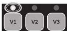
To set a new speed:
- Press the up / down buttons
• The LED will blink: setting speed
- Choose the speed you want (between 600 and 3000 rpm)


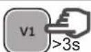
To save the new speed:
- Press and hold the speed preset button for 3 s
- The LED will show a constant light once the speed has been saved


Note: The water flow generated by the pump speed must be adapted to the volume capacity of the installed parts (filter, pipes...). If you are unsure call a professional.
3.4 Stopping / restarting the pump
To stop the pump:
- Press RUN/STOP
- The pump will stop and the speed preset LED will remain illuminated
• In Manual mode the screen will display 'StoP' In Timer mode the screen will flash 'StoP'


To restart the pump:
- Press RUN/STOP
• The pump will begin its priming phase (section 3.2)
• Speed stabilization:
in Manual mode this will be the last recorded speed in Timer mode this will be the operating speed of the Timer preset


USE ONLY HAYWARD
® GENUINE REPLACEMENT PARTS
4. SETTINGS
Note: To adjust the settings the pump must be powered on and in Manual mode (section 2.4), switched off or running (post priming phase).
If no button is pressed for 2 minutes, the display will go back to normal (showing the speed or StoP) and the settings will not be saved.
4.1 Setting the clock
| • Press and hold DISP/FUNC for 3 secondsAll three LEDs will blink• The screen will display "ConF" and then "hr" | 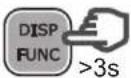 | 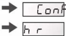 | 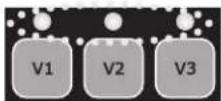 |
| • Press DISP/FUNC to show the time on the internal clock (hh-min) | 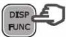 |  | |
| • Press the up / down buttons to adjust the hours / minutes |  | 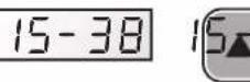 | |
| • Press RUN/STOP to exit and saveThe display will show the current speed or StoP |  |  |  |
| Note: Adjusting the time on the internal clock is important in Timer mode.It will remain saved if the pump is switched off. | |||
Note: Adjusting the time on the internal clock is important in Timer mode. It will remain saved if the pump is switched off.
4.2 Setting the priming phase
| • Press and hold DISP/FUNC for 3 secondsAll 3 LEDs will blink and the screen will display "ConF" | 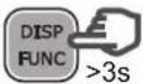 |  | 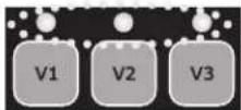 |
| • Press DISP/FUNC repeatedly until 'Pr 240' is displayed on screen - the default priming time (seconds) |  |  | |
| • Press the up / down buttons to set the desired value (0 to 300 seconds) |  |  | |
| • Press DISP/FUNC: the screen will display "o3000" as default priming speed (rpm) | 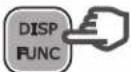 |  | |
| • Press the up / down buttons to display the desired value (max. 3000 rpm) |  |  | |
| • Press RUN/STOP to exit and saveThe display will show the current speed or StoP |  |  | [5toP] |
| Note: If the priming time is set to zero the screen will display "ProFF": priming has been deactivated |  |  | 0 |
USE ONLY HAYWARD
® GENUINE REPLACEMENT PARTS
4.3 Setting the Skimmer function
See section 2.2 for an introduction to this function
| • Press and hold DISP/FUNC for three secondsAll three LEDs will blink and the screen will display"ConF" | 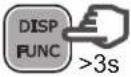 | → |  | 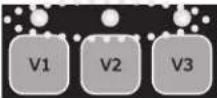 |
| • Press DISP/FUNC repeatedly until 'SFO.15' isdisplayed on screen: this is the default Skimmertime (in minutes) |  | → | 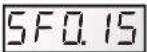 | |
| • Press the up / down buttons to set the desiredvalue (0 to 30 minutes) |  | → |  | |
| • Press DISP/FUNC: the screen will display "St 1hr"- this is the default Skimmer cycle period |  | → |  | |
| • Press the up / down buttons to set the Skimmercycle period to 1hr, 2hrs or 3hrs |  | → |  | |
| • Press DISP/FUNC: the screen will display "S2800"- this is the default speed of the Skimmer function(rpm) |  | → | 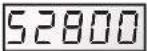 | |
| • Press the up/down buttons to display the desiredspeed (600 to 3000 rpm) |  | → |  | |
| • Press RUN/STOP to exit and saveThe display will show the current speed or StoP |  | → |  | 5toP |
| Note: To deactivate the Skimmer and set the time tozero - display reads "SFoFF" |  | → |  | 51  |
Note: To deactivate the Skimmer and set the time to zero - display reads "SFoFF"
4.4 Restoring the settings
To restore the default settings and erase the Timer mode settings, do the following:
| • Press and hold DISP/FUNC for three secondsAll three LEDs will blink and the screen will display "ConF" | 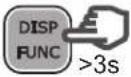 | → |  | 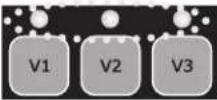 |
| • Press DISP/FUNC repeatedly until the screen displays the message 'Init' | 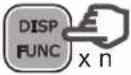 | → | 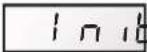 | |
| • Press and hold the 'up' button for 3 seconds. The screen will read "donE" once the reset is complete | 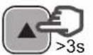 | → |  |  |
Reminder: default settings and their value ranges
| Priming Speed | preset buttons Skimmer function | Timer function | |||||||||||
| Pr | o | V1 | V2 | v3 | 5F | 5t | 5_ | t0 | t1 | t5 | |||
| Units | s | rpm | rpm | rpm | rpm | rpm | min | h | rpm | hh-min | rpm | hh-min | rpm |
| Default | 240 | 3000 | 1500 | 2400 | 3000 | 15 | 1 | 2800 | 06-00 | 2400 | oFF | 0 | |
| Mini | 0 (oFF) | 600 | 600 | 600 | 600 | 0 (oFF) | 1 ... | 600 | 00-00 | — | 00-00 | 0/ 600 | |
| Maxi | 300 | 3000 | 3000 | 3000 | 3000 | 30 | ... 3 | 3000 | 24-00 | — | 24-00 | 3000 | |
USE ONLY HAYWARD
® GENUINE REPLACEMENT PARTS
4.5 Setting the Timer mode
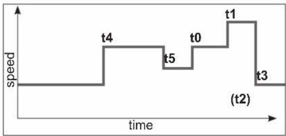
The control panel allows you to program multiple sequences (see section 2.3) or Timers t0 to t5, which do not need to follow a chronological order.
Unused Timer settings will be deactivated.
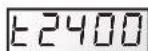
Timer 't0' can be set to 00:00, 06:00 (by default), 12:00 or 18:00. It cannot be deactivated.
You cannot adjust the speed of t0, it is set at 2400 rpm
- Identify the speed profile you would like to program.
The image opposite is shown as an example. - Check whether the internal clock has been set correctly.
line
| Time Point | Speed | | :--- | :--- | | t0 | 1.0 | | t1 | 1.0 | | t2 | 0.5 | | t3 | 0.5 | | t4 | 1.0 | | t5 | 1.0 | The label '(t2)' appears in the bottom right corner, likely indicating a specific event or phase.| • Press and hold DISP/FUNC for 3 secondsAll 3 LEDs will blink and the screen will display"ConF" | 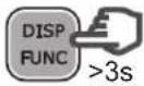 |  | 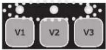 |
| • Press DISP/FUNC twice and the screen willdisplay "t0" | 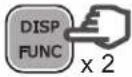 |  | |
| • Press DISP/FUNC: the screen will display "06-00"-this is the default value of t0 |  |  | |
| • Press the up / down buttons to set the value youwould like for t0 (00-00, 06-00, 12-00 or 18-00) |  |  | |
| • Press DISP/FUNC: the screen will display "t1oFF" |  |  | |
| • To activate this Timer setting (as an example),press the 'up' button. The screen will display "t1on" |  |  | |
| • Press DISP/FUNC: the screen will display "00-00" |  |  | |
| • Press the up / down buttons to set the desiredtimetable (hh-mm) |  |  | → |
| • Press DISP/FUNC: the screen will display "0" |  |  | |
| • Press the up / down buttons to display the desiredspeed (600 to 3000 rpm or 0) |  |  | |
| • To go to the next Timer setting, press DISP/FUNC:the screen will display "t2off". In this example theTimer setting stays deactivated |  |  | |
| • Press DISP/FUNC to go to the next Timer settingand repeat the steps (activation, timetable, Timersetting and speed) |  |  | etc ... |
| • Press RUN/STOP to exit and saveThe display will show the current speed or StoP |  |  |
USE ONLY HAYWARD
® GENUINE REPLACEMENT PARTS
5. DISPLAYING CURRENT SETTINGS
Note: The pump must be switched on, either running (post priming phase) or stopped.
To display the current settings, press DISP/FUNC.
If no button is pressed for 15 seconds thereafter, the display will go back to normal (showing the current speed or Stop).
| • Press DISP/FUNC: the screen will display "hr"Press again: the screen will display the internal clock time |  |  | 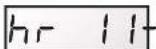 |  |  |  |
| • Press DISP/FUNC: the screen will display "t0"Press again: the screen will display the 0t timetable (the t0 speed is fixed at 2400 rpm) |  |  | 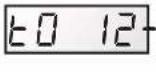 |  |  |  |
| • Press DISP/FUNC: the screen will display "t1"Press again: the screen will display its timetable (hh-mm) |  |  | [6A8Z] |  |  |  |
| • Press DISP/FUNC: the screen will display the speed of the Timer setting (in rpm) | [2HKC] |  |  | |||
| • Press DISP/FUNC: the screen will display the next Timer setting, the timetable and the speed - you can do this up to Timer setting 't5'Note: Deactivated Timer settings are not displayed |  |  |  | etc ... | ||
| • Press DISP/FUNC: the screen will display "P- - - - "Power consumption (in Watts, a value of +/- 10%)Note: P = 0 W when the pump is off. |  |  |  | /ZK4D] | ### | |
| • Press DISP/FUNC: the screen will display "h - - - - "The pump's operating hours counterNote: The counter runs up to 9999 hours |  | ### | ### | |||
| • Press DISP/FUNC: the screen will display "----"Total energy consumption (in kWh)Note: The counter runs up to 99999 kWh |  | ### | ### | |||
| • Press DISP/FUNC: the screen will display "----"Partial energy consumption (in kWh) since the last reset |  | ### | ### | |||
| • To reset the partial energy consumption counter:Press and hold either of the up / down buttons for 3 seconds.The message "CLEAR" will be displayed, indicating that the counter has been reset to zero. |  |  | ### | |||
| • Press DISP/FUNC: The screen will display "SF On" or "SFOFF" to indicate that the Skimmer is on or off |  |  |  | /ZWK4] | ||
| • Press DISP/FUNC: Screen displays "t - - "This is the temperature of the power module (in °C) | [CWZZ] |  |  | |||
| • Press DISP/FUNC to exit back to the normal screen (showing current speed or Stop) |  | ### |  |  | ### |
USE ONLY HAYWARD
® GENUINE REPLACEMENT PARTS
MAINTENANCE
- Completely disconnect the pump from the mains power supply before opening the cover and cleaning the strainer. Clean the strainer basket regularly. Do not bang on the basket to clean it. Check the seal on the cover of the strainer and replace it if necessary.
- The motor shaft is mounted on self-lubricating bearings which do not require any subsequent lubrication.
- Keep the motor clean and dry and ensure the ventilation openings are not blocked.
- The mechanical seal occasionally starts to leak and must then be changed.
- Apart from cleaning the pool, all repairs, servicing and maintenance must be carried out by a Hayward®-approved agent or a qualified person.
Wear parts of the pump mentioned below should be maintained according to their estimated life:
Wear parts estimated life
Mechanical seal 2 years or 10.000 hours.
Motor bearings kit 2 years or 10.000 hours.
Set of gasket (strainer, housing, bulkheads, drain) 2 years or 25.000 hours.
Capacitor
2 years or 10.000
WINTERING
-
Empty the pump by removing all the drain plugs and store them in the strainer basket.
-
Disconnect the pump, remove the pipe connectors and store the entire unit in a dry, well-ventilated place or at least take the following precaution: disconnect the pump, remove the 4 bolts attaching the pump housing to the motor bracket and store the unit in a dry, well-ventilated place. Then cover the pump housing and strainer to protect them.
N.B.: Before recommissioning the pump, clean all the internal parts to remove dust, lime scale etc.
TROUBLESHOOTING
A) The motor does not start
- Check the electrical connections, switches or relays, and the circuit breaker or fuses.
- Ensure that the motor turns freely by hand.
- Check that rotation speeds V1, V2 and V3 are not programmed at 0rpm. If they are, restore the factory settings (see section 4.4).
- If the screen displays any of the error messages below, please contact your vendor:

Constant low line voltage

Constant high line voltage

Power module overheating

Motor overheating

Overload

Internal problem with electrical supply

Starting problems

Internal short-circuiting problem

Multiple problems

Communication problem

Refer to page 21
B) The motor stops, check
- The cables, connections, relays etc.
- Voltage drop on motor (frequently caused by cables that are too small).
- That there is no seizing or overheating (by reading the absorbed current).
N.B.: The motor on your pump is fitted with a thermal protection which, in the case of overload, will automatically cut the circuit and avoid the motor being damaged. This triggering is caused by abnormal usage conditions which need to be checked and corrected. The motor will restart without any intervention as soon as normal operating conditions are restored.
C) "OLOAD" appears on the display (overload or over-heating problem)
- Check that the motor shaft turns freely
- Check that no debris is preventing the turbine from rotating freely
- Check that the motor is correctly ventilated
- After correcting the problem, press the On/Off button
USE ONLY HAYWARD
® GENUINE REPLACEMENT PARTS
D) The pump does not prime
- Ensure the strainer housing is filled with water, that the cover seal is clean and correctly positioned and that no air can enter. If necessary, tighten the cover lock screws.
- Ensure that all the suction and discharge valves are open and not blocked and that the suction outlets in the pool are fully submerged.
- Check that the pump draws by freeing the suction as close as possible to the pump:
a) if the pump does not draw despite being sufficiently full of priming water
- Tighten the bolts and pipe accessories on the suction side.
- Check the voltage to ensure that the pump is rotating at the correct speed.
- Open the pump and check that nothing is blocking it inside,
- Set a priming speed that is fast enough
- Clean the filter and try again
- Replace the mechanical shutter.
b) Try priming in re-circulation mode. If the pump is drawing normally, check the suction pipe and strainer which may be blocked or be allowing air to enter.
- That no air is entering the suction side and causing dull crackling in the pump.
- That there is no cavitation caused by insufficient diameter or a restriction in the suction tube. An over-sized discharge pipe can also cause cavitation. Use pipes of the correct size or purge the pipes if necessary.
- That no vibration is occurring due to incorrect fitting.
- That there are no foreign bodies in the pump housing.
- That the motor bearings have not seized due to excessive clearance, rust or prolonged overheating.
USE ONLY HAYWARD
® GENUINE REPLACEMENT PARTS

natural_image
Abstract geometric logo with stylized letter H inside a circular frame (no text or symbols)HAYWARD®
natural_image
Technical line drawing of a Hayward industrial pump assembly (no text or symbols on the diagram itself)CE UK CA EAC i open book
BOMBA CENTRÍFUGA DE VELOCIDAD VARIABLE
MANUAL DEL USUARIO
CONSERVE ESTE MANUAL PARA CONSULTARLO POSTERIORMENTE

HAYWARD®


line
| Time | Velocity | | :--- | :--- | | 0 | 1 | | 1 | 1 | | 2 | 1 | | 3 | 1 | | 4 | 1 | | 5 | 0 | | 6 | 0 | (a) (approx. 100% of x-axis) (b) (approx. 100% of x-axis) (a) (approx. 100% of x-axis) (b) (approx. 100% of x-axis) (a) (approx. 100% of x-axis) (b) (approx. 100% of x-axis) (a) (approx. 100% of x-axis) (b) (approx. 100% of x-axis) (a) (approx. 100% on x-axis) (b) (approx. 100% on x-axis)2.2 Skimmer
line
| tiempo | velocidad | | ------ | --------- | | 0 | 0 | | 1 | 0 | | 2 | 0 | | 3 | 0 | | 4 | 0 | | 5 | 0 | | 6 | 0 | | 7 | 0 | | 8 | 0 | | 9 | 0 | | 10 | 0 | | 11 | 0 | | 12 | 0 | | 13 | 0 | | 14 | 0 | | 15 | 0 | | 16 | 0 | | 17 | 0 | | 18 | 0 | | 19 | 0 | | 20 | 0 | | 21 | 0 | | 22 | 0 | | 23 | 0 | | 24 | 0 | | 25 | 0 | | 26 | 0 | | 27 | 0 | | 28 | 0 | | 29 | 0 | | 30 | 0 | | 31 | 0 | | 32 | 0 | | 33 | 0 | | 34 | 0 | | 35 | 0 | | 36 | 0 | | 37 | 0 | | 38 | 0 | | 39 | 0 | | 40 | 0 | | 41 | 0 | | 42 | 0 | | 43 | 0 | | 44 | 0 | | 45 | 0 | | 46 | 0 | | 47 | 0 | | 48 | 0 | | 49 | 0 | | 50 | 0 | | 51 | 0 | | 52 | 0 | | 53 | 0 | | 54 | 0 | | 55 | 0 | | 56 | 0 | | 57 | 0 | | 58 | 0 | | 59 | 0 | | 60 | 0 | | 61 | 0 | | 62 | 0 | | 63 | 0 | | 64 | 0 | | 65 | 0 | | 66 | 0 | | 67 | 0 | | 68 | 0 | | 69 | 0 | | 70 | 0 | | 71 | 0 | | 72 | 0 | | 73 | 0 | | 74 | 0 | | 75 | 0 | | 76 | 0 | | 77 | 0 | | 78 | 0 | | 79 | 0 | | 80 | 0 | | 81 | 0 | | 82 | 0 | | 83 | 0 | | 84 | 0 | | 85 | 0 | | 86 | 0 | | 87 | 0 | | 88 | 0 | | 89 | 0 | | 90 | 0 | | 91 | 0 | | 92 | 0 | | 93 | 0 | | 94 | 0 | | 95 | 0 | | 96 | 0 | | 97 | 0 | | 98 | 0 | | 99 | 0 | |1 | |USE SOLO PIEZAS DE REPUESTO ORIGINALES DE HAYWARD
®


USE SOLO PIEZAS DE REPUESTO ORIGINALES DE HAYWARD
®
3. USO
3.1 Conexión
natural_image
Abstract geometric logo with stylized letter H inside a dark circular frame (no text or symbols)HAYWARD®

natural_image
Technical line drawing of a Hayward industrial pump or motor assembly (no text or symbols on the diagram itself)
BOMBA CENTRÍFUGA DE VELOCIDADE VARIÁVEL
MANUAL DO UTILIZADOR
CONSERVE ESTE MANUAL PARA REFERÊNCIA FUTURA

HAYWARD®


line
| tempo | velocidade | | ----- | ---------- | | 0 | 0 | | 1 | 0 | | 2 | 0 | | 3 | 0 | | 4 | 0 | | 5 | 0 | | 6 | 0 | | 7 | 0 | | 8 | 0 | | 9 | 0 | | 10 | 0 | | 11 | 0 | | 12 | 0 | | 13 | 0 | | 14 | 0 | | 15 | 0 | | 16 | 0 | | 17 | 0 | | 18 | 0 | | 19 | 0 | | 20 | 0 | | 21 | 0 | | 22 | 0 | | 23 | 0 | | 24 | 0 | | 25 | 0 | | 26 | 0 | | 27 | 0 | | 28 | 0 | | 29 | 0 | | 30 | 0 | | 31 | 0 | | 32 | 0 | | 33 | 0 | | 34 | 0 | | 35 | 0 | | 36 | 0 | | 37 | 0 | | 38 | 0 | | 39 | 0 | | 40 | 0 | | 41 | 0 | | 42 | 0 | | 43 | 0 | | 44 | 0 | | 45 | 0 | | 46 | 0 | | 47 | 0 | | 48 | 0 | | 49 | 0 | | 50 | 0 | | 51 | 0 | | 52 | 0 | | 53 | 0 | | 54 | 0 | | 55 | 0 | | 56 | 0 | | 57 | 0 | | 58 | 0 | | 59 | 0 | | 60 | 0 | | 61 | 0 | | 62 | 0 | | 63 | 0 | | 64 | 0 | | 65 | 0 | | 66 | 0 | | 67 | 0 | | 68 | 0 | | 69 | 0 | | 70 | 0 | | 71 | 0 | | 72 | 0 | | 73 | 0 | | 74 | 0 | | 75 | 0 | | 76 | 0 | | 77 | 0 | | 78 | 0 | | 79 | 0 | | 80 | 0 | | 81 | 0 | | 82 | 0 | | 83 | 0 | | 84 | 0 | | 85 | 0 | | 86 | 0 | | 87 | 0 | | 88 | 0 | | 89 | 0 | | 90 | 0 | | 91 | 0 | | 92 | 0 | | 93 | 0 | | 94 | 0 | | 95 | 0 | | 96 | 0 | | 97 | 0 | | 98 | 0 | | 99 | 0 | | Note: The actual values for "Velocity" are not provided in the code. The code is a schematic representation of the data being plotted. The actual values are labeled as "(d)".UTILIZE APENAS COMPONENTES DE SUBSTITUIÇÃO GENUÍNOS HAYWARD
®
| DI1 = V1 DI2 = V2 DI3 = V3 |
| DI1 = V1 V1 | V2 V3 |
| DI2 = V2 V2 | V2 V3 |
| DI3 = V3 V3 V2 V3 |
natural_image
Pure electrical circuit lines without any symbols
UTILIZE APENAS COMPONENTES DE SUBSTITUIÇÃO GENUÍNOS HAYWARD
®
3. UTILIZAÇÃO
natural_image
Abstract geometric logo with stylized letter H inside a circular frame (no text or symbols)HAYWARD®
natural_image
Technical line drawing of a Hayward industrial pump or motor assembly (no text or symbols on the diagram itself)
ZENTRIFUGALPUMPE MIT VARIABLER GESCHWINDIGKEIT
ANWENDER - HANDBUCH
VERWENDEN SIE NUR ORIGINAL-ERSATZTEILE VON HAYWARD
®
natural_image
Diagram of a circuit board with components and a ruler, no readable text or symbols present

VERWENDEN SIE NUR ORIGINAL-ERSATZTEILE VON HAYWARD
®
3. BEDIENUNG
natural_image
Abstract geometric logo with stylized letter H inside a circular frame (no text or symbols)HAYWARD®

natural_image
Technical line drawing of a Hayward industrial pump or motor assembly (no text or symbols on the diagram itself)
CENTRIFUGAALPOMP MET VARIABELE SNELHEID
GEBRUIKERSHANDBOEK
DIT HANDBOEK BEWAREN VOOR TOEKOMSTIG GEBRUIK

HAYWARD®

line
| tijd | snelheid | | ---- | -------- | | 0 | 0 | | 1 | 0 | | 2 | 1 | | 3 | 1 | | 4 | 0 | | 5 | 1 | | 6 | 1 | | 7 | 1 | | 8 | 1 | | 9 | 1 | | 10 | 1 | | 11 | 0 | | 12 | 0 | | 13 | 0 | | 14 | 0 | | 15 | 0 | | 16 | 0 | | 17 | 0 | | 18 | 0 | | 19 | 0 | | 20 | 0 | | 21 | 0 | | 22 | 0 | | 23 | 0 | | 24 | 0 | | 25 | 0 | | 26 | 0 | | 27 | 0 | | 28 | 0 | | 29 | 0 | | 30 | 0 | | 31 | 0 | | 32 | 0 | | 33 | 0 | | 34 | 0 | | 35 | 0 | | 36 | 0 | | 37 | 0 | | 38 | 0 | | 39 | 0 | | 40 | 0 | | 41 | 0 | | 42 | 0 | | 43 | 0 | | 44 | 0 | | 45 | 0 | | 46 | 0 | | 47 | 0 | | 48 | 0 | | 49 | 0 | | 50 | 0 | | 51 | 0 | | 52 | 0 | | 53 | 0 | | 54 | 0 | | 55 | 0 | | 56 | 0 | | 57 | 0 | | 58 | 0 | | 59 | 0 | | 60 | 0 | | 61 | 0 | | 62 | 0 | | 63 | 0 | | 64 | 0 | | 65 | 0 | | 66 | 0 | | 67 | 0 | | 68 | 0 | | 69 | 0 | | 70 | 0 | | 71 | 0 | | 72 | 0 | | 73 | 0 | | 74 | 0 | | 75 | 0 | | 76 | 0 | | 77 | 0 | | 78 | 0 | | 79 | 0 | | 80 | 0 | | 81 | 0 | | 82 | 0 | | 83 | 0 | | 84 | 0 | | 85 | 0 | | 86 | 0 | | 87 | 0 | | 88 | 0 | | 89 | 0 | | 90 | 0 | | 91 | 0 | | 92 | 0 | | 93 | 0 | | 94 | 0 | | 95 | 0 | | 96 | 0 | | 97 | 0 | | 98 | 0 | | 99 | 0 | | Note: The data is labeled as "(d)" in the chart. The y-axis label is "snelheid". There is no additional data series in this image. The label above the chart is "d".ENKEL ORIGINELE RESERVEONDERDELEN VAN HAYWARD
® GEBRUIKEN.
natural_image
Diagram of a circuit board with components and a scale indicator (no text or symbols)

ENKEL ORIGINELE RESERVEONDERDELEN VAN HAYWARD
® GEBRUIKEN.
3. GEBRUIK
3.1 Inschakelen
natural_image
Abstract geometric logo with stylized letter H inside a circular frame (no text or symbols)HAYWARD®
natural_image
Technical line drawing of a Hayward industrial pump or motor assembly (no text or symbols on the diagram itself)
POMPA CENTRIFUGA A VELOCITÀ VARIABILE
MANUALE PER L'USO
line
| tempo | velocità | |---|---| | 0 | 1 | | 1 | 1 | | 2 | 1 | | 3 | 0 | (a) (line segment) (b) (line segment) (a) (line segment) (b) (line segment) (a) (line segment) (b) (line segment) (a) (line segment) (b) (line segment) (a) (line segment) (b) (line segment) (a) (line segment) (b) (line segment) (a) (line segment) (b) (line segment) (a) (line segment) (b) (line segment) (a) - (b) (line segment) (a) - (b) (line segment) (b) (line segment) (a) - (b) (line segment) (b) (line segment) (a) - (b) (line segment) (b) - (a) - (b) (line segment) (a) - (b) - (b) (line segment) (a) - (b) - (b) (line segment) (a) - (b) - (b) (line segment) (a) - (b) - (b) (line segment)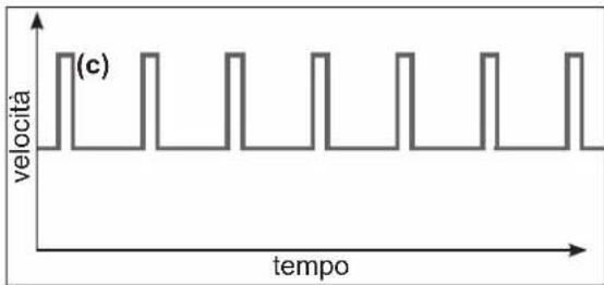
MODE
UTILIZZARE ESCLUSIVAMENTE PARTI DI RICAMBIO ORIGINALI HAYWARD
®
UTILIZZARE ESCLUSIVAMENTE PARTI DI RICAMBIO ORIGINALI HAYWARD
®
natural_image
Abstract geometric logo with stylized letter H inside a circular frame (no text or symbols)HAYWARD®
natural_image
Technical line drawing of a Hayward industrial pump or motor assembly (no text or symbols on the diagram itself)
CENTRIFUGALPUMP MED VARIABELT VARVTAL
ANVÄNDARHANDLEDNING
SPARA DENNA HANDLEDNING FÖR SENARE REFERENS
line
| tid | hastighet | | --- | --------- | | 0 | 1 | | 1 | 0 | | 2 | 0 | | 3 | 0 | | 4 | 0 |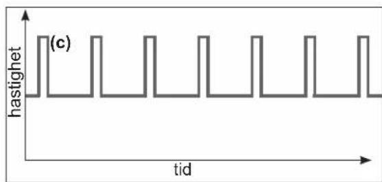
line
| tid | hastighet | | --- | --------- | | 0 | 0 | | 1 | 0 | | 2 | 0 | | 3 | 0 | | 4 | 0 | | 5 | 0 | | 6 | 0 | | 7 | 0 | | 8 | 0 | | 9 | 0 | | 10 | 0 | | 11 | 0 | | 12 | 0 | | 13 | 0 | | 14 | 0 | | 15 | 0 | | 16 | 0 | | 17 | 0 | | 18 | 0 | | 19 | 0 | | 20 | 0 | | 21 | 0 | | 22 | 0 | | 23 | 0 | | 24 | 0 | | 25 | 0 | | 26 | 0 | | 27 | 0 | | 28 | 0 | | 29 | 0 | | 30 | 0 | | 31 | 0 | | 32 | 0 | | 33 | 0 | | 34 | 0 | | 35 | 0 | | 36 | 0 | | 37 | 0 | | 38 | 0 | | 39 | 0 | | 40 | 0 | | 41 | 0 | | 42 | 0 | | 43 | 0 | | 44 | 0 | | 45 | 0 | | 46 | 0 | | 47 | 0 | | 48 | 0 | | 49 | 0 | | 50 | 0 | | 51 | 0 | | 52 | 0 | | 53 | 0 | | 54 | 0 | | 55 | 0 | | 56 | 0 | | 57 | 0 | | 58 | 0 | | 59 | 0 | | 60 | 0 | | 61 | 0 | | 62 | 0 | | 63 | 0 | | 64 | 0 | | 65 | 0 | | 66 | 0 | | 67 | 0 | | 68 | 0 | | 69 | 0 | | 70 | 0 | | 71 | 0 | | 72 | 0 | | 73 | 0 | | 74 | 0 | | 75 | 0 | | 76 | 0 | | 77 | 0 | | 78 | 0 | | 79 | 0 | | 80 | 0 | | Note: The actual values for 'hastighet' are not provided in the code. The code does not provide the exact values from the input 't' to the output 't'.natural_image
Diagram of a computer motherboard with labeled components and a scale indicator (no readable text or symbols)
3. ANVÄNDNING
3.1 Aktiverad
line
| tid | hastighet | | --- | --------- | | t0 | 0 | | t1 | 1 | | t2 | 0 | | t3 | 0 | | t4 | 1 | | t5 | 0 |natural_image
Abstract geometric logo with stylized letter 'H' inside a circular frame (no text or symbols)HAYWARD®

natural_image
Technical line drawing of a Hayward industrial pump or motor assembly (no text or symbols on the diagram itself)
SENTRIFUGALPUMPE MED VARIABEL HASTIGHET
BRUKERVEILEDNING
TA VARE PÅ DENNE VEILEDNINGEN FOR SENERE BRUK
line
| tid | hastighet | |---|---| | 0 | 1 | | 1 | 1 | | 2 | 1 | | 3 | 1 | | 4 | 1 | (a) (top-left) (a) (b) (bottom-right)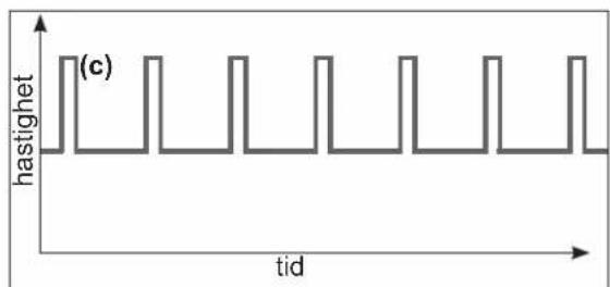
line
| tid | hastighet | | --- | --------- | | 0 | 1 | | 1 | 0 | | 2 | 1 | | 3 | 0 | | 4 | 1 | | 5 | 0 | | 6 | 1 | | 7 | 0 | | 8 | 1 | | 9 | 0 | | 10 | 1 | | 11 | 0 | | 12 | 1 | | 13 | 0 | | 14 | 1 | | 15 | 0 | | 16 | 1 | | 17 | 0 | | 18 | 1 | | 19 | 0 | | 20 | 1 | | 21 | 0 | | 22 | 1 | | 23 | 0 | | 24 | 1 | | 25 | 0 | | 26 | 1 | | 27 | 0 | | 28 | 1 | | 29 | 0 | | 30 | 1 | | 31 | 0 | | 32 | 1 | | 33 | 0 | | 34 | 1 | | 35 | 0 | | 36 | 1 | | 37 | 0 | | 38 | 1 | | 39 | 0 | | 40 | 1 | | 41 | 0 | | 42 | 1 | | 43 | 0 | | 44 | 1 | | 45 | 0 | | 46 | 1 | | 47 | 0 | | 48 | 1 | | 49 | 0 | | 50 | 1 | | 51 | 0 | | 52 | 1 | | 53 | 0 | | 54 | 1 | | 55 | 0 | | 56 | 1 | | 57 | 0 | | 58 | 1 | | 59 | 0 | | 60 | 1 | | Note: The actual values for 'hastighet' are not provided in the code. The code is marked as '(c)' in the top-left corner. The rest of the chart is empty. The text 'tid' appears to be part of the plot area.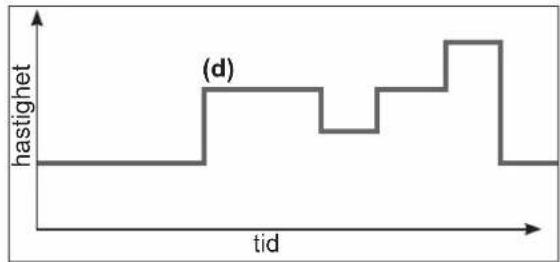
line
| tid | hastighet | | --- | --------- | | 0 | 0 | | 1 | 0 | | 2 | 0 | | 3 | 0 | | 4 | 0 | | 5 | 0 | | 6 | 0 | | 7 | 0 | | 8 | 0 | | 9 | 0 | | 10 | 0 | | 11 | 0 | | 12 | 0 | | 13 | 0 | | 14 | 0 | | 15 | 0 | | 16 | 0 | | 17 | 0 | | 18 | 0 | | 19 | 0 | | 20 | 0 | | 21 | 0 | | 22 | 0 | | 23 | 0 | | 24 | 0 | | 25 | 0 | | 26 | 0 | | 27 | 0 | | 28 | 0 | | 29 | 0 | | 30 | 0 | | 31 | 0 | | 32 | 0 | | 33 | 0 | | 34 | 0 | | 35 | 0 | | 36 | 0 | | 37 | 0 | | 38 | 0 | | 39 | 0 | | 40 | 0 | | 41 | 0 | | 42 | 0 | | 43 | 0 | | 44 | 0 | | 45 | 0 | | 46 | 0 | | 47 | 0 | | 48 | 0 | | 49 | 0 | | 50 | 0 | | 51 | 0 | | 52 | 0 | | 53 | 0 | | 54 | 0 | | 55 | 0 | | 56 | 0 | | 57 | 0 | | 58 | 0 | | 59 | 0 | | 60 | 0 | | 61 | 0 | | 62 | 0 | | 63 | 0 | | 64 | 0 | | 65 | 0 | | 66 | 0 | | 67 | 0 | | 68 | 0 | | 69 | 0 | | 70 | 0 | | 71 | 0 | | 72 | 0 | | 73 | 0 | | 74 | 0 | | 75 | 0 | | 76 | 0 | | 77 | 0 | | 78 | 0 | | 79 | 0 | | 80 | -1 | | | |2.4 Skifte mellom Manuell modus / Timer-modus
BRUK UTELUKKENDE OPPRINNELIGE RESERVEDELER FRA HAYWARD
®
line
| tid | hastighet | | --- | --------- | | t0 | 0 | | t1 | 1 | | t2 | 0 | | t3 | 0 | | t4 | 1 | | t5 | 0 |natural_image
Abstract geometric logo with stylized letter H inside a circular frame (no text or symbols)HAYWARD®

natural_image
Technical line drawing of a Hayward industrial pump assembly (no text or symbols on the diagram itself)
CENTRIFUGEPUMPE MED VARIABEL HASTIGHED
BRUGERVEJLEDNING
OPBEVAR DENNE MANUAL TIL SENERE BRUG

HAYWARD®


ADVARSEL: Elektrisk fare. Manglende overholdelse af instruktionerne kan resultere i alvorlig personskade eller død. TIL BRUG I SV∅MMEBASSER
line
| tid | hastighed | |---|---| | 0 | 1 | | 1 | 1 | | 2 | 1 | | 3 | 1 | | 4 | 0 | (a) (top-left) (b) (bottom-right)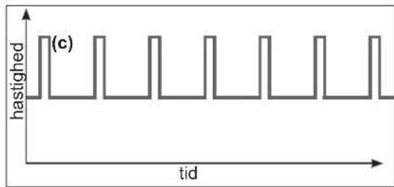
line
| tid | hastighed | | --- | --------- | | 0 | 1 | | 1 | 1 | | 2 | 1 | | 3 | 1 | | 4 | 1 | | 5 | 1 | | 6 | 1 | | 7 | 1 | | 8 | 1 | | 9 | 1 | | 10 | 1 | | 11 | 1 | | 12 | 1 | | 13 | 1 | | 14 | 1 | | 15 | 1 | | 16 | 1 | | 17 | 1 | | 18 | 1 | | 19 | 1 | | 20 | 1 | | 21 | 1 | | 22 | 1 | | 23 | 1 | | 24 | 1 | | 25 | 1 | | 26 | 1 | | 27 | 1 | | 28 | 1 | | 29 | 1 | | 30 | 1 | | 31 | 1 | | 32 | 1 | | 33 | 1 | | 34 | 1 | | 35 | 1 | | 36 | 1 | | 37 | 1 | | 38 | 1 | | 39 | 1 | | 40 | 1 | | 41 | 1 | | 42 | 1 | | 43 | 1 | | 44 | 1 | | 45 | 1 | | 46 | 1 | | 47 | 1 | | 48 | 1 | | 49 | 1 | | 50 | 1 | | 51 | 1 | | 52 | 1 | | 53 | 1 | | 54 | 1 | | 55 | 1 | | 56 | 1 | | 57 | 1 | | 58 | 1 | | 59 | 1 | | 60 | 1 | | | |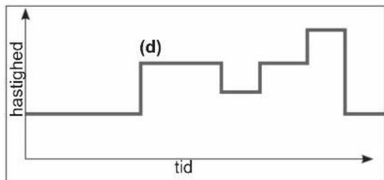
line
| tid | hastighed | | --- | --------- | | 0 | 0 | | 1 | 0 | | 2 | 1 | | 3 | 1 | | 4 | 0 | | 5 | 1 | | 6 | 1 | | 7 | 1 | | 8 | 1 | | 9 | 1 | | 10 | 0 | | 11 | 0 | | 12 | 0 | | 13 | 0 | | 14 | 0 | | 15 | 0 | | 16 | 0 | | 17 | 0 | | 18 | 0 | | 19 | 0 | | 20 | 0 | | 21 | 0 | | 22 | 0 | | 23 | 0 | | 24 | 0 | | 25 | 0 | | 26 | 0 | | 27 | 0 | | 28 | 0 | | 29 | 0 | | 30 | 0 | | 31 | 0 | | 32 | 0 | | 33 | 0 | | 34 | 0 | | 35 | 0 | | 36 | 0 | | 37 | 0 | | 38 | 0 | | 39 | 0 | | 40 | 0 | | 41 | 0 | | 42 | 0 | | 43 | 0 | | 44 | 0 | | 45 | 0 | | 46 | 0 | | 47 | 0 | | 48 | 0 | | 49 | 0 | | 50 | 0 | | 51 | 0 | | 52 | 0 | | 53 | 0 | | 54 | 0 | | 55 | 0 | | 56 | 0 | | 57 | 0 | | 58 | 0 | | 59 | 0 | | 60 | 0 | | 61 | 0 | | 62 | 0 | | 63 | 0 | | 64 | 0 | | 65 | 0 | | 66 | 0 | | 67 | 0 | | 68 | 0 | | 69 | 0 | | 70 | 0 | | 71 | 0 | | 72 | 0 | | 73 | 0 | | 74 | 0 | | 75 | 0 | | 76 | 0 | | 77 | 0 | | 78 | 0 | | 79 | 0 | | 80 | 0 | | Note: The actual values for 'hastighed' are not provided in the code. The code does not provide the exact values from the input 'tid'.BRUG UDELUKKENDE ORIGINALE HAYWARD
® RESERVEDELE
natural_image
Abstract geometric logo with stylized letter H inside a circular frame (no text or symbols)HAYWARD®

natural_image
Technical line drawing of a Hayward industrial pump or motor assembly (no text or symbols on the diagram itself)CE UK CA EAC i open book
KESKIPAKOPUMPPU SÄÄDETTÄVÄLLÄ NOPEUDELLA
KÄYTTÖOHJE
SÄILYTÄ TÄMÄ KÄYTTÖOHJE MYÖHEMPÄÄ TARVETTA VARTEN
line
| aika | pyörimisnopeus | |---|---| | 0 | 1 | | 1 | 1 | | 2 | 1 | | 3 | 0 | (a) (labeled) (b) (labeled) (a) (labeled) (b) (labeled) (a) (labeled) (b) (a)KÄYTÄ AINOASTAAN ALKUPERÄISIÄ HAYWARD
®-VARAOSIA
| DI1 = V1 DI2 = V2 DI3 = V3 |
natural_image
Electronic circuit board with component layout and measurement scale (no readable text or symbols)
KÄYTÄ AINOASTAAN ALKUPERÄISIÄ HAYWARD
®-VARAOSIA
3. KÄYTTÖ
MAHDOLLISET VIAT JA RATKAISUT
natural_image
Abstract geometric logo with stylized letter H inside a circular frame (no text or symbols)HAYWARD®

natural_image
Technical line drawing of a Hayward industrial pump unit (no text or symbols on the diagram itself)
line
| время | скорость | | ------ | --------- | | 0 | 0 | | 1 | 0 | | 2 | 0 | | 3 | 0 | | 4 | 0 | | 5 | 0 | | 6 | 0 | | 7 | 0 | | 8 | 0 | | 9 | 0 | | 10 | 0 | | 11 | 0 | | 12 | 0 | | 13 | 0 | | 14 | 0 | | 15 | 0 | | 16 | 0 | | 17 | 0 | | 18 | 0 | | 19 | 0 | | 20 | 0 | | 21 | 0 | | 22 | 0 | | 23 | 0 | | 24 | 0 | | 25 | 0 | | 26 | 0 | | 27 | 0 | | 28 | 0 | | 29 | 0 | | 30 | 0 | | 31 | 0 | | 32 | 0 | | 33 | 0 | | 34 | 0 | | 35 | 0 | | 36 | 0 | | 37 | 0 | | 38 | 0 | | 39 | 0 | | 40 | 0 | | 41 | 0 | | 42 | 0 | | 43 | 0 | | 44 | 0 | | 45 | 0 | | 46 | 0 | | 47 | 0 | | 48 | 0 | | 49 | 0 | | 50 | 0 | | 51 | 0 | | 52 | 0 | | 53 | 0 | | 54 | 0 | | 55 | 0 | | 56 | 0 | | 57 | 0 | | 58 | 0 | | 59 | 0 | | 60 | 0 | | 61 | 0 | | 62 | 0 | | 63 | 0 | | 64 | 0 | | 65 | 0 | | 66 | 0 | | 67 | 0 | | 68 | 0 | | 69 | 0 | | 70 | 0 | | 71 | 0 | | 72 | 0 | | 73 | 0 | | 74 | 0 | | 75 | 0 | | 76 | 0 | | 77 | 0 | | 78 | 0 | | 79 | 0 | | 80 | 0 | | 81 | 0 | | 82 | 0 | | 83 | 0 | | 84 | 0 | | 85 | 0 | | 86 | 0 | | 87 | 0 | | 88 | 0 | | 89 | 0 | | 90 | 0 | | 91 | 0 | | 92 | 0 | | 93 | 0 | | 94 | 0 | | 95 | 0 | | 96 | 0 | | 97 | 0 | | 98 | 0 | | 99 | 0 | |1 | |natural_image
Pure electrical circuit lines without any symbols

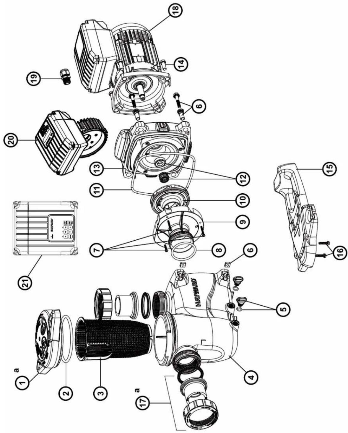
| No | Description · Description · Descripción · Descrição · Bezeichnung · Beschrijving · Descrizione · Beskrivning · Beskrivelse · Beskrivelse · Kuvaus · Описание |
| 1 | Strainer cover · Couvercle de préfiltre · Tapa de prefiltro · Tampa do filtro · Deckel · Zeef dekking · Coperchio prefiltro · Silskydd · Sildeksel · Si dæksel · Siivilä kansi · Крышка префильтра |
| 2 | Strainer cover O-Ring · Joint torique de préfiltre · Junta tórica · Junta tórica da tampa do filtro · O-Ring · De O-ring van de zeefdekking · Guarnizione O'ring · Silskydd O-ring · Sildeksel O-Ring · Sidæksel O-ring · Siivilä kannen O-rengas · Уплотнительное кольцо |
| 3 | Strainer basket · Panier de préfiltre · Cesto filtrante · Cesta do filtro · Filterkorb · Zeef mand · Cestino prefiltro · Silkorg · Sil kurv · Si kurv · Siivilä kori · Корзина пр |
| 4 | Pump Housing/Strainer · Corps de pompe et préfiltre · Cuerpo bomba y prefiltro · Corpo de bomba e préfiltre · Pumpengehäuse/Vorfilter · Lichaam van pomp en préfiltre · Corpo pompa/Prefiltro · Pumphus/sil · Pumpehus/sil · Pumpehus/si · Pumpun kotelo/siivilä · Kopnyc насоса |
| 5 | Drain Plug · Bouchon de vidange · Tapón de vaciado · Plugue de dreno · Ablasschraube · Afvoerkanaal stop · Tappo di spurgo · Avtappningsplugg · Dreneringsplugg · Bundprop · Tyhjennystulppa · Сливная пробка |
| 6 | Housing insert & seal plate spacer kit · Inserts de corps · Partes de cuerpo · Inserts de corpos · KörperEinlagen · Inserts van lichamen · Inserzioni di corpo · Husinsats & tätningsplatta distanssats · Avstandssett for husinnsats og tetningsplate · Husindsats & tætningsplade afstandssæt · Kotelon sisäosa ja tiivistelievyn välikesarja · Втулка |
| 7 | Diffuser gasket · Joint de diffuseur · Junta de difusor · Junta de difusor · Dichtung · Verbindingsstuk van verspreider · Guarnizione diffusore · Diffusor packning · Diffuserpakning · Diffuser pakning · Hajottimen tiiviste · Прокладка |
| 8 | Disffuser screws (x2) · Vis de diffuseur (x2) · Tornillo de difusor (x2) · Tornillos do difusor (x2) · Zerstäuberschraube (x2) · Schroef van verspreider (x2) · Vite di diffusore (x2) · Spridningsskruvar (x2) · Sprederskruer (x2) · Sprederskruer (x2) · Hajottimen ruuvit (x2) · Комплект винтов (x2) |
| 9 | Diffuser · Diffuseur · Difusor · Difusor · Leitapparat · Verspreide · Diffusore · Diffuser · Spreader · Diffuser · Hajotin · Диффузор |
| 10 | Impeller screw · Vis de turbine · Tornillo de turbina · Tornillos de turbina · Turbinenschraube · Schroef van turbine · Vite di turbina · Impellerskruv · Impeller skrue · Løbehjulsskrue · Juoksupyörån ruuvi · Комплект винтов |
| 11 | Ring for impeller · Bague pour turbine · Anillo para turbina · Ring de turbina · Ring für Laufrad · Ring voor Turbine · Anello · Ring för pumphjul · Ring for impeller · Ring til pumpehjul · Rengas juoksupyörälle · Уплотнительное кольцо |
| 12 | Impeller · Turbine · Turbina · Turbina · Laufrad · Turbine · Girante · Impeller · Impeller · Løbehjul · Juoksupyörä · Крыльчатка |
| 13 | Shaft Seal assembly · Obturateur mécanique · Cierre mecánico · Conjunto de selo · Motorhalterung · Verbindings assemblage · Tenuta meccanica · Axeltätningsenhet · Akseltetningsenhet · Akseltætningssamling · Akseltiivisteen kokoonpano · Сальник в сборе |
| 14 | Housing gasket · Joint de corps · Junta · Gaxeta da carcaça · Dichtung · Huisvestings pakking · Guarnizione corpo · Huspackning · Huspakning · Huspakning · Kotelon tiiviste · Прокладка |
| 15 | Seal plate · Plateau d'étanchéité · Plato de cierre · Placa do selo · Flansch · Verbindings plaat · Supporto di fissaggio · Tätningsplatta · Forseglingsplate · Tætningsplade · Tiivistelevy · Фланец |
| 16 | Housing bolt · Vis corps de pompe · Tornillo cabeza exagonal · Tornillos de tampão da carcaça · Sechskantschraube · Huisvestings GLB schroeven · Viti a testa esagonale · Husbult · Husbolt · Husbolt · Kotelon pultti · Комплект болтов |
| 17 | Motor bolt · Vis moteur · Tornillo · Tornillos a motor · Sechskrantschraube · Schroef motor · Viti · Motorbolt · Motorbolt · Motor bolt · Moottorin pultti · Комплект болтов |
| 18 | Motor · Moteur · Motor · Motor · Motor · Motore · Motor · Motor · Motore · Moottori · Электродвигатель |
| 19 | Bracket motor support · Support de pompe · Soporte bomba · Suporte de montagem · Sockelteil · Opzettende steun · Supporto pompa · Fäste motorstöd · Brakett motorsløtte · Motorstøtte til beslag · Moottorin kannalintuki · Фланец электродвигателя |
| 20 | Gland · Presse étoupe · Prensa estopas · Imprensa estopa · Kabel-Klemme · Klier · Pressacavo · Körtel · Kjertel · Kirtel · Gland · Сальник |
| 21a | Union connector kit 50 mm · Kit de raccord union 50 mm · Asamblea del conectador de la unión 50 mm · Conjunto do conector da união 50 mm · Anschluß-Stecker 50 mm · de assemblage van de unieschakelaar 50 mm · Assemblea del connettore del sindacato 50 mm · Kopplingssats 50 mm · Union koblingssett 50 mm · Unionstiksæt 50 mm · Liitinsarja 50 mm · Фитинг 50 mm |
| 21b | Union connector kit 63 mm · Kit de raccord union 63 mm · Asamblea del conectador de la unión 63 mm · Conjunto do conector da união 63 mm · Anschluß-Stecker 63 mm · de assemblage van de unieschakelaar 63 mm · Assemblea del connettore del sindacato 63 mm · Kopplingssats 63 mm · Union koblingssett 63 mm · Union stiksæt 63 mm · Liitinsarja 63 mm · Фитинг 63 mm |
| 21c | Fitting pack 2" USA Imperial · Pack Raccord 2" USA Imperial · Paquete de unión 2" USA Imperial · 2" pacote de união USA Imperial · Passende Packung 2" USA Imperial · Montagepakket 2" USA Imperial · Pacchetto Union 2" USA Imperial · Fitting pack 2" USA Imperial · Fitting pack 2" USA Imperial · Asennuspaketti 2" USA Imperial · Комплект фитингов 2" |
| 22 | Union gasket · Joint pour raccord union · Junta tórica · Junta tórica de adaptador · O-Ring · O'ring Dichtheidsadepter · Guarnizione O'ring · Unionspackning · Union pakning · Union pakning · Unionin tiiviste · Прокладка |
| 23 | Electronic module VSTD · Module électronique VSTD · Módulo electrónico VSTD · Módulo electrónico VSTD · Elektronik-Modul VSTD · Elektronische module VSTD · Modulo elettronico VSTD · Elektronisk modul VSTD · Elektronisk modul VSTD · Elektroninen moduuli VSTD · Электронный модуль |
| 24 | Electronic module VSTD · Module électronique VSTD · Módulo electrónico VSTD · Módulo electrónico VSTD · Elektronik-Modul VSTD · Elektronische module VSTD · Modulo elettronico VSTD · Elektronisk modul VSTD · Elektronisk modul VSTD · Elektroninen moduuli VSTD · Электронный модуль |
| N° | Description / Description / Bezeichnung / Descripción / Descrizione / Beschrijving / Descrição / Описание |
| 2+7+13+14 | Set of gaskets · Pack de joints · Juego de juntas · Conjunto de juntas · Satz Dichtungen · Set van pakkingen · Set di guarnizioni · Uppsättning packningar · Sett med pakninger · Sæt med pakninger · Tiivistesarja · Комплект прокладок |
| - | Ventilateur · Fan · Ventilador · Fan · Fan · Ventilador · Fan · Ventilator · Ventilator · Ventilator · Tuuletin · вентилятор |
| - | Capot ventilateur · Fan cover · Cubierta del ventilador · Ventilatordeksel · Lüfterhaube · Fan cobertura · Copriventola · Capotventilator · Capot ventilator · Capot ventilator · Capot tuuletin · Кожух вентилятора |
| - | Motor Bearings Kit · Kit Roulements moteur · Kit de rodamientos de motor · Kit rolamentos do motor · Motorlager-Kit · Motorlagers kit · Kit cuscinetto del motore · Motorlagersats · Motorlagersett · Motor lejesæt · Moottorin laakerit · Подшипники двигателя комплект |
| - | Slinger · Larmier · Arandela Separación · Arandela Separación · Tropfing · Tropfing · Rondella di separazione · Slinger · Slinger · Slinger · Slinger · Маслосьемное кольцо |
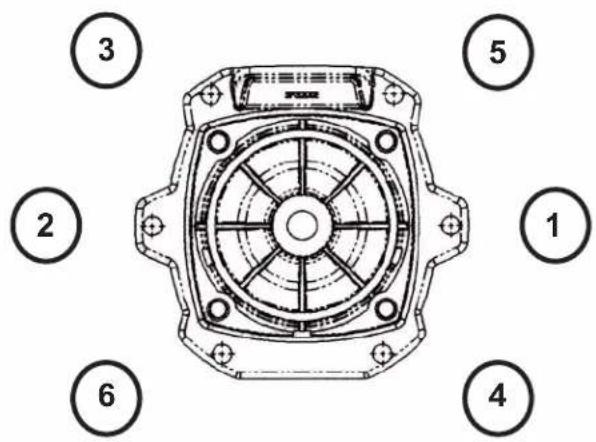
Ordre de serrage des boulons - Bolt tightening order - Orden de apriete de los pernos - Ordem de aperto dos parafusos - Anzugsreihenfolge der Bolzen - Volgorde waarin de bouten vastgedraaid moeten worden - Ordine di stringimento bulloni - Ordning för att dra åt bultarna - Spændngsrækkefølge for bolte - Rekkefølge for tiltrekking av boltene - Pulttien kirstysjärjestys - Порядок затяжки болтов
185 INCH LBS
20.9 N m
K-FLO VSTD SERIES
SPK12615VSTD
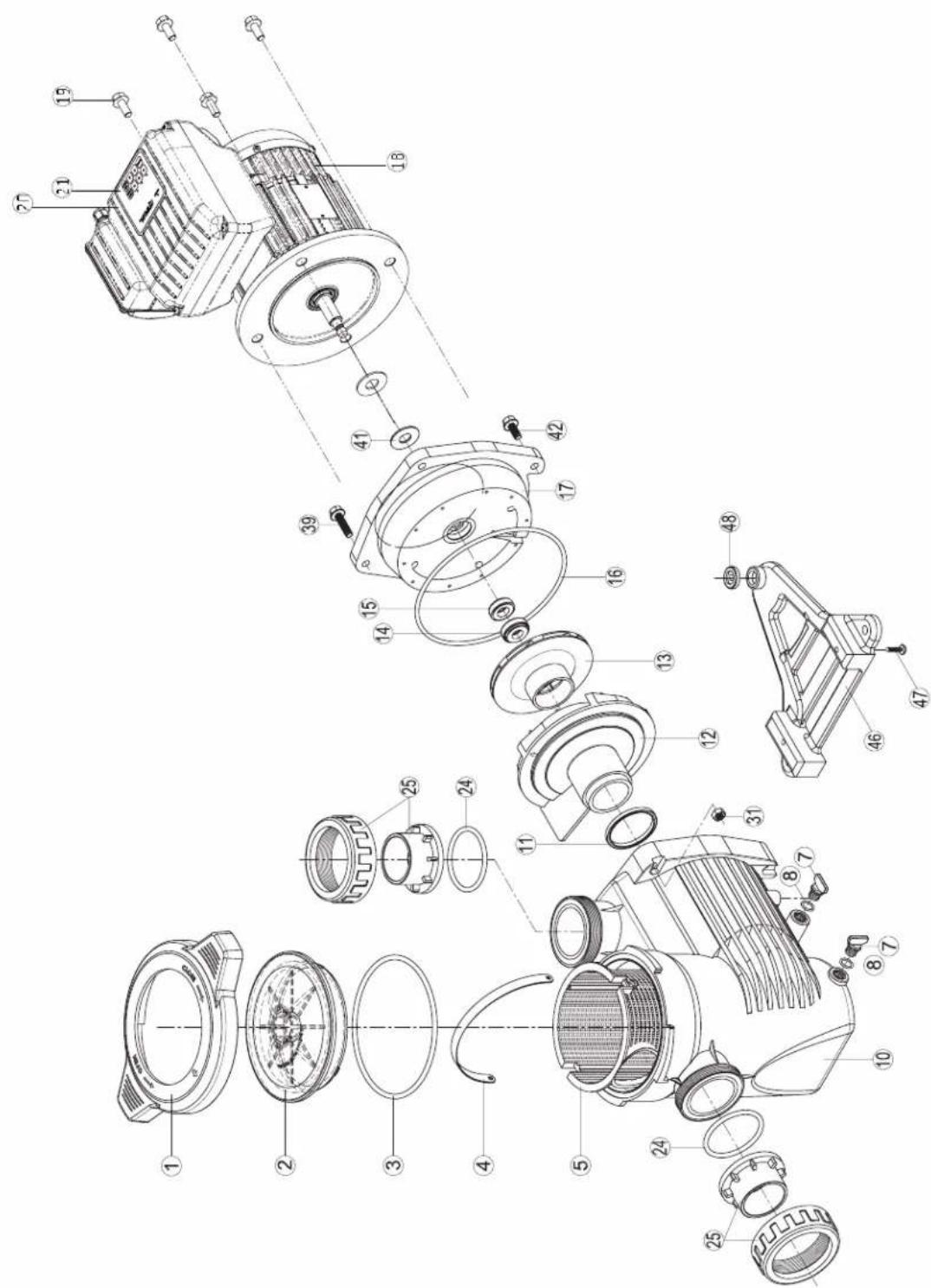
| N° | Description · Description · Descripción · Descrição · Bezeichnung · Beschrijving · Descrizione · Beskrivning · Beskrivelse · Beskrivelse · Kuvaus · Описание |
| 1 | Locking nut · Écrou couvercle préfiltre · Tuerca de cierre · Porca da tampa do pré-filtro · Mutter Vorfilterdeckel · Moer deksel voorfilter · Dado coperchio prefiltro · Läsmutter · Läsemutter · Läsemøtrik · Lukitusmutteri · Гайка крышки грубой фильтрации |
| 2 | Cover kit (cover + o-ring) · Kit couvercle (couvercle + joint torique) · Conjunto tapa + junta · Kit da tampa (tampa + junta tórica) · Deckelset (Deckel + O-Ring) · Dekselset (deksel + O-ring) · Kit coperchio (coperchio + guarnizione torica) · Skydssats (hölje + o-ring) · Dekselsett (deksel + o-ring) · Dæksæt (cover + o-ring) · Kansisarja (kansi + O-rengas) · Комплект крышки (крышка + кольцевое уплотнение) |
| 3 | Cover o-ring · Joint torique couvercle · Junta de tapa · Junta tórica da tampa · O-Ring Deckel · O-ring van deksel · Guarnizione torica coperchio · Täck o-ring · Dekk o-ring · Dæk o-ring · Kannen O-rengas · Кольцевое уплотнение крышки |
| 4+5 | Strainer basket · Panier de préfiltre · Cestillo prefiltro · Cesto do pré-filtro · Vorfilterkorb · Mand van voorfilter · Cesto prefiltro · Silkorg · Sil kurv · Si kurv · Siivilä kori · Малая корзина грубой фильтрации |
| 7+8 | Drain kit · Kit vidange · Kit tapon desague · Kit de vazamento · Entleerungsset · Aftapset · Kit di spurgo · Avloppssats · Avlopssett · Afløbs-sæt · Viemärisarja · Набор опорожнения |
| 3+8+11+16+24 | Pump gasket kit · Jeu complet de joints pompe · Juego completo juntas · Jogo completo de juntas da bomba · Kompletter Satz Pumpen-dichtungen · Compleet set van pompringen · Set completo di guarnizioni pompa · Pumppackningssats · Pumpepakningssett · Pumpepak-ningssæt · Pumpun tiivistesarja · Полный набор уплотнений для насоса |
| 10 | Pump casing · Corps de pompe · Cuerpo de bomba · Corpo da bomba · Pumpengehäuse · Pomphuis · Corpo della pompa · Pumphus · Pumpehus · Pumpehus · Pumpun kotelo · Корпус насоса |
| 11 | Diffuser o-ring · Joint torique de diffuseur · Junta difusor · Junta tórica do difusor · O-Ring Diffusor · O-ring van diffusor · Guarnizione torica diffusore · Diffusor o-ring · Diffusor o-ring · Diffusor o-ring · Hajottimen O-rengas · Кольцевое уплотнение диффузора |
| 12 | Diffuser · Diffuseur · Difusor · Difusor · Diffusor · Diffusor · Diffusor · Spreder · Diffuser · Hajotin · Диффузор |
| 13 | Impeller VS 1,5HP · Turbine VS 1,5 CV · Rodete VS 1,5 CV · Turbina VS 1,5 CV · Turbine VS 1,5 PS · Rotor VS 1,5 PK · Turbina VS 1,5 CV · Impeller VS 1,5HP · Impeller VS 1,5HK · Løbehjul VS 1,5HK · Juoksupyörä VS 1,5hv · Турбина VS 1,5 л.с. |
| 14+15 | Mechanical seal kit · Garniture mécanique · Conjunto retén · Vedação mecânica · Mechanische Dichtung · Mechanische dichtingen · Tenuta meccanica · Mekanisk tätningssats · Mekanisk tetningssett · Mekanisk tætningssæt · Mekaaninen tiivistesarja · Механическое уплотнение |
| 16 | Casing flange o-ring · Joint plateau d'étanchéité · Junta cuerpo union · Junta do disco de vedação · Dichtung Dichtplatte · O-ring af-dichtingsflens · Guarnizione flangia · Husfläns o-ring · Husflens o-ring · Husflange o-ring · Kotelon laipan O-rengas · Прокладка уплотнительной пластины |
| 17 | Casing flange · Plateau d'étanchéité · Cuerpo union · Disco de vedação · Dichtplatte · Afdichtingsflens · Flangia di tenuta · Husfläns · Hus-flens · Husflange · Kotelon laippa · Уплотнительная пластина |
| 18 | Motor 1.5HP VS · Moteur 1,5 CV VS · Motor 1,5 CV VS · Motor 1,5 PS VS · Motor 1,5 PK VS · Motore 1,5 CV VS · Motor 1,5 hk VS · Motor 1,5HK VS · Motor 1,5HK VS · Moottori 1,5hv VS · Двигатель 1,5 л.с. VS |
| 19 | Gland · Presse-étoupe · Prensa estopas · Bucim de empanque · Stopfbüchse · Pakkingbus · Pressacavo · Körtel · Kjertel · Kirtel · Gland · Уплотненный кабельный ввод |
| 20 | Electronic module · Module électronique · Modulo electronico · Módulo eletrónico · Elektronikmodul · Elektronische module · Modulo elet-tronico · Elektronisk modul · Elektronisk modul · Elektronink moduli · Электронный модуль |
| 21 | User interface VSTD · Interface utilisateur VSTD · Interfaz de usuario VSTD · Пользовательский интерфейс VSTD · Benutzerschnittstelle VSTD · Interface do utilizador VSTD · Interfaccia utente VSTD · Gebruikersinterface VSTD · Användargränssnitt VSTD · Brukergrensesnitt VSTD · Brugergrænseflade VSTD · Käyttöliittymä VSTD · |
| 24+25 | Set of unions · Kit raccord union · Kit enlaces · Kit de unioes de ligacao · Verschraubungssatz · Set koppelstukken · Kit raccordi di collega-mento · Uppsättning av fackföreningar · Sett med fagforeninger · Sæt af fagforeninger · Joukko ammattiliittoja · Набор соединения union |
| 31+39+42+47 | Hardware kit · Kit visserie · Kit tornilleria completa · Kit de peças de fixação · Schraubensatz · Schroeven en moeren · Kit bulloneria · Hårdvarusats · Maskinvaresett · Hardware sæt · Laitteistosarja · Комплект резьбовых деталей |
| 41 | Slinger · Pare-goutte · Paragotero · Anel defletor · Tropfschutz · Morsring · Anello paracqua · Slinger · Slinger · Slinger · Slinger · Slinger · Kanельное кольцо |
| 46+48 | Pump support · Support de pompe · Base de bomba · Suporte da bomba · Pumpenträger · Pompbasis · Supporto della pompa · Pumpstöd · Pumpestøtte · Pumpestøtte · Pumpun tuki · Onopa насоса |
| - | Fan HG 0,50-1,50HP M · Ventilateur HG 0,50-1,50 CV M · Ventilador HG 0,50-1,50 CV M · Ventoinha HG 0,50-1,50 CV M · Lüfter HG 0,50-1,50 PS M · Ventilator HG 0,50-1,50 PK M · Ventilatore HG 0,50-1,50 CV M · Flåkt HG 0,50-1,50HP M · Vifte HG 0,50-1,50 HK M · Ventilator HG 0,50-1,50HK M · Tuuletin HG 0,50-1,50HP M · Вентилятор HG 0,50-1,50 л.с. М |
| - | Fan cover VS · Capot ventilateur VS · Tapa ventilador VS · Tampa da ventoinha VS · Lüfterabdeckung VS · Ventilatorkap VS · Coperchio ventilatore VS · Fläktkäpa VS · Viftedeksel VS · Ventilatordäksel VS · Tuulettimen kansi VS · Крышка вентилятора VS |
| - | Bearings kit Motor RF 1 · Kit roulements moteur RF 1 · Kit rodamientos Motor RF 1 · Kit de rolamientos do motor RF 1 · Lagerset Motor RF 1 · Set lagers voor motor RF 1 · Kit cuscinetti motore RF 1 · Lagersats Motor RF 1 · Lagersæt Motor RF 1 · Lejesæt Motor RF 1 · Laakeri-sarja Moottori RF 1 · Набор подшипников двигателя RF 1 |
RS II VSTD SERIES
RS3016VSTD
RS3020VSTD
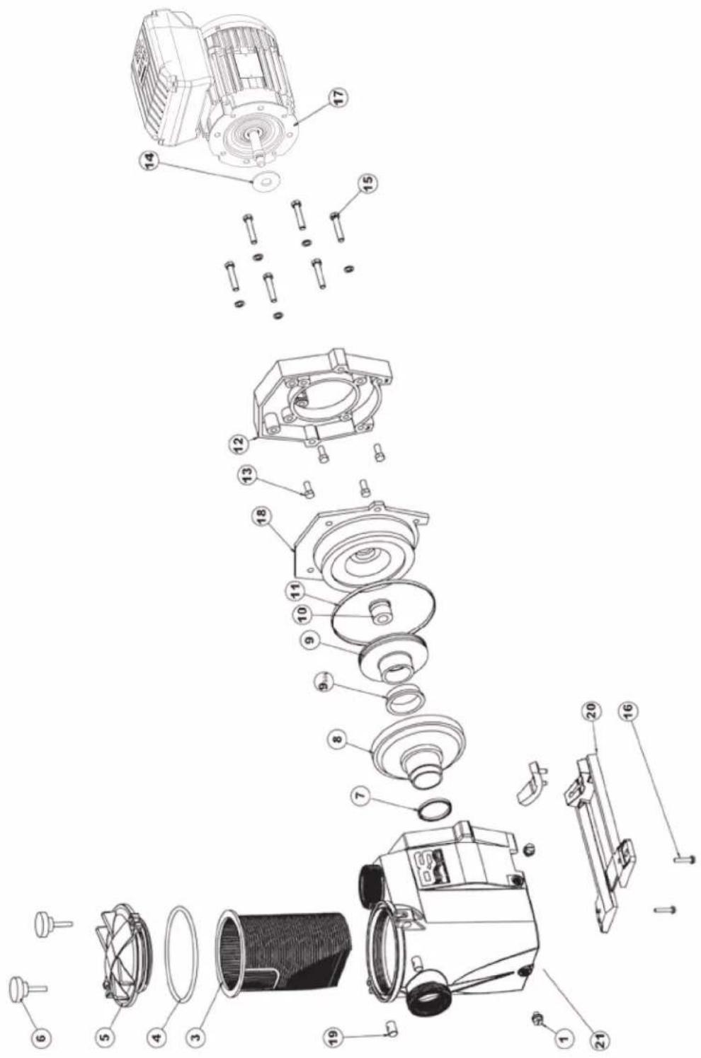
| No | Description - Description - Descripción - Descrição - Bezeichnung - Beschrijving - Descrizione - Beskrivning - Beskrivelse - Beskrivelse - Kuvaus - Описание |
| 1 | Drain Plug · Bouchon de vidange · Tapón de vaciado · Plugue de dreno · Ablasschraube · Afvoerkanaal stop · Tappo di spurgo · Avtapp-ningsplugg · Dreneringsplugg · Bundprop · Tyhjennystulppa · Комплект сливных пробок |
| 3 | Strainer basket · Panier de préfiltre · Cesto filtrante · Cesta do filtro · Filterkorb · Zeef mand · Cestino prefiltro · Silkorg · Sil kurv · Si kurv · Siivilä kori · Корзина префильтра |
| 4 | Strainer cover O-Ring · Joint torique · Junta tórica · Уплотнительное кольцо · O-Ring · De O-ring van de zeefdekking · O-Ring de tampa do filtro · Guarnizione O'ring · Silskydd O-ring · Sildeksel O-Ring · Sidæksel O-ring · Siivilä kannen O-rengas · |
| 5 | Strainer cover · Couvercle de préfiltre · Tapa de prefiltro · Tampa do filtro · Deckel · Zeef dekking · Coperchio prefiltro · Silskydd · Sildeksel · Si dæksel · Siivilä kansi · Крышка префильтра |
| 7 | Diffuser gasket · Joint de diffuseur · Junta de difusor · Junta de difusor · Dichtung · Verbindingsstuk van verspreider · Guarnizione diffusore · Diffusor packing · Diffuserpakning · Diffuser pakning · Hajottimen tiiviste · Прокладка |
| 8 | Diffuser · Diffuseur · Difusor · Difusor · Leitapparat · Verspreide · Diffusore · Diffusor · Spreader · Diffuser · Hajotin · Диффузор |
| 9 | Impeller · Turbine · Turbina · Turbina · Laufrad · Turbine · Girante · Impeller · Impeller · Løbehjul · Juoksupyörä · Крыльчатка |
| 9 bis | Ring for impeller · Bague pour turbine · Anillo para turbina · Anel para turbina · Ring für Laufrad · Ring voor Turbine · Anello · Ring för pum-phjul · Ring for impeller · Ring til pumpehjul · Rengas juoksupyörälle · Уплотнительное кольцо |
| 10 | Seal assembly · Obturateur mécanique · Cierre mecánico · Conjunto de selo · Motorhalterung · Verbindings assemblage · Tenuta meccanica · Tätningsmontering · Tetningsmontering · Tætningssamling · Tiivisteen kokoonpano · Сальник в сборе |
| 11 | Housing gasket · Joint de corps · Junta · Gaxeta da carcaça · Dichtung · Huisvestings pakking · Guarnizione corpo · Huspackning · Hus-pakning · Huspakning · Kotelon tiiviste · Прокладка |
| 12 | Motor mounting plate · Support moteur · Soporte motor · Apoio a motor · Motorhalterung · Motorsteun · Supporto motore · Motor monte-ringsplatta · Motor monteringsplate · Motor monteringsplade · Moottorin asennuslevy · Фланец электродвигателя |
| 13 | Motor cap screw · Vis moteur · Tornillo · Tornillos a motor · Sechskrantschraube · Schroef motor · Viti · Motorskruv · Motorskrue · Motor hætteskrue · Moottorin kannen ruuvi · Комплект винтов |
| 14 | Slinger · Larmier · Arandela Separación · Arandela Separación · Tropfing · Tropfing · Rondella di separazione · Slinger · Slinger · Slinger · Маспосъемное кольцо |
| 15 | Housing cap screws · Vis corps de pompe · Tornillo cabeza exagonal · Tornillos de tampão da carcaça · Sechskantschraube · Huisvestings GLB schroeven · Viti a testa esagonale · Kåpans skruvar · Husets hodeskruer · Husets hætteskruer · Kotelon kannen ruuvit · Комплект винтов |
| 16 | Cap screw · Vis support de pompe · Tornillo cabeza exagonal · Tornillos apoio de bomba · Sechskanschraube · Schroef steun van pomp · Viti · Kapselskruv · Toppskrue · Skruelåg · Kantaruuvi · Комплект винтов |
| 17 | Motor · Moteur · Motor · Motor · Motor · Motore · Motor · Motor · Moottori · Электродвигатель |
| 18 | Seal plate · Plateau d'étanchéité · Plato de cierre · Placa do selo · Flansch · Verbindings plaa · Supporto di fissaggio · Tätningsplatta · Forseglingsplate · Tætningsplade · Tiivistelevy · Фланец |
| 19+6 | Swivel nut + Hand knob · Ecrou rotule + Vis papillon · Rótula + Tornillo maripo · Tuerca de giro+ Parafuso borboleta · Gewindezapfen + Flügelschraube · Wartel noot + Schroef vlinder · Perno Manopola di chiusura · Svängmutter + Handknopp · Svingmutter + håndknapp · Drejemøtrik + Håndknop · Kääntömutteri + käsinuppi · Комплект втулок и винтов |
| 20 | Mounting bracket · Support de pompe · Soporte bomba · Suporte de montagem · Sockelteil · Opzettende steun · Supporto pompa · Monte-ringsfäste · Monteringsbrakett · Monteringsbeslag · Kiinnike · Монтажная стойка |
| 21 | Assembly Body RS II (body, basket, cover, feet) · Corps assemblé RS II (Corps, panier, couvercle, pieds) · Cuerpo montado RS II (cuerpo, cesta, tapa, pie) · Corpo armado RSII (corpo, cesto, tampa, pé) · Zusammengesetzler körper RS II (körper, korb, deckel, fub) · Assemblage lichaam RS II (Lichaam, Zeef mand, Zeef dekking,Voeten) · Corpo riunito RS II (corpo, canestro, coperchio, piede) · Monteringskropp RS II (kropp, korg, lock, fötter) · Monteringskropp RS II (kropp, kurv, deksel, fötter) · Samlingskrop RS II (krop, kurv, dæksel, fødder) · Asennus-runko RS II (runko, kori, kansi, jalat) · Корпус насоса в |
| 4+7+10+1114 | Set of gaskets · Pack de joints · Juego de juntas · Conjunto de juntas · Satz Dichtungen · Set van pakkingen · Set di guarnizioni · Uppsätt-ning packningar · Sett med pakninger · Sæt med pakninger · Tiivistesarja · Комплект прокладок |
MAX FLO XL VSTD SERIES
SP2310VSTD
SP2315VSTD
| No | Description · Description · Descripción · Descripción · Bezeichnung · Beschrijving · Descrizione · Beskrivning · Beskrivelse · Beskrivelse · Kuvaus · Описание |
| 1 | Locking nut · Écrou couvercle préfiltre · Tuerca de cierre · Porca da tampa do pré-filtro · Mutter Vorfilterdeckel · Moer deksel voorfilter · Dado coperchio prefiltro · Läsmutter · Läsemutter · Läsemøtrik · Lukitusmutteri · Гайка крышки грубой фильтрации |
| 2+3 | Cover kit (cover + o-ring) · Kit couvercle (couvercle + joint torque) · Conjunto tapa + junta · Kit da tampa (tampa + junta tórica) · Deckelset (Deckel + O-Ring) · Dekselset (deksel + O-ring) · Kit coperchio (coperchio + guarnizione torica) · Skyddssats (hölje + o-ring) · Dekselsett (deksel + o-ring) · Dæksæt (cover + o-ring) · Kansisarja (kansi + O-rengas) · Комплект крышки (крышка + кольцевое уплотнение) |
| 3 | Cover o-ring · Joint torque couvercle · Junta de tapa · Junta tórica da tampa · O-Ring Deckel · O-ring van deksel · Guarnizione torica coperchio · Täck o-ring · Dekk o-ring · Dæk o-ring · Kannen O-rengas · Кольцевое уплотнение крышки |
| 4+5 | Strainer basket · Panier de préfiltre · Cestillo prefiltro · Cesto do pré-filtro · Vorfilterkorb · Mand van voorfilter · Cesto prefiltro · Silkorg · Sil kurv · Si kurv · Siivilä kori · Малая корзина грубой фильтрации |
| 7+8 | Drain kit · Kit vidange · Kit tapon desague · Kit de vazamento · Entleerungsset · Aftapset · Kit di spurgo · 7+8 Avloppssats · 7+8 Avløpssett · 7+8 Aføbssæt · 7+8 Viemārisarja · Набор опорожнения |
| 3+8+11+1624 | Pump gasket kit · Jeu complet de joints pompe · Juego completo juntas · Jogo completo de juntas da bomba · Kompletter Satz Pumpendichtungen · Compleet set van pompringen · Set completo di guarnizioni pompa · Pumpackningssats · Pumpepakningssett · Pumpepakningssæt · Pumpun tiivistesarja · Полный набор уплотнений для насоса |
| 10 | Pump casing · Corps de pompe · Cuerpo de bomba · Corpo da bomba · Pumpengehäuse · Pomphuis · Corpo della pompa · Pumphus · Pumpehus · Pumpehus · Pumpun kotelo · Корпус насоса |
| 11 | Diffuser o-ring · Joint torque de diffuseur · Junta difusor · Junta tórica do difusor · O-Ring Diffusor · O-ring van diffusor · Guarnizione torica diffusore · Diffusor o-ring · Diffusor o-ring · Hajottimen O-rengas · Кольцевое уплотнение диффузора |
| 12 | Diffuser · Diffuseur · Difusor · Difusor · Diffusor · Diffusore · Diffusor · Spreader · Diffuser · Hajotin · Диффузор |
| 13 | Impeller VS 1,5HP · Turbine VS 1,5 CV · Rodele VS 1,5 CV · Turbina VS 1,5 CV · Turbine VS 1,5 PS · Rotor VS 1,5 PK · Turbina VS 1,5 CV · Impeller VS 1,5HP · Impeller VS 1,5HK · Lebehjul VS 1,5HK · Juoksupyörä VS 1,5hv · Турбина VS 1,5 л.с. |
| 14+15 | Mechanical seal kit · Garniture mécanique · Conjunto retén · Vedação mecânica · Mechanische Dichtung · Mechanische dichtingen · Tenuta meccanica · Mekanisk tätningssats · Mekanisk tetningssett · Mekanisk tætningssæt · Mekaaninen tiivistesarja · Механическое уплотнение |
| 16 | Casing flange o-ring · Joint plateau d'étanchéité · Junta cuerpo union · Junta do disco de vedação · Dichtung Dichtplatte · O-ring af-dichtingsflens · Guarnizione flangia · Husfläns o-ring · Husflens o-ring · Husflange o-ring · Kotelon laipan O-rengas · Прокладка уплотнительной пластины |
| 17 | Casing flange · Plateau d'étanchéité · Cuerpo union · Disco de vedação · Dichtplatte · Afdichtingsflens · Flangia di tenuta · Husfläns · Hus-flens · Husflange · Kotelon laippa · Уплотнительная пластина |
| 18+48 | Pump support · Support de pompe · Base de bomba · Suporte da bomba · Pumpenträger · Pompbasis · Supporto della pompa · Pumpstöd · Pumpestøtte · Pumpestøtte · Pumpun tuki · Onopa насоса |
| 18 | Motor 1.5HP VS · Moteur 1,5 CV VS · Motor 1.5 CV VS · Motor 1,5 CV VS · Motor 1,5 PS VS · Motor 1,5 PK VS · Motore 1,5 CV VS · Motor 1,5 hk VS · Motor 1,5HK VS · Motor 1,5HK VS · Moottori 1,5hv VS · Двигатель 1,5 л.с. VS |
| 19 | Gland · Presse-étoupe · Prensa estopas · Bucim de empanque · Stopfbüchse · Pakkingbus · Pressacavo · Körtel · Kjertel · Kirtel · Gland · Уплотненный кабельный ввод |
| 20 | Electronic module · Module électronique · Modulo electronico · Módulo eletrónico · Elektronikmodul · Elektronische module · Modulo elet-tronico · Elektronisk modul · Elektronisk modul · Elektronink moduli · Электронный модуль |
| 21 | User interface VSTD · Interface utilisateur VSTD · Interfaz de usuario VSTD · Interface do utilizador VSTD · Benutzerschnittstelle VSTD · Gebruikersinterface VSTD · Interfaccia utente VSTD · Användargränssnitt VSTD · Brukergrensesnitt VSTD · Brugergrænseflade VSTD · Käyttöliittymä VSTD · Пользовательский интерфейс VSTD |
| 24+25 | Set of unions · Kit raccord union · Kit enlaces · Kit de unions de ligacao · Verschraubungssatz · Set koppelstukken · Kit raccordi di collega-mento · Uppsättning av fackföreningar · Sett med fagforeninger · Sæt af fagforeninger · Joukko ammattiliittoja · Набор соединения union |
| 31+39+42+47 | Hardware kit · Kit visserie · Kit tornilleria completa · Kit de peças de fixação · Schraubensatz · Schroeven en moeren · Kit bulloneria · Härd-varusats · Maskinvaresett · Hardware sæt · Laitteistosarja · Комплект резьбовых деталей |
| 41 | Slinger · Pare-goutte · Paragotero · Anel defletor · Tropfschutz · Morsring · Anello paracqua · Slinger · Slinger · Slinger · Slinger · Капельное кольцо |
| - | Fan HG 0,50-1.50HP M · Ventilateur HG 0,50-1,50 CV M · Ventilador HG 0,50-1.50 CV M · Ventoinha HG 0,50-1.50 CV M · Lüfter HG 0,50-1,50 PS M · Ventilator HG 0,50-1,50 PK M · Ventilatore HG 0,50-1,50 CV M · Fläkt HG 0,50-1,50HP M · Vifte HG 0,50-1,50 HK M · Ventilator HG 0,50-1,50HK M · Tuuletin HG 0,50-1,50HP M · Вентилятор HG 0,50-1,50 л.с. М |
| - | Fan cover VS · Capot ventilateur VS · Tapa ventilador VS · Tampa da ventoinha VS · Lüfterabdeckung VS · Ventilatorkap VS · Coperchio ventilatore VS · Fläktkåpa VS · Viftedeksel VS · Ventilatordæksel VS · Tuulettimen kansi VS · Крышка вентилятора VS |
| - | Bearings kit Motor RF 1 · Kit roulements moteur RF 1 · Kit rodamientos Motor RF 1 · Kit de rolamentos do motor RF 1 · Lagerset Motor RF 1 · Set lagers voor motor RF 1 · Kit cuscinetti motore RF 1 · Lagersats Motor RF 1 · Lagersett Motor RF 1 · Lejesæt Motor RF 1 · Laakerisarja Moottori RF 1 · Набор подшипников двигателя RF 1 |
Ordre de serrage des boulons - Bolt tightening order - Orden de apriete de los pernos - Ordem de aperto dos parafusos - Anzugsreihenfolge der Bolzen - Volgorde waarin de bouten vastgedraaid moeten worden - Ordine di stringimento bulloni - Ordning för att dra åt bultarna - Spændngsrækkefølge for bolte - Rekkefølge for tiltrekking av boltene - Pulttien kirstysjärjestys - Порядок затяжки болтов
185 INCH LBS
20.9 N m
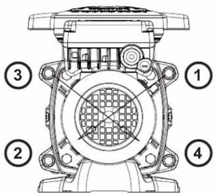
SUPERPUMP VSTD
SP2611VSTD
SP2616VSTD
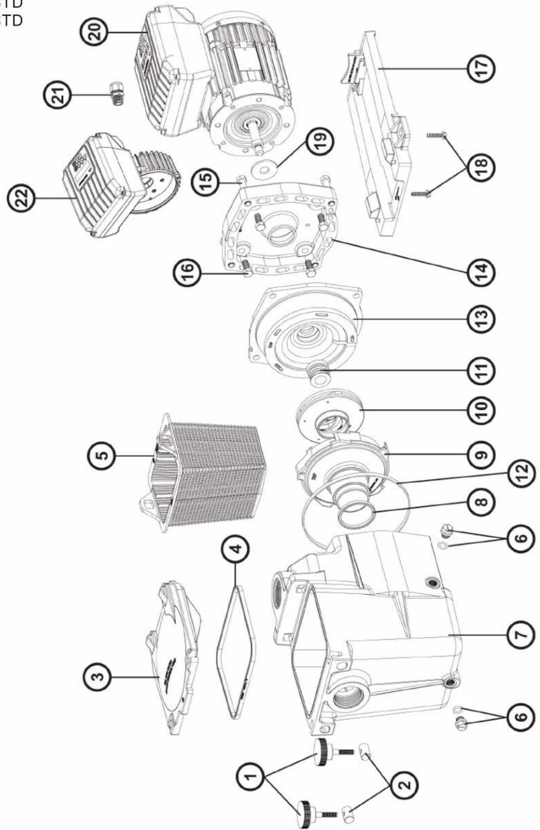
| N° | Description · Description · Descripción · Descrição · Bezeichnung · Beschrijving · Descrizione · Beskrivning · Beskrivelse · Beskrivelse · Kuvaus · Описание |
| 1+2 | Swivel nut + Hand knob · Ecrou rotule + Vis papillon · Rótula + Tornillo mariposa · Tuerca de giro+ Parafuso borboleta · Gewindezapfen + Flügelschraube · Wartel noot + Schroef vlinder · Perno girevole + Manopola di chiusura · Svängmutter + Handknopp · Svingmutter + håndknapp · Drejemøtrik + Håndknop · Kääntömutteri + käsinuppi · Комплект втулок и винтов |
| 3 | Strainer cover · Couvercle de préfiltre · Tapa de prefiltro · Tampa do filtro · Deckel · Zeef dekking · Coperchio prefiltro · Silskydd · Sildeksel · Si dæksel · Siivilä kansi · Крышка префильтра |
| 4 | Lid gasket · Joint de préfiltre · Junta de prefiltro · Junta préfiltre · Dichtung · Verbindingsstuk van préfiltre · Guarnizione prefiltro · Lockets packing · Lokkpakning · Lågpakning · Kannen tiiviste · Прокладка |
| 5 | Strainer basket · Panier de préfiltre · Cesto filtrante · Cesta do filtro · Filterkorb · Zeef mand · Cestino prefiltro · Silkorg · Sil kurv · Si kurv · Siivilä kori · Корзина префильтра |
| 6 | Drain Plug · Bouchon de vidange · Tapón de vaciado · Plugue de dreno · Ablasschraube · Afvoerkanaal stop · Tappo di spurgo · Avtappningsplugg · Dreneringsplugg · Bundprop · Tyhjennystulppa · Комплект сливных пробок |
| 7 | Pump Housing/Strainer · Corps de pompe et préfiltre · Cuerpo bomba y prefiltro · Corpo de bomba e préfiltre · Pumpengehäuse/Vorfilter · Lichaam van pomp en préfiltre · Corpo pompa/ Prefiltro · Pumphus/sil · Pumpehus/sil · Pumpehus/si · Pumpun kotelo/siivilä · Kopnyc насoca |
| 8 | Diffuser gasket · Joint de diffuseur · Junta de difusor · Junta de difusor · Dichtung · Verbindingsstuk van verspreider · Guarnizione diffusore · Diffusor packing · Diffuserpakning · Diffuser pakning · Hajottimen tiiviste · рокладка |
| 9 | Diffuser · Diffuseur · Difusor · Difusor · Leitapparat · Verspreide · Diffusore · Diffusor · Spreader · Diffuser · Hajotin · Диффузор |
| 10 | Impeller · Turbine · Turbina · Turbina · Laufrad · Turbine · Girante · Impeller · Impeller · Løbehjul · Juoksupyörä · Крыльчатка |
| 11 | Seal assembly · Obturateur mécanique · Cierre mecânico · Conjunto de selo · Motorhalterung · Verbindings assemblage · Tenuta meccanica · Tätningsmontering · Tetningsmontering · Tætningssamling · Tiivisteen kokoonpano · Сальник в сборе |
| 12 | Housing gasket · Joint de corps · Junta · Gaxeta da carcaça · Dichtung · Huisvestings pakking · Guarnizione corpo · Huspackning · Huspakning · Huspakning · Kotelon tiiviste · Прокладка |
| 13+14 | Seal plate+Motor mounting plate · Plateau d'etancheite+Support moteur · Plato de cierre+Soporte motor · Placa do selo+Apoio a motor · Flansch+Motorhalterung · Verbindings plaat+Motorsteun · Supporto di fissaggio+Supporto motore · Tätningsplatta+Motormonteringsplatta · Tetningsplate+Motormonteringsplate · Tætningsplade+Motor monteringsplade · Tiivistelevy + moottorin asennuslevy · Фланец+Фланец электродвигателя |
| 15 | Housing screw · Vis plateau d'étanchéité · Tornillo de cabeza hexagonal · Tornillos de carcaça · Sechskantschraube · Huisvestings schroeven · Viti esagonali · Husskruv · Husskrue · Husskrue · Kotelon ruuvi · Набор винтов |
| 16 | Motor cap screw · Vis moteur · Tornillo · Tornillos a motor · Sechskrantschraube · Schroef motor · Viti · Motorskruv · Motorskrue · Motor hætteskrue · Moottorin kannen ruuvi · Набор винтов |
| 17 | Mounting bracket · Support de pompe · Soporte bomba · Suporte de montagem · Sockelteil · Opzettende steun · Supporto pompa · Monte-ringsfäste · Monteringsbrakett · Monteringsbeslag · Kiinnike · Монтажная стойка |
| 18 | Cap screw · Vis support de pompe · Tornillo cabeza exagonal · Parafuso apoio de bomba · Sechskanschraube · Schroef steun van pomp · Viti · Kapselskruv · Toppskrue · Skruelåg · Kantaruuvi · Набор винтов |
| 19 | Slinger · Larmier · Arandela Separación · Arandela Separación · Tropfing · Tropfing · Rondella di separazione · Slinger · Slinger · Slinger · Slinger · Маслосьемное кольцо |
| 20 | Motor · Moteur · Motor · Motor · Motor · Motore · Motor · Motor · Motore · Moottori · Электродвигатель |
| 21 | Gland · Presse étoupe · Prensa estopas · Imprensa estopa · Kabel-Klemme · Klier · Pressacavo · Körtel · Kjertel · Kirtel · Gland · Сальник 1 SPX1100PE 71,19 |
| 22 | Electronic module · Module électronique · Módulo electrónico · Módulo electrónico · Elektronik-Modul · Elektronische module · Modulo elettronico · Elektronisk modul · Elektronisk modul · Elektronisk modul · Elektroninen moduuli · Электронный модуль |
| 23 | User interface · Interface utilisateur · interfaz de usuario · Interface do usuário · Benutzerschnittstelle · gebruikersinterface · interfaccia utente · Användargränssnitt · Brukergrensesnitt · brugergrænseflade · Käyttöliittymä · интерфейс пользователя |
| 4+8+11+12+19 | Set of gaskets · Pack de joints · Juego de juntas · Conjunto de juntas · Satz Dichtungen · Set van pakkingen · Set di guarnizioni · Uppsättning packningar · Sett med pakninger · Saet med pakninger · Tiivistesarja · Комплект прокладок |
| - | Fan · Ventilateur · Ventilador · Fan · Fan · Ventilador · Fan · Fläkt · Fan · Ventilator · Tuuletin · вентилятор |
| - | Fan cover · Capot ventilateur · Cubierta del ventilador · Ventilatordeksel · Lüfterhaube · Fan cobertura · Copriventola · Fläktkäpa · Vift-edeksel · Ventilatordæksel · Tuulettimen kansi · Кожух вентилятора |
| - | Motor Bearings Kit · Kit Roulements moteur · Kit de rodamientos de motor · Kit rolamentos do motor · Motorlager-Kit · Motorlagers kit · Kit cuscinetto del motore · Motorlagersats · Motorlagersett · Motor lejesæt · Moottorin laakerit · Подшипники двигателя комплект |
| - | Superpump 2" male to 1,5" female retrofit kit · Superpump 2" / 1,5" kit adaptateur · Superpump kit adaptador 2" / 1,5" · Superpump kit adaptador 2" / 1,5" · Superpump 2" / 1,5" adapter-Kit · Superpump 2" / 1,5" adapter-kit · Superpump kit adattatore 2" / 1,5" · Superpump 2" hane till 1,5" hona eftermonteringssats · Superpump 2" hann til 1,5" hun ettermonteringsett · Superpump 2" han til 1,5" hun eftermonteringssæt · Superpump 2" uros-1,5" naaras jälkiasennussarja · Комплект переходников Superpump 2" / 1,5" |
E-FLO VSTD SERIES
EFLO126115VSTD
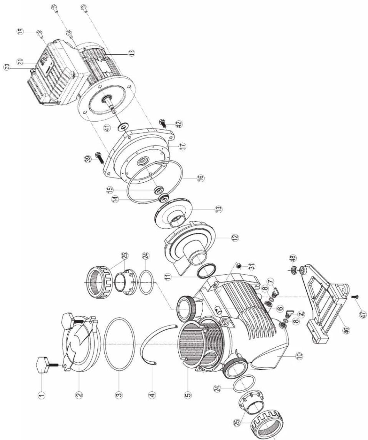
| N° | Description · Description · Descripción · Descrição · Bezeichnung · Beschrijving · Descrizione · Beskrivning · Beskrivelse · Beskrivelse · Kuvaus · Описание |
| 1 | Locking nut · Écrou couvercle préfiltre · Tuerca de cierre · Porca da tampa do pré-filtro · Mutter Vorfilterdeckel · Moer deksel voorfilter · Dado coperchio prefiltro · Läsmutter · Läsemutter · Läsemøtrik · Lukitusmutteri · Гайка крышки грубой фильтрации |
| 2 | Cover · Couvercle · Tapa · Tampa · Deckel · Deksel · Coperchio · Hölje · Deksel · Cover · Kansi · Крышка |
| 3 | Cover o-ring · Joint torique couvercle · Junta de tapa · Junta tórica da tampa · O-Ring Deckel · O-ring van deksel · Guarnizione torica coperchio · Täck o-ring · Dekk o-ring · Dæk o-ring · Kannen O-rengas · Кольцевое уплотнение крышки |
| 4+5 | Strainer basket · Panier de préfiltre · Cestillo prefiltro · Cesto do pré-filtro · Vorfilterkorb · Mand van voorfilter · Cesto prefiltro · Silkorg · Sil kurv · Si kurv · Siivilä kori · Малая корзина грубой фильтрации |
| 7+8 | Drain kit · Kit vidange · Kit tapon desague · Kit de vazamento · Entleerungsset · Aftapset · Kit di spurgo · Avloppssats · Avlopsettett · Afløbs-sæt · Viemärisarja · Набор опорожнения |
| 3+8+11+16+24 | Pump gasket kit · Jeu complet de joints pompe · Juego completo juntas · Jogo completo de juntas da bomba · Kompletter Satz Pumpen-dichtungen · Compleet set van pompringen · Set completo di guarnizioni pompa · Pumpackningssats · Pumpepakningssett · Pumpepak-ningssæt · Pumpun tiivistesarja · Полный набор уплотнений для насоса |
| 10 | Pump casing · Corps de pompe · Cuerpo de bomba · Corpo da bomba · Pumpengehäuse · Pomphuis · Corpo della pompa · Pumphus · Pumpehus · Pumpehus · Pumpun kotelo · Kopnyc насоса |
| 11 | Diffuser o-ring · Joint torique de diffuseur · Junta difusor · Junta tórica do difusor · O-Ring Diffusor · O-ring van diffusor · Guarnizione torica diffusore · Diffusor o-ring · Diffusor o-ring · Hajottimen O-rengas · Кольцевое уплотнение диффузора |
| 12 | Diffuser · Diffuseur · Difusor · Difusor · Diffusor · Diffusor · Diffusor · Spreader · Diffuser · Hajotin · Диффузор |
| 13 | Impeller VS 1,5HP · Turbine VS 1,5 CV · Rodete VS 1,5 CV · Turbine VS 1,5 CV · Turbine VS 1,5 PS · Rotor VS 1,5 PK · Turbina VS 1,5 CV · Impeller VS 1,5HP · Impeller VS 1,5HK · Løbehjul VS 1,5HK · Juoksupyörä VS 1,5hv · Турбина VS 1,5 л.с. |
| 14+15 | Mechanical seal kit · Garniture mécanique · Conjunto retén · Vedação mecânica · Mechanische Dichtung · Mechanische dichtingen · Tenuta meccanica · Mekanisk tätningssats · Mekanisk tetningssett · Mekanisk tätningssæt · Mekaaninen tiivistesarja · Механическое уплотнение |
| 16 | Casing flange o-ring · Joint plateau d'étanchéité · Junta cuerpo union · Junta do disco de vedação · Dichtung Dichtplatte · O-ring af-dichtingsflens · Guarnizione flangia · Husflåns o-ring · Husflens o-ring · Husflange o-ring · Kotelon laipan O-rengas · Прокладка уплотнительной пластины |
| 17 | Casing flange · Plateau d'étanchéité · Cuerpo union · Disco de vedação · Dichtplatte · Afdichtingsflens · Flangia di tenuta · Husflåns · Hus-flens · Husflange · Kotelon laippa · Уплотнительная пластина |
| 18 | Motor 1.5HP VS · Moteur 1,5 CV VS · Motor 1,5 CV VS · Motor 1,5 PS VS · Motor 1,5 PK VS · Motore 1,5 CV VS · Motor 1,5 hk VS · Motor 1,5HK VS · Motor 1,5HK VS · Moottori 1,5hv VS · Двигатель 1,5 л.с. VS |
| 19 | Gland · Presse-étoupe · Prensa estopas · Bucim de empanque · Stopbüchse · Pakkingbus · Pressacavo · Körtel · Kjertel · Kirtel · Gland · Уплотненный кабельный ввод |
| 20 | Electronic module · Module électronique · Modulo electronico · Módulo eletrónico · Elektronikmodul · Elektronische module · Modulo elet-tronico · Elektronisk modul · Elektronisk modul · Elektronisk modul · Elektroninen moduuli · Электронный модуль |
| 21 | User interface VSTD · Interface utilisateur VSTD · Interfaz de usuario VSTD · Пользовательский интерфейс VSTD · Benutzerschnittstelle VSTD · Interface do utilizador VSTD · Interfaccia utente VSTD · Gebruikersinterface VSTD · Användargränssnitt VSTD · Brukergrensesnitt VSTD · Brugergrænseflade VSTD · Käyttöliittymä VSTD · |
| 24+25 | Set of unions · Kit raccord union · Kit enlaces · Kit de unioes de ligacao · Verschraubungssatz · Set koppelstukken · Kit raccordi di collega-mento · Uppsättning av fackföreningar · Sett med fagforeninger · Sæt af fagforeninger · Joukko ammattiliittoja · Набор соединения union |
| 31+3942+47 | Hardware kit · Kit visserie · Kit tornilleria completa · Kit de peças de fixação · Schraubensatz · Schroeven en moeren · Kit bulloneria · Härdvarusats · Maskinvaresett · Hardware sæt · Laitteistosarja · Комплект резьбовых деталей |
| 41 | Slinger · Pare-goutte · Paragotero · Anel defletor · Tropfschutz · Morsring · Anello paracqua · Slinger · Slinger · Slinger · Slinger · Капельное кольцо |
| 46+48 | Pump support · Support de pompe · Base de bomba · Suporte da bomba · Pumpenträger · Pompbasis · Supporto della pompa · Pumpstöd · Pumpestøtte · Pumpestøtte · Pumpun tuki · Onopa насоса |
| 4+8+11+12+19 | Set of gaskets · Pack de joints · Juego de juntas · Conjunto de juntas · Satz Dichtungen · Set van pakkingen · Set di guarnizioni · Up-psättning packningar · Sett med pakninger · Sæt med pakninger · Tiivistesarja · Комплект прокладок |
| - | Fan · Ventilateur · Ventilador · Ventoinha · Lüfter · Ventilator · Ventilatore · Vifte · Tuuletin · Вентилятор |
| - | Fan cover VS · Capot ventilateur VS · Tapa ventilador VS · Tampa da ventoinha VS · Lüfterabdeckung VS · Ventilatorkap VS · Coperchio ventilatore VS · Fläktkäpa VS · Viftedeksel VS · Ventilatordäksel VS · Tuulettimen kansi VS · Крышка вентилятора VS |
| - | Bearings kit Motor · Kit roulements moteur · Kit rodamientos Motor · Kit de rolamentos do motor · Lagerset Motor · Set lagers voor motor · Kit cuscinetti motore · Lagersats Motor · Lagersett Motor · Lejesæt Motor · Laakeri-sarja Moottori · Набор подшипников двигателя |
CONDITIONS DE GARANTIE ET EXCLUSIONS POUR LES PAYS DE L'UNION EUROPÉENNE
WARRANTY CONDITIONS AND EXCLUSIONS FOR EU COUNTRIES
All HAYWARD ^® products are covered for manufacturing defects or material defects for a warranty period of 3 years as of date of purchases. Any warranty claim should be accompanied by evidence of purchase, indicating date of purchase. We would therefore advise you to keep your invoice.
The HAYWARD ^® warranty is limited to repair or replacement, as chosen by HAYWARD ^® , of the faulty products, provided that they have been subjected to normal use, in compliance with the guidelines given in their user guides, provided that the products have not been altered in any way, and provided that they have been used exclusively with HAYWARD ^® parts and components. The warranty does not cover damage due to frost and to chemicals. Any other costs (transport, labour, etc.) are excluded from the warranty.
HAYWARD ^® may not be held liable for any direct or indirect damage resulting from incorrect installation, incorrect connection, or incorrect operation of a product.
In order to claim on a warranty and in order to request repair or replacement of an article, please ask your dealer.
No equipment returned to our factory will be accepted without our prior written approval.
Wearing parts are not covered by the warranty.
Provision on waste electrical and electronic equipment from professionals. In accordance with Directive 2012/19/EU on the management of waste electrical and electronic equipment, this pump must be taken to a separate collection point. ==> Contact your distributor for more information.
The proper management of electrical and electronic equipment helps to prevent damage to the environment and harm to human health. In accordance with Directive 2006/66/EC of the Council of the European Union of 6 September 2006 and with the waste that electrical and electronic equipment generates, the symbol accompanying this manual indicates that the battery incorporated in the pump must be disposed of separately.
When the battery reaches the end of its life, it should be removed and taken to a separate collection point.
FR - INFORMATIONS ENVIRONNEMENTALES:
SWE - MILJÖINFORMATION:
EN - Describe the procedure steps to remove the battery from the VS motor for recycling purposes.
•STEP 1: Remove the power of the pump
•STEP2: Remove the user interface lid
Unscrew the four screws of the corners. After it, carefully remove the lid. A wire is connected between the UI board and the PFC board.
A Philips screwdriver should be necessary.
FR - DESCRIPTION DES ÉTAPES
natural_image
Black industrial control panel with digital display and blue/red buttons (no visible text or symbols)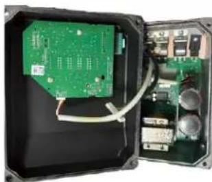
natural_image
Interior view of an electronic device showing a green circuit board and exposed wiring (no visible text or symbols)SWE - BESKRIVNING AV STEG
natural_image
Front view of a black industrial control panel with blue and red buttons (no visible text or symbols)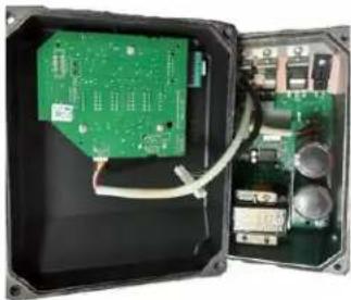
natural_image
Interior view of an electronic device showing a green circuit board and wiring, with no visible text or symbols.- EN - STEP3: Find the battery location.
Using a tool (small screwdriver or similar) introduce it into the hole indicated in the board for this purpose and carefully push the battery from its place.
FR - ÉTAPE 4 : RETIREZ LA BATTERIE
EN - Now, you can pick up the battery with your fingers and put it in the right place for the recycling.
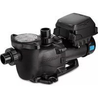
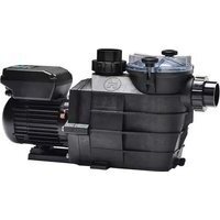
- HAYWARD®
- CE UK CA EAC i open book or trash can
- CE UK CA EAC i open book
- Bascule entre mode Manuel / mode Timer
- UTILISATION
- VARIABLE SPEED CENTRIFUGAL PUMP
- WARNING: Electrical Hazard. Failure to follow instructions can result in serious injury or death. FOR USE WITH SWIMMING POOLS
- GENERAL POINTS
- Necessary measures:
- INSTALLATION
- USING THE CONTROL PANEL
- INTRODUCTION
- Skimmer
- Timer mode
- Switching between Manual and Timer modes
- Manual mode Timer mode
- Connecting external digital inputs
- Examples of digital inputs
- N.B.
- Priming phase
- In Manual mode: selecting, setting and saving a custom speed
- Stopping / restarting the pump
- SETTINGS
- Setting the clock
- Setting the priming phase
- Setting the Skimmer function
- Restoring the settings
- Setting the Timer mode
- DISPLAYING CURRENT SETTINGS
- MAINTENANCE
- Wear parts estimated life
- WINTERING
- TROUBLESHOOTING
- A) The motor does not start
- B) The motor stops, check
- C) "OLOAD" appears on the display (overload or over-heating problem)
- D) The pump does not prime
- BOMBA CENTRÍFUGA DE VELOCIDAD VARIABLE
- USO
- Conexión
- BOMBA CENTRÍFUGA DE VELOCIDADE VARIÁVEL
- UTILIZAÇÃO
- ZENTRIFUGALPUMPE MIT VARIABLER GESCHWINDIGKEIT
- BEDIENUNG
- CENTRIFUGAALPOMP MET VARIABELE SNELHEID
- GEBRUIK
- Inschakelen
- POMPA CENTRIFUGA A VELOCITÀ VARIABILE
- ANVÄNDNING
- Aktiverad
- SENTRIFUGALPUMPE MED VARIABEL HASTIGHET
- Skifte mellom Manuell modus / Timer-modus
- CENTRIFUGEPUMPE MED VARIABEL HASTIGHED
- ADVARSEL: Elektrisk fare. Manglende overholdelse af instruktionerne kan resultere i alvorlig personskade eller død. TIL BRUG I SV∅MMEBASSER
- KESKIPAKOPUMPPU SÄÄDETTÄVÄLLÄ NOPEUDELLA
- KÄYTTÖ
- MAHDOLLISET VIAT JA RATKAISUT
- INCH LBS
- N m
- K-FLO VSTD SERIES
- RS II VSTD SERIES
- MAX FLO XL VSTD SERIES
- SUPERPUMP VSTD
- E-FLO VSTD SERIES
- CONDITIONS DE GARANTIE ET EXCLUSIONS POUR LES PAYS DE L'UNION EUROPÉENNE
- WARRANTY CONDITIONS AND EXCLUSIONS FOR EU COUNTRIES
- FR - INFORMATIONS ENVIRONNEMENTALES:
- SWE - MILJÖINFORMATION:
- FR - DESCRIPTION DES ÉTAPES
- SWE - BESKRIVNING AV STEG
- FR - ÉTAPE 4 : RETIREZ LA BATTERIE
Brand : HAYWARD
Model : KFlo VSTD
Category : Pump