
R3204 - Saw RIDGID - Free user manual and instructions
Find the device manual for free R3204 RIDGID in PDF.
| Marque | RIDGID |
| Modèle | R3204 |
| Type d'outil | Circular saw |
| Blade diameter | 165 mm (6-1/2 in) |
| Blade arbor | 16 mm (5/8 in) |
| Depth of cut at 90° | 54 mm (2-1/8 in) |
| Depth of cut at 45° | 41 mm (1-5/8 in) |
| Depth of cut at 50° | 38 mm (1-1/2 in) |
| Bevel capacity | 0° to 50° |
| No-load speed | 6,100 rpm |
| Power source | 120 V, 60 Hz, AC only, 12 A |
| Net weight | 3.6 kg (8 lb) |
| Construction | Double insulated (Class II) |
| Lower blade guard | Spring-return, manual retraction |
| Motor brushes | Externally accessible |
| Included in box | Saw, blade, hex key, owner's manual |
| Recommended accessories | Edge guide (part #202050004) |
| Warranty | 3-year limited |
| Maintenance | Regular cleaning, no lubrication needed, replace brushes if worn |
| Safety | Spindle lock, eye protection recommended, lower guard |
Frequently Asked Questions - R3204 RIDGID
User questions about R3204 RIDGID
0 question about this device. Answer the ones you know or ask your own.
Ask a new question about this device
Download the instructions for your Saw in PDF format for free! Find your manual R3204 - RIDGID and take your electronic device back in hand. On this page are published all the documents necessary for the use of your device. R3204 by RIDGID.
USER MANUAL R3204 RIDGID
OPERATOR'S MANUAL
6-1/2 in. CIRCULAR SAW
MANUEL D'UTILISATION
SCIE CIRCULAIRE DE 165 mm (6-1/2 po)
MANUAL DEL OPERADOR
SIERRA CIRCULAR DE 165 mm (6-1/2 pulg.)
R3204
To register your RIDGID
product, please visit:
http://register.RIDGID.com
Includes: Circular saw, blade, hex key, Operator's Manual
TABLE OF CONTENTS
\*\*\*\*\*\*\*\*\*\*\*\*\*\*\*\*\*\*\*\*\*\*\*\*\*\*\*\*\*\*\*\*\*\*\*\*\*\*\*\*\*\*\*\*\*\*\*\*\*\*\*\*\*\*\*\*\*\*\*\*\*\*\*\*\*\*\*\*\*\*\*\*\*\*\*\*\*\*\*\*\*\*\*\*\*\*\*\*
■ General Power Tool Safety
Warnings....2-3
■ Circular Saw Safety Rules......3-4
■ Symbols....5
■ Electrical....6
■ Features....7
■ Assembly....7-8
■ Operation....8-12
■ Adjustments ......12-13
■ Maintenance....13
■ Accessories....14
■ Illustrations ....15-17
■ Parts Ordering and Service....Back page

WARNING:
To reduce the risk of injury, the user must read and understand the operator's manual before using this product.
SAVE THIS MANUAL FOR FUTURE REFERENCE
Read all safety warnings and all instructions.
Failure to follow the warnings and instructions may result in electric shock, fire and/or serious injury.
Save all warnings and instructions for future reference. The term “power tool” in the warnings refers to your mains-operated (corded) power tool or battery-operated (cordless) power tool.
WORK AREA SAFETY
- Keep work area clean and well lit. Cluttered or dark areas invite accidents.
- Do not operate power tools in explosive atmospheres, such as in the presence of flammable liquids, gases or dust. Power tools create sparks which may ignite the dust or fumes.
- Keep children and bystanders away while operating a power tool. Distractions can cause you to lose control.
ELECTRICAL SAFETY
■ Power tool plugs must match the outlet. Never modify the plug in any way. Do not use any adapter plugs with earthed (grounded) power tools. Unmodified plugs and matching outlets will reduce risk of electric shock.
■ Avoid body contact with earthed or grounded surfaces such as pipes, radiators, ranges and refrigerators. There is an increased risk of electric shock if your body is earthed or grounded.
■ Do not expose power tools to rain or wet conditions. Water entering a power tool will increase the risk of electric shock.
- Do not abuse the cord. Never use the cord for carrying, pulling or unplugging the power tool. Keep cord away from heat, oil, sharp edges or moving parts. Damaged or entangled cords increase the risk of electric shock.
■ When operating a power tool outdoors, use an extension cord suitable for outdoor use. Use of a cord suitable for outdoor use reduces the risk of electric shock.
If operating a power tool in a damp location is unavoidable, use a ground fault circuit interrupter (GFCI) protected supply. Use of a GFCI reduces the risk of electric shock.
PERSONAL SAFETY
■ Stay alert, watch what you are doing and use common sense when operating a power tool. Do not use a power tool while you are tired or under the influence of drugs, alcohol or medication. A moment of inattention while operating power tools may result in serious personal injury.
■ Use personal protective equipment. Always wear eye protection. Protective equipment such as dust mask, non-skid safety shoes, hard hat, or hearing protection used for appropriate conditions will reduce personal injuries.
■ Prevent unintentional starting. Ensure the switch is in the off-position before connecting to power source and/or battery pack, picking up or carrying the tool. Carrying power tools with your finger on the switch or energising power tools that have the switch on invites accidents.
■ Remove any adjusting key or wrench before turning the power tool on. A wrench or a key left attached to a rotating part of the power tool may result in personal injury.
- Do not overreach. Keep proper footing and balance at all times. This enables better control of the power tool in unexpected situations.
■ Dress properly. Do not wear loose clothing or jewellery. Keep your hair, clothing and gloves away from moving parts. Loose clothes, jewellery or long hair can be caught in moving parts.
If devices are provided for the connection of dust extraction and collection facilities, ensure these are connected and properly used. Use of dust collection can reduce dust-related hazards.
- Do not wear loose clothing or jewelry. Contain long hair. Loose clothes, jewelry, or long hair can be drawn into air vents.
■ Do not use on a ladder or unstable support. Stable footing on a solid surface enables better control of the power tool in unexpected situations.
POWER TOOL USE AND CARE
- Do not force the power tool. Use the correct power tool for your application. The correct power tool will do the job better and safer at the rate for which it was designed.
■ Do not use the power tool if the switch does not turn it on and off. Any power tool that cannot be controlled with the switch is dangerous and must be repaired.
■ Disconnect the plug from the power source and/or the battery pack from the power tool before making any adjustments, changing accessories, or storing power tools. Such preventive safety measures reduce the risk of starting the power tool accidentally.
■ Store idle power tools out of the reach of children and do not allow persons unfamiliar with the power tool or these instructions to operate the power tool. Power tools are dangerous in the hands of untrained users. -
Maintain power tools. Check for misalignment or binding of moving parts, breakage of parts and any other condition that may affect the power tool's operation. If damaged, have the power tool repaired before use. Many accidents are caused by poorly maintained power tools.
-
Keep cutting tools sharp and clean. Properly maintained cutting tools with sharp cutting edges are less likely to bind and are easier to control.
■ Use the power tool, accessories and tool bits etc. in accordance with these instructions, taking into account the working conditions and the work to be performed. Use of the power tool for operations different from those intended could result in a hazardous situation.
SERVICE
■ Have your power tool serviced by a qualified repair person using only identical replacement parts. This will ensure that the safety of the power tool is maintained.
■ When servicing a power tool, use only identical replacement parts. Follow instructions in the Maintenance section of this manual. Use of unauthorized parts or failure to follow Maintenance instructions may create a risk of shock or injury.
CIRCULAR SAW SAFETY WARNINGS
CUTTING PROCEDURES

DANGER:
Keep hands away from cutting area and the blade. Keep your second hand on auxiliary handle, or motor housing. If both hands are holding the saw, they cannot be cut by the blade.
■ Do not reach underneath the workpiece. The guard can not protect you from the blade below the workpiece.
■ Adjust the cutting depth to the thickness of the workpiece. Less than a full tooth of the blade teeth should be visible below the workpiece.
■ Never hold piece being cut in your hands or across your leg. Secure the workpiece to a stable platform. It is important to support the work properly to minimize body exposure, blade binding, or loss of control.
- Hold the power tool by insulated gripping surfaces only, when performing an operation where the cutting tool may contact hidden wiring or its own cord. Contact with a “live” wire will also make exposed metal parts of the power tool “live” and could give the operator an electric shock.
■ When ripping, always use a rip fence or straight edge guide. This improves the accuracy of cut and reduces the chance of blade binding.
■ Always use blades with correct size and shape (diamond versus round) of arbour holes. Blades that do not match the mounting hardware of the saw will run eccentrically, causing loss of control.
■ Never use damaged or incorrect blade washers or bolt. The blade washers and bolt were specially designed for your saw, for optimum performance and safety of operation.
KICKBACK CAUSES AND RELATED WARNINGS
■ Kickback is a sudden reaction to a pinched, bound or misaligned saw blade, causing an uncontrolled saw to lift up and out of the workpiece toward the operator;
■ When the blade is pinched or bound tightly by the kerf closing down, the blade stalls and the motor reaction drives the unit rapidly back toward the operator;
If the blade becomes twisted or misaligned in the cut, the teeth at the back edge of the blade can dig into the top surface of the wood causing the blade to climb out of the kerf and jump back toward the operator.
Kickback is the result of saw misuse and/or incorrect operating procedures or conditions and can be avoided by taking proper precautions as given below:
- Maintain a firm grip with both hands on the saw and position your arms to resist kickback forces. Position your body to either side of the blade, but not in line with the blade. Kickback could cause the saw to jump backwards, but kickback forces can be controlled by the operator, if proper precautions are taken.
■ When blade is binding, or when interrupting a cut for any reason, release the trigger and hold the saw motionless in the material until the blade comes to a complete stop. Never attempt to remove the saw from the work or pull the saw backward while the blade is in motion or kickback may occur. Investigate and take corrective actions to eliminate the cause of blade binding.
■ When restarting a saw in the workpiece, centre the saw blade in the kerf and check that saw teeth are not engaged into the material. If saw blade is binding, it may walk up or kickback from the workpiece as the saw is restarted.
■ Support large panels to minimise the risk of blade pinching and kickback. Large panels tend to sag under their own weight. Supports must be placed under the panel on both sides, near the line of cut and near the edge of the panel.
■ Do not use dull or damaged blades. Unsharpened or improperly set blades produce narrow kerf causing excessive friction, blade binding and kickback.
■ Blade depth and bevel adjusting locking levers must be tight and secure before making cut. If blade adjustment shifts while cutting, it may cause binding and kickback.
■ Use extra caution when sawing into existing walls or other blind areas. The protruding blade may cut objects that can cause kickback.
LOWER GUARD FUNCTION
- Check lower guard for proper closing before each use. Do not operate the saw if lower guard does not move freely and close instantly. Never clamp or tie the lower guard into the open position. If saw is accidentally dropped, lower guard may be bent. Raise the lower guard with the retracting handle and make sure it moves freely and does not touch the blade or any other part, in all angles and depths of cut.
- Check the operation of the lower guard spring. If the guard and the spring are not operating properly, they must be serviced before use. Lower guard may operate sluggishly due to damaged parts, gummy deposits, or a build-up of debris.
■ Lower guard should be retracted manually only for special cuts such as “plunge cuts” and “compound cuts.” Raise lower guard by retracting handle and as soon as blade enters the material, the lower guard must be released. For all other sawing, the lower guard should operate automatically.
■ Always observe that the lower guard is covering the blade before placing saw down on bench or floor. An unprotected, coasting blade will cause the saw to walk backwards, cutting whatever is in its path. Be aware of the time it takes for the blade to stop after switch is released.
ADDITIONAL SAFETY WARNINGS
■ Use clamps or other practical way to secure and support the workpiece to a stable platform. Holding the work by hand or against your body is unstable and may lead to loss of control.
- Know your power tool. Read operator's manual carefully. Learn its applications and limitations, as well as the specific potential hazards related to this tool. Following this rule will reduce the risk of electric shock, fire, or serious injury.
■ Always wear eye protection with side shields marked to comply with ANSI Z87.1. Failure to do so could result in objects being thrown into your eyes, resulting in possible serious injury.
■ Protect your lungs. Wear a face or dust mask if the operation is dusty. Following this rule will reduce the risk of serious personal injury.
■ Protect your hearing. Wear hearing protection during extended periods of operation. Following this rule will reduce the risk of serious personal injury.
■ Inspect tool cords periodically and, if damaged, have repaired at your nearest authorized service center. Constantly stay aware of cord location. Following this rule will reduce the risk of electric shock or fire.
■ Check damaged parts. Before further use of the tool, a guard or other part that is damaged should be carefully checked to determine that it will operate properly and perform its intended function. Check for alignment of moving parts, binding of moving parts, breakage of parts, mounting, and any other conditions that may affect its operation. A guard or other part that is damaged should be properly repaired or replaced by an authorized service center. Following this rule will reduce the risk of shock, fire, or serious injury.
■ Make sure your extension cord is in good condition. When using an extension cord, be sure to use one heavy enough to carry the current your product will draw. A wire gauge size (A.W.G.) of at least 12 is recommended for an extension cord 50 feet or less in length. A cord exceeding 100 feet is not recommended. If in doubt, use the next heavier gauge. The smaller the gauge number, the heavier the cord. An undersized cord will cause a drop in line voltage resulting in loss of power and overheating.
■ Inspect for and remove all nails from lumber before using this tool. Following this rule will reduce the risk of serious personal injury.
If the power supply cord is damaged, it must be replaced only by the manufacturer or by an authorized service center to avoid risk.
■ Save these instructions. Refer to them frequently and use them to instruct others who may use this tool. If you loan someone this tool, loan them these instructions also.
| The following signal words and meanings are intended to explain the levels of risk associated with this product. | ||
| SYMBOL | SIGNAL | MEANING |
 | DANGER: | Indicates a hazardous situation, which, if not avoided, will result in death or serious injury. |
 | WARNING: | Indicates a hazardous situation, which, if not avoided, could result in death or serious injury. |
 | CAUTION: | Indicates a hazardous situation, that, if not avoided, may result in minor or moderate injury. |
| NOTICE: | (Without Safety Alert Symbol) Indicates information considered important, but not related to a potential injury (e.g. messages relating to property damage). | |
| Some of the following symbols may be used on this product. Please study them and learn their meaning. Proper interpretation of these symbols will allow you to operate the product better and safer. SYMBOL NAME DESIGNATION/EXPLANATION | ||
 | Safety Alert Indicates a potential | personal injury hazard. |
 | Read Operator's Manual | To reduce the risk of injury, user must read and understand operator's manual before using this product. |
  | Wear Eye Protection | Always wear eye protection with side shields marked to comply with ANSI Z87.1. |
 | Wet Conditions Alert Do not expose to rain or use in damp locations. | |
 | No Hands Symbol | Failure to keep your hands away from the blade will result in serious personal injury. |
| V Volts Voltage | ||
| A Amperes Current | ||
| Hz Hertz Frequency (cycles per second) | ||
| min Minutes Time | ||
| ~ | Alternating Current Type of current | |
| n0 | No Load Speed Rotational speed, at no load | |
| ☐ | Class II Tool Double-insulated construction | |
| .../min | Per Minute | Revolutions, strokes, surface speed, orbits etc., per minute |
DOUBLE INSULATION
Double insulation is a concept in safety in electric power tools, which eliminates the need for the usual three-wire grounded power cord. All exposed metal parts are isolated from the internal metal motor components with protecting insulation. Double insulated tools do not need to be grounded.

WARNING:
The double insulated system is intended to protect the user from shock resulting from a break in the tool's internal wiring. Observe all normal safety precautions to avoid electrical shock.
NOTE: Servicing of a tool with double insulation requires extreme care and knowledge of the system and should be performed only by a qualified service technician. For service, we suggest you return the tool to your nearest authorized service center for repair. Always use original factory replacement parts when servicing.
ELECTRICAL CONNECTION
This tool has a precision-built electric motor. It should be connected to a power supply that is 120 volts, 60 Hz, AC only (normal household current). Do not operate this tool on direct current (DC). A substantial voltage drop will cause a loss of power and the motor will overheat. If your tool does not operate when plugged into an outlet, double-check the power supply.
EXTENSION CORDS
When using a power tool at a considerable distance from a power source, be sure to use an extension cord that has the capacity to handle the current the tool will draw. An undersized cord will cause a drop in line voltage, resulting in overheating and loss of power. Use the chart to determine the minimum wire size required in an extension cord. Only round jacketed cords listed by Underwriter's Laboratories (UL) should be used.
When working outdoors with a tool, use an extension cord that is designed for outside use. This type of cord is designated with "W-A" OR "W" on the cord's jacket.
Before using any extension cord, inspect it for loose or exposed wires and cut or worn insulation.
**Ampere rating (on tool data plate)
0-2.0 2.1-3.4 3.5-5.0 5.1-7.0 7.1-12.0 12.1-16.0
Cord Length Wire Size (A.W.G.)
| 25' | 16 | 16 | 16 | 16 | 14 | 14 |
| 50' | 16 | 16 | 16 | 14 | 14 | 12 |
| 100' | 16 | 16 | 14 | 12 | 10 | — |
**Used on 12 gauge - 20 amp circuit.
NOTE: AWG = American Wire Gauge

WARNING:
Keep the extension cord clear of the working area. Position the cord so that it will not get caught on lumber, tools or other obstructions while you are working with a power tool. Failure to do so can result in serious personal injury.

WARNING:
Check extension cords before each use. If damaged replace immediately. Never use tool with a damaged cord since touching the damaged area could cause electrical shock resulting in serious injury.
PRODUCT SPECIFICATIONS
Blade Diameter....6-1/2 in.
Blade Arbor 5/8 in.
Cutting Depth at 90° .....2-1/8 in.
Cutting Depth at 45° .....1-5/8 in.
Cutting Depth at 50°....1-1/2 in.
No Load Speed 6,100 r/min. (RPM)
Input 120 V, 60 Hz, AC only, 12 Amps
Net Weight....8 lbs.
ASSEMBLY
UNPACKING
This product requires assembly.
- Carefully remove the tool and any accessories from the box. All items listed in the Includes section must be included at the time of purchase.

WARNING:
Do not use this product if any parts on the Includes List are already assembled to your product when you unpack it. Parts on this list are not assembled to the product by the manufacturer and require customer installation. Use of a product that may have been improperly assembled could result in serious personal injury.
■ If any parts are damaged or missing, please call 1-866-539-1710 for assistance.

WARNING:
If any parts are damaged or missing do not operate this product until the parts are replaced. Use of this product with damaged or missing parts could result in serious personal injury.

WARNING:
Do not attempt to modify this tool or create accessories not recommended for use with this tool. Any such alteration or modification is misuse and could result in a hazardous condition leading to possible serious personal injury.

WARNING:
Do not connect to power supply until assembly is complete. Failure to comply could result in accidental starting and possible serious personal injury.
ATTACHING THE BLADE
See Figure 1, page 15.

WARNING:
A 6-1/2 in. blade is the maximum blade capacity of the saw. Never use a blade that is too thick to allow outer blade washer to engage with the flat on the spindle. Larger blades will come in contact with the blade guards, while thicker blades will prevent blade screw from securing blade on spindle. Either of these situations could result in a serious accident.
■ Unplug the saw.
■ Remove the hex key from the storage area.
■ Depress the spindle lock button and remove the blade screw and outer blade washer ("D" washer).
NOTE: Turn the blade screw counterclockwise to remove.
NOTICE:
To prevent damage to the spindle or spindle lock, always allow motor to come to a complete stop before engaging spindle lock.
NOTE: Do not run the circular saw with spindle lock engaged.
■ Wipe a drop of oil onto the inner flange bushing and outer blade washer ("D" washer) where they contact blade.

WARNING:
If inner flange bushing has been removed, replace it before placing blade on spindle. Failure to do so will prevent blade from tightening properly and could result in serious personal injury.
- Retract the lower blade guard into the upper blade guard using the lower blade guard handle. Make sure the lower guard spring works properly, allowing the guard to move freely.
- Check to see that the saw teeth and arrow on the saw blade and the arrow on the lower guard are pointing in the same direction.
■ Fit the saw blade inside the lower blade guard and onto the spindle.
NOTE: The saw teeth point upward at the front of the saw as shown.
- Replace outer blade washer ("D" washer).
■ Depress the spindle lock button, then replace the blade screw. Tighten the blade screw securely by turning it clockwise.
■ Return the hex key to the storage area.
REMOVING THE BLADE
See Figure 2, page 15.
■ Unplug the saw.
■ Remove the hex key from the storage area.
■ Depress the spindle lock button, and remove the blade screw by turning it counterclockwise.
■ Remove outer blade washer ("D" washer).
■ Lift lower blade guard.
■ Remove blade.
OPERATION

DANGER:
Keep hands away from cutting area and the blade. Keep your second hand on auxiliary handle, or motor housing. If both hands are holding the saw, they cannot be cut by the blade.

WARNING:
Do not allow familiarity with tools to make you careless. Remember that a careless fraction of a second is sufficient to inflict serious injury.

WARNING:
Always wear eye protection with side shields marked to comply with ANSI Z87.1. Failure to do so could result in objects being thrown into your eyes resulting in possible serious injury.

WARNING:
Do not use any attachments or accessories not recommended by the manufacturer of this product. The use of attachments or accessories not recommended can result in serious personal injury.
APPLICATIONS
You may use this tool for the purpose listed below:
■ Cutting all types of wood products (lumber, plywood, paneling, composition board, and hard board)
■ Cross cutting/rip cutting wood products
■ Bevel cutting wood products
■ Pocket cutting wood products

WARNING:
Never use abrasive cut-off wheels of any kind with this saw. Use of non wood cutting blades can result in property damage or serious personal injury.
KICKBACK
See Figures 3 - 6, page 16.
Kickback occurs when the blade stalls rapidly and the saw is driven back towards you. Blade stalling is caused by any action which pinches the blade in the wood.

DANGER:
Release switch immediately if blade binds or saw stalls. Kickback could cause you to lose control of the saw. Loss of control may lead to serious personal injury.
To guard against kickback, avoid dangerous practices such as the following:
■ Setting blade depth incorrectly
■ Sawing into knots or nails in workpiece
■ Twisting the blade while making a cut
■ Making a cut with a dull, gummed up, or improperly set blade
■ Supporting the workpiece incorrectly
■ Forcing a cut
■ Cutting warped or wet lumber
■ Operating the tool incorrectly or misusing the tool
To lessen the chance of kickback, follow these safety practices:
- Keep the blade at the correct depth setting. Less than a full tooth of the blade teeth should be visible below the workpiece.
- Inspect the workpiece for knots or nails before cutting. Never saw into a knot or nail.
■ Make straight cuts. Always use a straight edge guide when rip cutting. This helps prevent twisting the blade.
■ Use clean, sharp, and properly set blades. Never make cuts with dull blades.
■ Support the workpiece properly before beginning a cut.
■ Use steady, even pressure when making a cut. Never force a cut.
■ Do not cut warped or wet lumber.
- Hold the saw firmly with both hands and keep your body in a balanced position so as to resist the forces if kickback should occur.

WARNING:
When using the saw, always stay alert and exercise control. Do not remove the saw from the workpiece while the blade is moving.
SAW BLADES
The best of saw blades will not cut efficiently if they are not kept clean, sharp, and properly set. Using a dull blade will place a heavy load on the saw and increase the danger of kickback. Keep extra blades on hand so that sharp blades are always available.
Gum and wood pitch hardened on blades will slow the saw down. Remove saw blade from the saw and use gum and pitch remover, hot water, or kerosene to remove these accumulations. DO NOT USE GASOLINE.
BLADE GUARD SYSTEM
See Figure 7, page 16.
The lower blade guard attached to the circular saw is there for your protection and safety. Do not alter it for any reason. If it becomes damaged, do not operate the saw until you have the guard repaired or replaced. Always leave guard in operating position when using the saw.

DANGER:
When sawing through work, lower blade guard does not cover blade on the underside of work. Since blade is exposed on underside of work, keep hands and fingers away from cutting area. Any part of your body coming in contact with moving blade will result in serious injury.

WARNING:
To avoid possible serious injury, never use saw when guard is not operating correctly. Check the guard for correct operation before each use. The guard is operating correctly when it moves freely, and instantly returns to the closed position. If you drop the saw, check the lower blade guard and bumper for damage at all depth settings before reuse.

WARNING:
Never tie the lower blade guard in a raised position. Leaving the blade exposed could lead to serious injury.
If at any time the lower blade guard does not snap closed, unplug the saw from the power supply. Exercise the lower guard by moving it rapidly back and forth from the full open position to the closed position several times. Normally this will restore the guard to its normal operating condition. If it does not correct a slow or sluggish closing lower guard, do not use the saw. Take it to an authorized factory service center for repair.
STARTING/STOPPING THE SAW
See Figure 8, page 16.
To start the saw: Depress the switch trigger.
Always let the blade reach full speed, then guide the saw into the workpiece.

WARNING:
The blade coming in contact with the workpiece before it reaches full speed could cause the saw to "kickback" toward you, resulting in serious injury.
To stop the saw: Release the switch trigger.
After you release the switch trigger, allow the blade to come to a complete stop. Do not remove the saw from the workpiece while the blade is moving.
INDEXABLE LEVERS
See Figure 9, page 16.
The lock levers on the saw consist of a repositionable lever and locking hex screw. The levers can be repositioned without moving the hex screw for the best tightening orientation.
To reposition the lever:
■ With the lever seated against the hex screw, rotate the lever clockwise to lock the hex screw as tightly as possible with the lever in the current position.
■ Pull the lever away from the saw to disengage it from the hex screw.
- Keep a steady pull on the lever, then rotate the lever as needed to the desired position on the hex screw.
■ Release the lever so that it snaps into place on the hex screw.
NOTE: The lever may rotate slightly after release as it properly seats on the hex screw.
ADJUSTING BLADE DEPTH
See Figure 10, page 16.
Always keep correct blade depth setting. Less than a full tooth of the blade teeth should be visible below the workpiece. More blade depth will increase the chance of kickback and cause the cut to be rough. For more depth of cut accuracy, a scale is located on the upper blade guard.
To adjust the blade depth:
■ Unplug the saw.
■ Rotate depth lock lever away from the base.
■ Determine the desired depth of cut.
■ Hold base flat against the workpiece and raise or lower saw until the indicator mark on the saw aligns with the desired depth on the scale.
■ Rotate depth lock lever toward the base to lock into position.
NOTE: If the lever contacts the base prior to the base being fully locked into position, refer to Indexable Levers earlier in this manual to adjust the lever counterclockwise on the hex screw.
NOTE: If the lever contacts the motor housing prior to the base being loosened, refer to Indexable Levers earlier in this manual to adjust the lever clockwise on the hex screw.
OPERATING THE SAW
See Figures 11 - 13, pages 16 and 17.
It is important to understand the correct method for operating the saw. Refer to the figures in this section to learn the correct and incorrect ways for handling the saw.

WARNING:
To make sawing easier and safer, always maintain proper control of the saw by holding the saw with two hands. Loss of control could cause an accident resulting in possible serious injury.

DANGER:
When lifting the saw from the workpiece, the blade is exposed on the underside of the saw until the lower blade guard closes. Make sure the lower blade guard is closed before setting the saw down.

WARNING:
Use clamps or other practical ways to secure and support the workpiece to a stable platform. Holding the work by hand or against your body is unstable and could lead to loss of control which could cause possible serious injury.
To make the best possible cut:
■ Hold the saw firmly with both hands.
■ Avoid placing your hand on the workpiece while making a cut.
■ Support the workpiece so that the cut (kerf) is always to your side.
■ Support the workpiece near the cut.
- Clamp the workpiece securely so that the workpiece will not move during the cut.
■ Always place the saw on the workpiece that is supported, not the “cut off” piece.
- Place the workpiece with the “good” side down.
■ Draw a guideline along the desired line of cut before beginning the cut.
- Keep the cord away from the cutting area. Always place the cord to prevent it from hanging up on the workpiece while making a cut.

WARNING:
If the cord hangs up on the workpiece during a cut, release the switch immediately and allow the blade to come to a complete stop. Unplug the saw and reposition the cord to prevent it from hanging up again.

WARNING:
Using a saw with a damaged cord could result in serious injury or death. If the cord has been damaged, have it replaced before using the saw again.
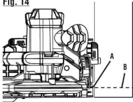
CROSS CUTTING/RIP CUTTING
See Figures 14 - 15, page 17.
When making a cross cut or rip cut, align the line of cut with the outer blade guide notch on the base.
Since blade thicknesses vary, always make a trial cut in scrap material along a guideline to determine how much, if any, you must offset the guideline to produce an accurate cut.
NOTE: The distance from the line of cut to the guideline is the amount you should offset the guide.
■ Secure the workpiece.
- Clamp a straight edge to the workpiece using C-clamps.
■ Saw along the straight edge to achieve a straight rip cut.
NOTE: Do not bind the blade in the cut.
USING OPTIONAL EDGE GUIDE
See Figure 16, page 17.
Use an edge guide, part no. 202050001, when making long or wide rip cuts with the saw.
To install the edge guide:
■ Unplug the saw.
■ Place edge guide through slots in base.
■ Adjust edge guide to the width needed.
■ Tighten edge guide lock knob securely.
When using an edge guide, position the face of the edge guide firmly against the edge of workpiece. This makes for a true cut without pinching the blade. The guiding edge of the workpiece must be straight for your cut to be straight. Use caution to prevent the blade from binding in the cut.
BEVEL CUTTING
See Figures 17 - 18, page 17.
To make the best possible cut:
■ Align the line of cut with the inner blade guide notch on the base when making 45° bevel cuts.
■ Make a trial cut in scrap material along a guideline to determine how much you should offset the guideline on the cutting material.
■ Adjust the angle of cut to any desired setting between zero and 50°. Positive stops are located at 0°, 15°, 22-1/2°, 30°, 45°, and 50°. Refer to To Adjust Bevel Setting.
To adjust the bevel setting:
■ Unplug the saw.
■ Rotate bevel lock lever counterclockwise until the motor housing moves freely.
■ Raise motor housing end of saw until you reach the desired angle setting on bevel scale.
■ Rotate the bevel lock lever clockwise until the motor housing is securely locked in place.
NOTE: If the lever contacts the base prior to the base being fully locked in position, refer to Indexable Levers earlier in this manual to adjust the lever counterclockwise on the hex screw.
NOTE: If the lever contacts the base prior to the base being loosened, refer to Indexable Levers earlier in this manual to adjust the lever clockwise on the hex screw.

WARNING:
Attempting a bevel cut without having the bevel lock knob securely tightened can result in serious injury.
To bevel cut:
■ Hold the saw firmly with both hands as shown.
■ Rest the front edge of the base on the workpiece.
■ Start the saw and let the blade reach full speed.
■ Guide the saw into the workpiece and make the cut.

WARNING:
The blade coming in contact with the workpiece before it reaches full speed could cause saw to "kickback" toward you resulting in serious injury.
■ Release the trigger and allow the blade to come to a complete stop.
■ Lift the saw from the workpiece.
POCKET CUTTING
See Figure 19, page 17.

WARNING:
Always adjust bevel setting to zero before making a pocket cut. Attempting a pocket cut at any other setting can result in loss of control of the saw possibly causing serious injury.
■ Adjust the bevel setting to 0° and lock the bevel adjustment lever.
■ Set the blade to the correct blade depth setting.
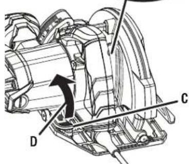
■ Swing the lower blade guard up using the lower blade guard handle.
NOTE: Always raise the lower blade guard with the handle to avoid serious injury.
- Hold the lower blade guard by the handle while keeping your hand on the front handle as shown.

WARNING:
Never extend your fingers while holding the lower blade guard handle. Extending your fingers may result in contact with the blade, causing serious injury.
■ Rest the front of the base flat against the workpiece with the rear of the handle raised so the blade does not touch the workpiece.

WARNING:
Always check to insure that your fingers are clear of the blade before depressing the switch trigger. Contact with the blade will cause serious injury.
■ Start the saw and let the blade reach full speed. Always let the blade reach full speed then slowly lower blade into the workpiece until base is flat against workpiece.
■ Guide the saw into the workpiece and make the cut.

WARNING:
Always cut in a forward direction when pocket cutting. Cutting in the reverse direction could cause the saw to climb up on the workpiece and back toward you.
■ Release the trigger and allow the blade to come to a complete stop.
■ Lift the saw from the workpiece.
■ Clear corners out with a hand saw or sabre saw.

WARNING:
Never tie the lower blade guard in a raised position. Leaving the blade exposed could lead to serious injury.
ADJUSTMENTS

WARNING:
Before performing any adjustment, make sure the tool is unplugged from the power supply and the switch is in the OFF (O) position. Failure to heed this warning could result in serious personal injury.
POSITIVE 0° BEVEL STOP
See Figure 20, page 17.
The saw has a positive 0° bevel stop that has been factory adjusted to assure 0° angle of the saw blade when making 0° cuts. However, misalignment can occur during shipping.
To check 0° bevel stop:
■ Unplug the saw.
■ Place saw in an upside down position on a workbench.
■ Move the lower blade guard out of the way so that the saw blade is exposed.
- Check the squareness of the saw blade to the base of the saw using a combination square.
To adjust 0° bevel stop:
■ Unplug the saw.
■ Rotate the bevel lock lever counterclockwise to release.
■ Turn T8 setscrew with T8 screwdriver (not provided) and adjust base until it is square with the saw blade.
■ Securely lock the bevel adjustment lever.
WARNING:
Attempting a bevel cut without having the bevel adjustment lever securely locked in place can result in serious injury.
MAINTENANCE

WARNING:
When servicing use only identical replacement parts. Use of any other parts may create a hazard or cause product damage.

WARNING:
Always wear eye protection with side shields marked to comply with ANSI Z87.1. Failure to do so could result in objects being thrown into your eyes resulting in possible serious injury.
GENERAL MAINTENANCE
Avoid using solvents when cleaning plastic parts. Most plastics are susceptible to damage from various types of commercial solvents and may be damaged by their use. Use clean cloths to remove dirt, dust, oil, grease, etc.

WARNING:
Do not at any time let brake fluids, gasoline, petroleum-based products, penetrating oils, etc., come in contact with plastic parts. Chemicals can damage, weaken or destroy plastic which may result in serious personal injury.
Electric tools used on fiberglass material, wallboard, spackling compounds, or plaster are subject to accelerated wear and possible premature failure because the fiberglass chips and grindings are highly abrasive to bearings, brushes, commutators, etc. Consequently, we do not recommend using this tool for extended work on these types of materials. However, if you do work with any of these materials, it is extremely important to clean the tool using compressed air.
LUBRICATION
All of the bearings in this tool are lubricated with a sufficient amount of high grade lubricant for the life of the unit under normal operating conditions. Therefore, no further lubrication is required.
POWER SUPPLY CORD REPLACEMENT
If replacement of the power supply cord is necessary, this has to be done by the manufacturer or his agent in order to avoid a safety hazard.
CHECKING/REPLACING EXTERNAL BRUSHES
See Figure 21, page 17.
NOTE: The saw is equipped with externally accessible brushes.
■ Unplug the saw.
WARNING:
Failure to unplug the tool could result in accidental starting causing possible serious injury.
NOTE: Brush caps (2) are located on each side of the motor housing.
■ Remove brush caps (2) using a screwdriver.
■ Remove brush assemblies (2).
- Check for wear. Replace both brush assemblies when either has less than 1/4 in. length of carbon remaining.
NOTE: Do not replace one side without replacing the other.
■ Reassemble using new brush assemblies. Make sure curvature of brush matches curvature of motor and that brush moves freely in brush tube.
■ Reassemble by reversing the steps listed above.
■ Tighten all brush caps securely. Do not over tighten.
To order these accessories, call 1-866-539-1710.
■ Edge Guide....202050001

WARNING:
Current attachments and accessories available for use with this tool are listed above. Do not use any attachments or accessories not recommended by the manufacturer of this tool. The use of attachments or accessories not recommended can result in serious personal injury.
CALIFORNIA PROPOSITION 65

WARNING:
This product and some dust created by power sanding, sawing, grinding, drilling, and other construction activities may contain chemicals, including lead, known to the State of California to cause cancer, birth defects, or other reproductive harm. Wash hands after handling.
Some examples of these chemicals are:
- lead from lead-based paints,
- crystalline silica from bricks and cement and other masonry products and,
• arsenic and chromium from chemically treated lumber.
Your risk from exposure to these chemicals varies, depending on how often you do this type of work. To reduce your exposure, work in a well-ventilated area and with approved safety equipment, such as dust masks that are specially designed to filter out microscopic particles.
ILLUSTRATIONS START ON PAGE 15 AFTER FRENCH AND SPANISH LANGUAGE SECTIONS.
This product has a 90-day satisfaction guarantee policy, as well as a three-year limited warranty. For warranty and policy details, please go to www.RIDGID.com or call (toll free) 1-866-539-1710.
RÈGLES DE SÉCURITÉ RELATIVES AUX OUTILS ELECTRIQUES

AVERTISSEMENT
0-2,0 2,1-3,4 3,5-5,0 5,1-7,0 7,1-12,0 12,1-16,0
| Longitud del cordón | Calibre conductores (A.W.G.) | ||||
| 25' | 16 | 16 | 16 | 16 | 14 |
| 50' | 16 | 16 | 16 | 14 | 14 |
| 100' | 16 | 16 | 14 | 12 | 10 |
NOTA: AWG = American Wire Gauge

ADVERTENCIA:
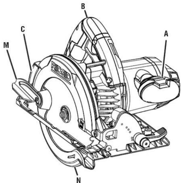
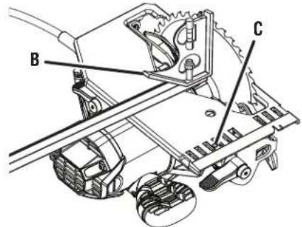
A - Front handle (poignée avant, mango delantero)
B - Handle (poignée, mango)
C - Dust chute (éjecteur de sciure, vertedero de aserrín)
D - Depth of cut scale (échelle de profondeur de coupe, escala de la profundidad de corte)
E - Switch trigger (commutateur, interruptor)
F - Hex key storage (compartiment de rangement de la clé hexagonale, lugar para guardar la llave hexagonal)
G - Spindle lock (verrouillage de broche, seguro del husillo)
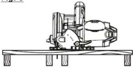
KICKBACK - BLADE SET TOO DEEP / REBOND - LAME TROP ENFONCÉE / CONTRAGOLPE - LA HOJA SE AJUSTÓ MUY PROFUNDA
Fig. 4
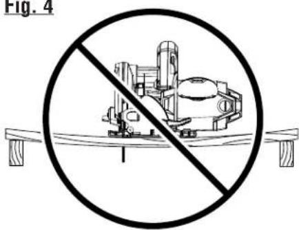
INCORRECT SUPPORT / SUPPORT INCORRECT / SOPORTE INCORRECTO
Fig. 5
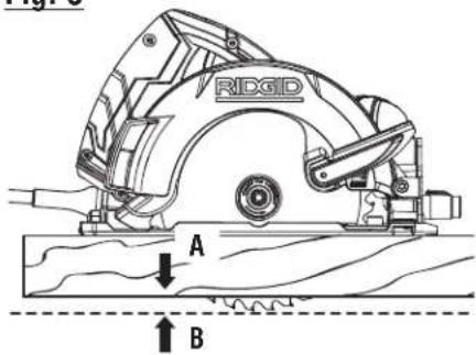
A - No more than 1/4 in. (pas plus de 6,35 mm [1/4 po], no mas de 6,35 mm [1/4 pulg.])
B - Correct blade depth setting = blade exposed 1/4 in. or less on underside of workpiece (réglage de profondeur de coupe correct = la lame dépasse de 6 mm [1/4 po] au maximum au-dessous de la pièce à travailler, ajuste correcto de la profundidad de la hoja = 6,35 mm [1/4 pulg.] de hoja expuesta o menos en el área inferior de la pieza de trabajo)
Fig. 6
CORRECT SUPPORT / SUPPORT CORRECT / SOPORTE CORRECTO
Fig. 7
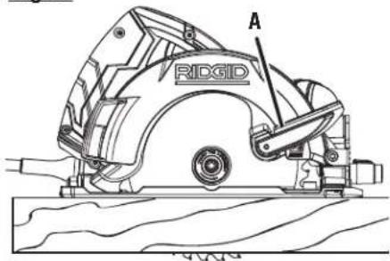
A - Switch trigger (commutateur, interruptor)
Fig. 9
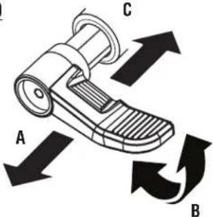
A - Pull the lever out to rotate (tirer le levier vers l'extérieur pour tourner, tire de la palanca hacia afuera para girar)
B - Rotate to the desired position (turner jusqu'à la position désirée, rote hasta la posición deseada)
C - Release the lever to lock (relâcher le levier pour bloquer, suelte la palanca para bloquear)
Fig. 10
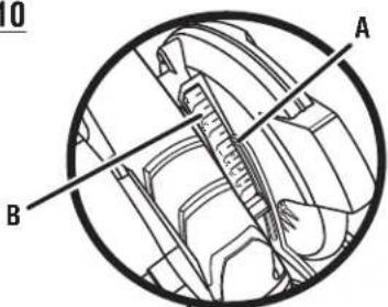
A - Depth indicator (indication de profondeur, indicador de profundidad)
B - Depth of cut scale (échelle de profondeur de coupe, escala de la profundidad de corte)
C - Depth lock lever (levier de verrouillage de profondeur, palanca de fijación de profundidad)
D - Lift lever to release (levier de levage pour relâcher, palanca de levantamiento para soltar)
Fig. 11
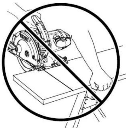
Fig. 12
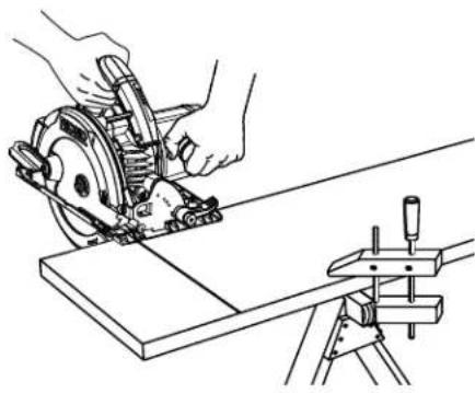
Fig. 13
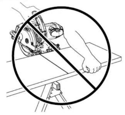
Fig. 14
A - C-clamps (serre-joint, prensa de mano)
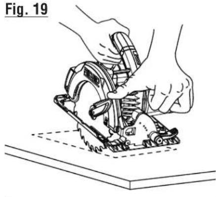
Fig. 20
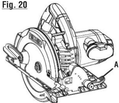
A - Bevel lock lever (levier de verrouillage de biseau, palanca de fijación del bisel)
B - Combination square (équerre combinée, escuadra de combinación)
A - Brush cap (couvercle de balai, tapa de la escobilla)
6-1/2 in. CIRCULAR SAW DOUBLE INSULATED
SCIE CIRCULAIRE DE 165 mm (6-1/2 po) DOUBLE ISOLATION
SIERRA CIRCULAR DE 165 mm (6-1/2 pulg.) DOBLE AISLAMIENTO
R3204
Customer Service Information:
For parts or service, do not return this product to the store. Contact your nearest RIDGID® authorized service center. Be sure to provide all relevant information when you call or visit. For the location of the authorized service center nearest you, please call 1-866-539-1710 or visit us online at www.RIDGID.com.
MODEL NO. ____ SERIAL NO. ____
RIDGID is a registered trademark of RIDGID, Inc., used under license.
990000385
5-15-17 (REV: 03)


- OPERATOR'S MANUAL
- 6-1/2 IN. CIRCULAR SAW
- MANUEL D'UTILISATION
- SCIE CIRCULAIRE DE 165 MM (6-1/2 PO)
- MANUAL DEL OPERADOR
- SIERRA CIRCULAR DE 165 MM (6-1/2 PULG.)
- TABLE OF CONTENTS
- WARNING
- SAVE THIS MANUAL FOR FUTURE REFERENCE
- WORK AREA SAFETY
- ELECTRICAL SAFETY
- PERSONAL SAFETY
- POWER TOOL USE AND CARE
- SERVICE
- CIRCULAR SAW SAFETY WARNINGS
- CUTTING PROCEDURES
- DANGER
- KICKBACK CAUSES AND RELATED WARNINGS
- LOWER GUARD FUNCTION
- ADDITIONAL SAFETY WARNINGS
- DOUBLE INSULATION
- ELECTRICAL CONNECTION
- EXTENSION CORDS
- PRODUCT SPECIFICATIONS
- ASSEMBLY
- UNPACKING
- ATTACHING THE BLADE
- NOTICE
- REMOVING THE BLADE
- OPERATION
- APPLICATIONS
- KICKBACK
- TO GUARD AGAINST KICKBACK, AVOID DANGEROUS PRACTICES SUCH AS THE FOLLOWING
- TO LESSEN THE CHANCE OF KICKBACK, FOLLOW THESE SAFETY PRACTICES
- SAW BLADES
- BLADE GUARD SYSTEM
- STARTING/STOPPING THE SAW
- INDEXABLE LEVERS
- TO REPOSITION THE LEVER
- ADJUSTING BLADE DEPTH
- TO ADJUST THE BLADE DEPTH
- OPERATING THE SAW
- TO MAKE THE BEST POSSIBLE CUT
- CROSS CUTTING/RIP CUTTING
- USING OPTIONAL EDGE GUIDE
- TO INSTALL THE EDGE GUIDE
- BEVEL CUTTING
- TO ADJUST THE BEVEL SETTING
- TO BEVEL CUT
- POCKET CUTTING
- ADJUSTMENTS
- POSITIVE 0° BEVEL STOP
- TO CHECK 0° BEVEL STOP
- TO ADJUST 0° BEVEL STOP
- MAINTENANCE
- GENERAL MAINTENANCE
- LUBRICATION
- POWER SUPPLY CORD REPLACEMENT
- CHECKING/REPLACING EXTERNAL BRUSHES
- CALIFORNIA PROPOSITION 65
- ILLUSTRATIONS START ON PAGE 15 AFTER FRENCH AND SPANISH LANGUAGE SECTIONS
- RÈGLES DE SÉCURITÉ RELATIVES AUX OUTILS ELECTRIQUES
- AVERTISSEMENT
- ADVERTENCIA
- 6-1/2 IN. CIRCULAR SAW DOUBLE INSULATED
- SCIE CIRCULAIRE DE 165 MM (6-1/2 PO) DOUBLE ISOLATION
- SIERRA CIRCULAR DE 165 MM (6-1/2 PULG.) DOBLE AISLAMIENTO
- CUSTOMER SERVICE INFORMATION
Brand : RIDGID
Model : R3204
Category : Saw