ChromaComfort - Fan NuTone - Free user manual and instructions
Find the device manual for free ChromaComfort NuTone in PDF.
User questions about ChromaComfort NuTone
0 question about this device. Answer the ones you know or ask your own.
Ask a new question about this device
Download the instructions for your Fan in PDF format for free! Find your manual ChromaComfort - NuTone and take your electronic device back in hand. On this page are published all the documents necessary for the use of your device. ChromaComfort by NuTone.
USER MANUAL ChromaComfort NuTone
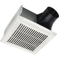
ChromaComfort™ Fan/Light Installation READ AND SAVE THESE INSTRUCTIONS
WARNING
TO REDUCE THE RISK OF FIRE, ELECTRIC SHOCK, OR INJURY TO PERSONS, OBSERVE THE FOLLOWING:
- Use this unit only in the manner intended by the manufacturer. If you have questions, contact the manufacturer at the address or telephone number listed in the warranty.
- Before servicing or cleaning unit, switch power off at service panel and lock the service disconnecting means to prevent power from being switched on accidentally. When the service disconnecting means cannot be locked, securely fasten a prominent warning device, such as a tag, to the service panel.
- Installation work and electrical wiring must be done by a qualified person(s) in accordance with all applicable codes and standards, including fire-rated construction codes and standards.
- Sufficient air is needed for proper combustion and exhausting of gases through the flue (chimney) of fuel burning equipment to prevent backdrafting. Follow the heating equipment manufacturer's guideline and safety standards such as those published by the National Fire Protection Association (NFPA), and the American Society for Heating, Refrigeration and Air Conditioning Engineers (ASHRAE), and the local code authorities.
- When cutting or drilling into wall or ceiling, do not damage electrical wiring and other hidden utilities.
- Ducted fans must always be vented to the outdoors.
- Acceptable for use over a tub or shower when connected to a GFCI (Ground Fault Circuit Interrupter) - protected branch circuit (ceiling installation only).
- This unit must be grounded.
CAUTION
- For general ventilating use only. Do not use to exhaust hazardous or explosive materials and vapors.
- This product can be installed in a wall if mounted 8-ft. or more above the floor.
- To avoid motor bearing damage and noisy and/or unbalanced impellers, keep drywall spray, construction dust, etc. off power unit.
- Please read specification label on product for further information and requirements.
For Warranty Statement, Service Parts, Technical Support, or to Register your product, please visit our website or call: In the United States - Broan.com 800-637-1453 or NuTone.com 888-336-6151. In Canada - Broan.ca or NuTone.ca 877-896-1119
CLEANING & MAINTENANCE
For quiet and efficient operation, long life, and attractive appearance - lower or remove grille and vacuum interior of unit with the dusting brush attachment.
The motor is permanently lubricated and never needs oiling. If the motor bearings are making excessive or unusual noises, replace the blower assembly (includes motor and impeller).
OPERATION
The Chroma Fan/Light must be operated using only the wall control included. See separate operating instructions. DO NOT operate the Chroma Fan/Light with any other switches or controls.
The Bluetooth ^® word mark and logos are registered trademarks owned by Bluetooth ^® SIG, Inc. and any use of such marks by Broan-NuTone LLC is under license. Other trademark and trade names are those of their respective owners.
NOTE: This equipment has been tested and found to comply with the limits for a Class B digital device, pursuant to Part 15 of the FCC Rules. These limits are designed to provide reasonable protection against harmful interference in a residential installation. This equipment generates, uses and can radiate radio frequency energy and, if not installed and used in accordance with the instructions, may cause harmful interference to radio communications. However, there is no guarantee that interference will not occur in a particular installation. If this equipment does cause harmful interference to radio or television reception, which can be determined by turning the equipment off and on, the user is encouraged to try to correct the interference by one or more of the following measures: - Reorient or relocate the receiving antenna.
- Increase the separation between the equipment and receiver.
- Connect the equipment into an outlet on a circuit different from that to which the receiver is connected.
- Consult the dealer or an experienced radio/TV technician for help.
This device complies with Part 15 of the FCC Rules and RSS-210 of Canada. Operation is subject to the following two conditions:
(1) This device may not cause interference, and (2) this device must accept any interference received, including interference that may cause undesired operation. FCC IDs: 2ADLL-RGB001 & 2ADLL-RGB002 IC IDs: 2143B-RGB001 & 2143B-RGB002
This Bluetooth ^® wireless technology enabled luminaire complies with FCC radiation exposure limits set forth for an uncontrolled environment. End users must follow the specific operating instructions for satisfying exposure compliance. This luminaire must not be co-located or operate in conjunction with any other antenna or transmitter.
Changes or modifications not expressly approved by the party responsible for compliance could void the user's authority to operate the equipment.
text_image
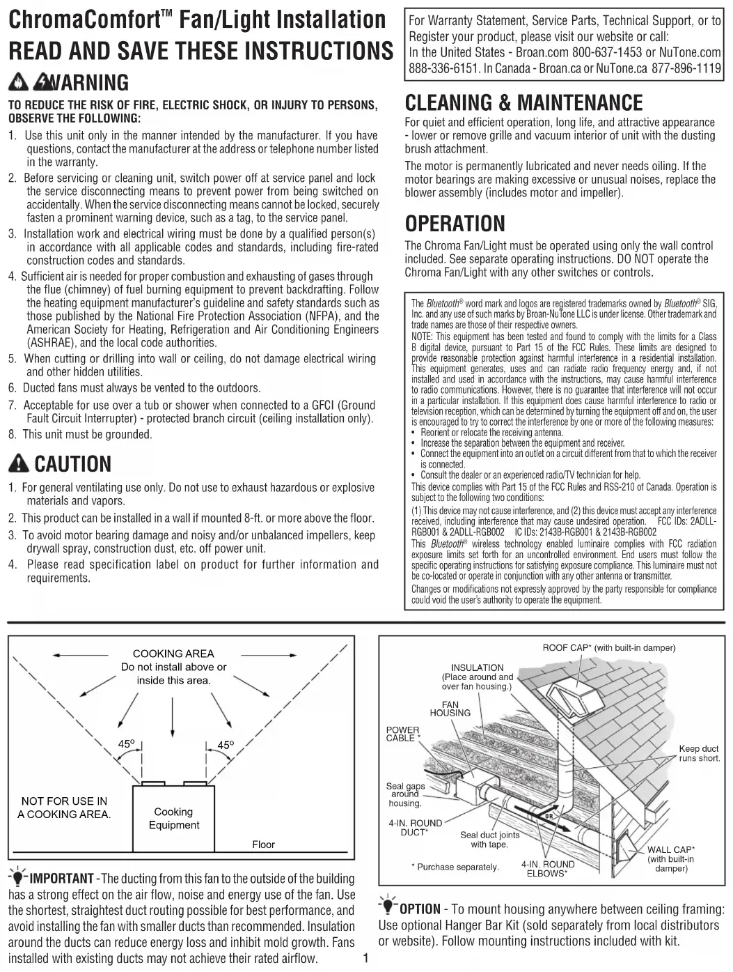
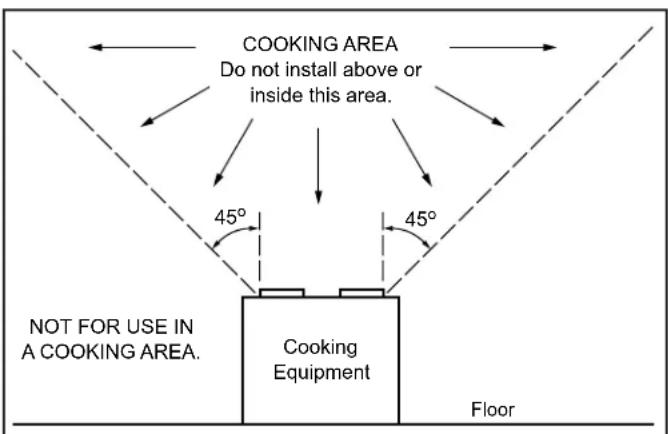
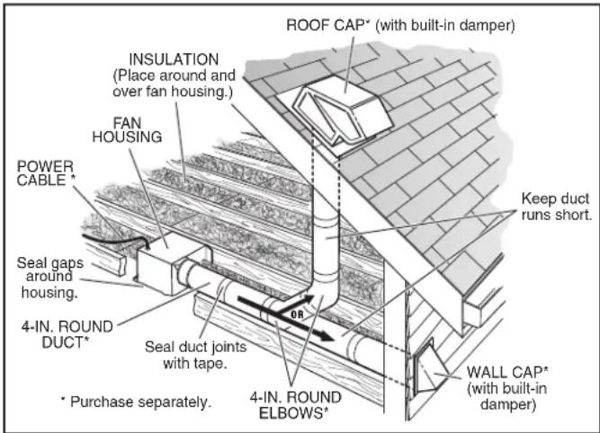
COOKING AREA Do not install above or inside this area. 45° 45° NOT FOR USE IN A COOKING AREA. Cooking Equipment FloorIMPORTANT - The ducting from this fan to the outside of the building has a strong effect on the air flow, noise and energy use of the fan. Use the shortest, straightest duct routing possible for best performance, and avoid installing the fan with smaller ducts than recommended. Insulation around the ducts can reduce energy loss and inhibit mold growth. Fans installed with existing ducts may not achieve their rated airflow.
text_image
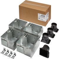
ROOF CAP* (with built-in damper) INSULATION (Place around and over fan housing.) FAN HOUSING POWER CABLE * Seal gaps around housing. 4-IN. ROUND DUCT* * Purchase separately. Seal duct joints with tape. 0R 4-IN. ROUND ELBOWS* Keep duct runs short. WALL CAP* (with built-in damper)OPTION - To mount housing anywhere between ceiling framing: Use optional Hanger Bar Kit (sold separately from local distributors or website). Follow mounting instructions included with kit.
ALL INSTALLATIONS
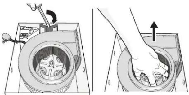
1 Remove all packing material, unplug and remove blower from fan housing.
natural_image
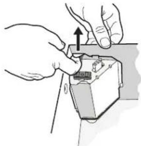
Two-step diagram showing a hand operating a device inside a circular housing, with no visible text or symbols.2 Remove wiring panel from fan housing.
natural_image
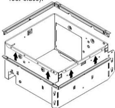
Illustration of hands installing or adjusting a device component with an upward arrow (no text or symbols)3 A pair of flanges may be attached to housing if desired or required.
Snap both flange pieces under rolled-over edge of housing (all four sides).
natural_image
Technical line drawing of a mechanical housing or enclosure with mounting brackets and internal components (no text or symbols)For Retrofit Installation - Skip to Page 3.
NEW INSTALLATION
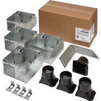
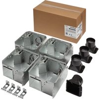
4 Attach damper/duct connector to fan housing.
Push connector through opening from inside of housing.
Engage tabs and secure with screw from parts bag.
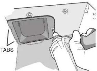
text_image
TABS5 Mount housing to ceiling structure.
Make sure bottom of housing will be flush with finished ceiling.
For proper location using 12 " ceiling material: Bend out housing tabs (on outside of housing) to fit against bottom of joist.
Secure housing through mounting ears with appropriate fasteners. If mounting housing to I-joist, use wood blocking as shown.
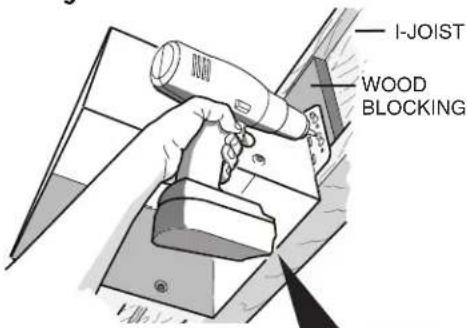
text_image
I-JOIST WOOD BLOCKING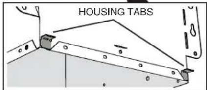
text_image
HOUSING TABS6 Connect 4-in. round duct.
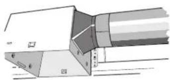
natural_image
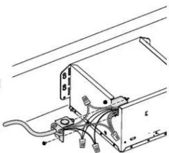
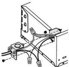
Technical line drawing of a mechanical component or assembly (no visible text or symbols)7 Connect wiring.
Connect power cable to wiring plate (from parts bag) using UL approved connector. Connect house wiring to fan wiring. Use screw (from parts bag) to secure wiring plate to fan housing. Re-install wiring panel and secure with screw from parts bag.
natural_image
Technical line drawing of a mechanical or electrical assembly with wires and components (no text or symbols)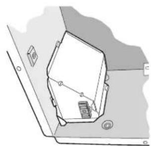
natural_image
Technical line drawing of a mechanical component or bracket with no visible text or symbols8 Finish ceiling. Then continue with Step 9.
RETROFIT INSTALLATION

Remove old fan and prepare ceiling.
Enlarge ceiling opening (if necessary) to 9 ^3/4 " parallel to joist) by 10 ^1/2 " (perpendicular to joist). (Some models have a cut-out template on side of carton.)
natural_image
Technical diagram of a mechanical assembly with a tool and component, no visible text or symbols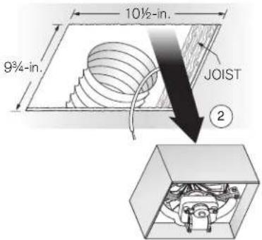
text_image
10½-in. 9¾-in. JOIST ②5
Fold mounting ears flat against housing.

natural_image
Hand inserting a component into a device housing (no text or symbols visible)Existing fan housings are typically attached to the structure:
• with screws, nails, or staples, which must be removed.
- with hangers or rails which are fastened to joists and must be removed along with housing.
A pry bar may be needed to remove the old housing.
Leave ductwork and wiring in place.

Connect wiring.
Connect power cable that will supply constant 120VAC to
unit. Attach wiring to wiring plate (from parts bag) using UL approved connector. Connect house wiring to fan wiring - black to black, white to white, and green to green or bare wire. Use screw (from parts bag) to secure wiring plate to fan housing. Re-install wiring panel and secure with screw from parts bag.
natural_image
Technical diagram of a computer monitor with cable and connector components (no text or labels)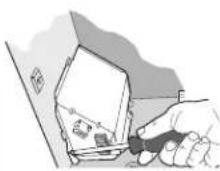
7
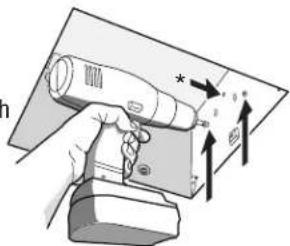
Mount fan to
ceiling structure.
Mount housing to ceiling structure with appropriate fasteners in locations shown.
natural_image
Illustration of a hand holding a handheld device with directional arrows indicating motion (no text or symbols)* Center hole is optional.

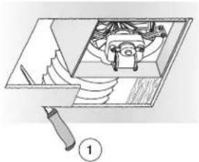
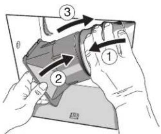
Connect 4-in. round duct.
① Pull existing ducting through housing discharge opening and ② tape ducting to duct connector.
③ Push connector/ducting back through opening. Engage tabs and ④ secure with screw from parts bag.
text_image
Diagram showing hands holding a device with numbered arrows indicating process steps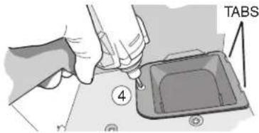
text_image
TABS ④Continue with Step 9.
ALL INSTALLATIONS

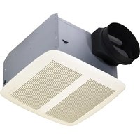
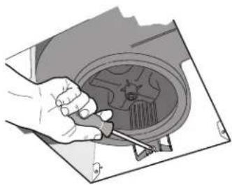
Install blower.
Re-install blower removed in Step 1. Secure blower with 2 screws from parts bag. Plug blower into black receptacle.
natural_image
Illustration of a hand using a screwdriver to adjust or install a mechanical component (no text or symbols visible)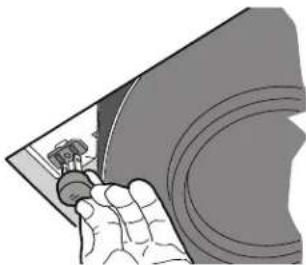
natural_image
Illustration of a hand holding a small object, possibly a tool or device, with no visible text or symbols.10
Install grille.
Connect 3 plugs from housing as shown. Squeeze grille springs and insert into slots in blower. Push grille up against ceiling.
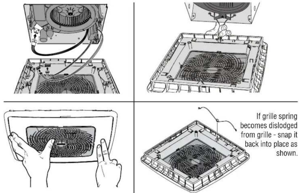
If grille spring becomes dislodged from grille - snap it back into place as shown.
11
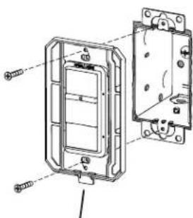
Install wall control.
Note: Location of wall control must be within 20-feet (not obstructed) of Chroma grille.
Use one of two methods to attach control:
(1) Mount control to new single-gang electrical box. (Recommended method)
(2) Mount control to wall with clearance hole in wall.
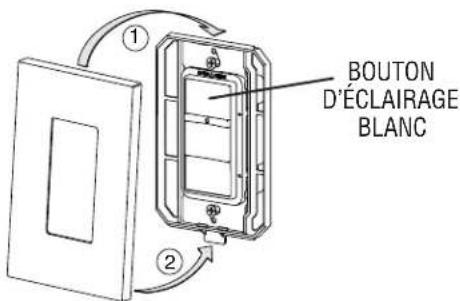
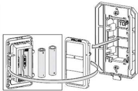
Remove control module, install 2-AAA batteries, and replace module.
Snap control cover in place. Note: Metallic cover plates are not recommended.
natural_image
Technical line drawing of a mechanical component with mounting holes and internal channels (no text or symbols)Note orientation of tab and buttons.
natural_image
Technical line drawing of an electrical enclosure with battery modules and wiring (no text or symbols)
text_image
WHITE LIGHT BUTTON12
Pair wall control.
Turn on power to fan. Within 3 minutes, hold white light button for 5+ seconds. White light button will flash to confirm pairing.
natural_image
Two technical diagrams showing a mechanical device inside a housing, with no visible text or symbols.natural_image
Illustration of hands installing or adjusting a device component with an upward arrow (no text or symbols)natural_image
Technical line drawing of a mechanical housing or enclosure with mounting brackets and internal components (no text or symbols)natural_image
Technical line drawing of a mechanical component or assembly (no visible text or symbols)natural_image
Technical line drawing of a mechanical or electrical component with wires and connectors (no text or symbols)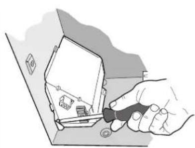
natural_image
Illustration of a hand using a screwdriver to insert or install a small electronic device (no text or symbols visible)natural_image
Hand inserting a component into a device housing (no text or symbols visible)text_image
Technical diagram showing electrical connections with labeled components and annotations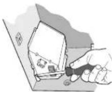
natural_image
Illustration of a hand holding a small object with a magnifying glass, next to a rectangular box (no text or symbols visible)7
text_image
Diagram showing a hand holding a handheld device with directional arrows and a label containing symbols like '1', '2', '3', '4', and an asterisk.text_image
Diagram showing hands holding a device with numbered arrows indicating process steps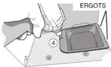
text_image
ERGOTS 4natural_image
Illustration of a hand using a tool to adjust or install a car wheel component (no text or symbols visible)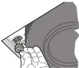
natural_image
Illustration of a hand holding a small object, possibly a tool or device, with no visible text or symbols.10
natural_image
Diagram of a mechanical device with internal components and wiring, no visible text or symbols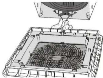
natural_image
Technical line drawing of a device with a fan inside a transparent casing (no text or symbols)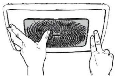
natural_image
Illustration of two hands interacting with a fingerprint on a tablet device (no text or symbols)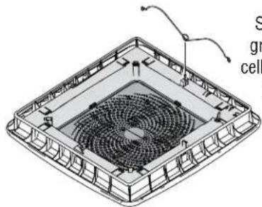
natural_image
Isometric view of a square grid structure with a central circular component and curved connection lines (no text or symbols)natural_image
Technical line drawing of an electrical switch panel with mounting holes and internal components (no text or symbols)natural_image
Technical line drawing of an electrical enclosure with battery modules and wiring (no text or symbols)