ExpertCenter PN52 - Desktop computer ASUS - Free user manual and instructions
Find the device manual for free ExpertCenter PN52 ASUS in PDF.

User questions about ExpertCenter PN52 ASUS
0 question about this device. Answer the ones you know or ask your own.
Ask a new question about this device
Download the instructions for your Desktop computer in PDF format for free! Find your manual ExpertCenter PN52 - ASUS and take your electronic device back in hand. On this page are published all the documents necessary for the use of your device. ExpertCenter PN52 by ASUS.
USER MANUAL ExpertCenter PN52 ASUS
No part of this manual, including the products and software described in it, may be reproduced, transmitted, transcribed, stored in a retrieval system, or translated into any language in any form or by any means, except documentation kept by the purchaser for backup purposes, without the express written permission of ASUSTeK COMPUTER INC. ("ASUS").
ASUS PROVIDES THIS MANUAL "AS IS" WITHOUT WARRANTY OF ANY KIND, EITHER EXPRESS OR IMPLIED, INCLUDING BUT NOT LIMITED TO THE IMPLIED WARRANTIES OR CONDITIONS OF MERCHANTABILITY OR FITNESS FOR A PARTICULAR PURPOSE. IN NO EVENT SHALL ASUS, ITS DIRECTORS, OFFICERS, EMPLOYEES OR AGENTS BE LIABLE FOR ANY INDIRECT, SPECIAL, INCIDENTAL, OR CONSEQUENTIAL DAMAGES (INCLUDING DAMAGES FOR LOSS OF PROFITS, LOSS OF BUSINESS, LOSS OF USE OR DATA, INTERRUPTION OF BUSINESS AND THE LIKE), EVEN IF ASUS HAS BEEN ADVISED OF THE POSSIBILITY OF SUCH DAMAGES ARISING FROM ANY DEFECT OR ERROR IN THIS MANUAL OR PRODUCT.
Products and corporate names appearing in this manual may or may not be registered trademarks or copyrights of their respective companies, and are used only for identification or explanation and to the owners' benefit, without intent to infringe.
SPECIFICATIONS AND INFORMATION CONTAINED IN THIS MANUAL ARE FURNISHED FOR INFORMATIONAL USE ONLY, AND ARE SUBJECT TO CHANGE AT ANY TIME WITHOUT NOTICE, AND SHOULD NOT BE CONSTRUED AS A COMMITMENT BY ASUS. ASUS ASSUMES NO RESPONSIBILITY OR LIABILITY FOR ANY ERRORS OR INACCURACIES THAT MAY APPEAR IN THIS MANUAL, INCLUDING THE PRODUCTS AND SOFTWARE DESCRIBED IN IT.
Copyright © 2022 ASUSTeK COMPUTER INC. All Rights Reserved.
LIMITATION OF LIABILITY
Circumstances may arise where because of a default on ASUS' part or other liability, you are entitled to recover damages from ASUS. In each such instance, regardless of the basis on which you are entitled to claim damages from ASUS, ASUS is liable for no more than damages for bodily injury (including death) and damage to real property and tangible personal property; or any other actual and direct damages resulted from omission or failure of performing legal duties under this Warranty Statement, up to the listed contract price of each product.
ASUS will only be responsible for or indemnify you for loss, damages or claims based in contract, tort or infringement under this Warranty Statement.
This limit also applies to ASUS' suppliers and its reseller. It is the maximum for which ASUS, its suppliers, and your reseller are collectively responsible.
UNDER NO CIRCUMSTANCES IS ASUS LIABLE FOR ANY OF THE FOLLOWING: (1) THIRD-PARTY CLAIMS AGAINST YOU FOR DAMAGES; (2) LOSS OF, OR DAMAGE TO, YOUR RECORDS OR DATA; OR (3) SPECIAL, INCIDENTAL, OR INDIRECT DAMAGES OR FOR ANY ECONOMIC CONSEQUENTIAL DAMAGES (INCLUDING LOST PROFITS OR SAVINGS), EVEN IF ASUS, ITS SUPPLIERS OR YOUR RESELLER IS INFORMED OF THEIR POSSIBILITY.
SERVICE AND SUPPORT
Visit our multi-language web site at https://www.asus.com/support/
Contents
About this manual....5
Conventions used in this manual....6
Package contents ....7
Getting to know your Mini PC
Features....10
Front view....10
Rear view....14
Using your Mini PC
Getting started 20
Connect the AC power adapter to your Mini PC....20
Connect a display panel to your Mini PC....22
Connect the USB cable from keyboard or mouse....25
Turn on your Mini PC 26
Turning off your Mini PC 27
Putting your Mini PC to sleep....27
Entering BIOS Setup 27
Load default BIOS settings....28
Upgrading your Mini PC
Removing the bottom cover 31
Replacing the bottom cover....33
Installing memory modules....35
Installing a 2.5" HDD or SSD....36
Installing an M.2 SSD....38
Installing a wireless card....41
Contents
TPM
About the TPM....44
Appendix
Safety information....46
Setting up your system....47
Care during use....47
Safety Precautions 48
Regulatory notices 49
Service and Support....56
About this manual
This manual provides information about the hardware and software features of your Mini PC, organized through the following chapters:
Chapter 1: Getting to know your Mini PC
This chapter details the hardware components of your Mini PC.
Chapter 2: Using your Mini PC
This chapter provides you with information on using your Mini PC.
Chapter 3: Upgrading your Mini PC
This chapter provides you with information on how to upgrade the memory modules, wireless modules, and hard disk drive / solid state drive of your Mini PC.
Chapter 4: TPM
This chapter provides you with information on the TPM options.
Appendix
This section includes notices and safety statements for your Mini PC.
Conventions used in this manual
To highlight key information in this manual, some text are presented as follows:
IMPORTANT! This message contains vital information that must be followed to complete a task.
NOTE: This message contains additional information and tips that can help complete tasks.
WARNING! This message contains important information that must be followed to keep you safe while performing certain tasks and prevent damage to your Mini PC's data and components.
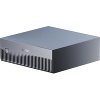
Package contents
Your Mini PC package contains the following items:
text_image
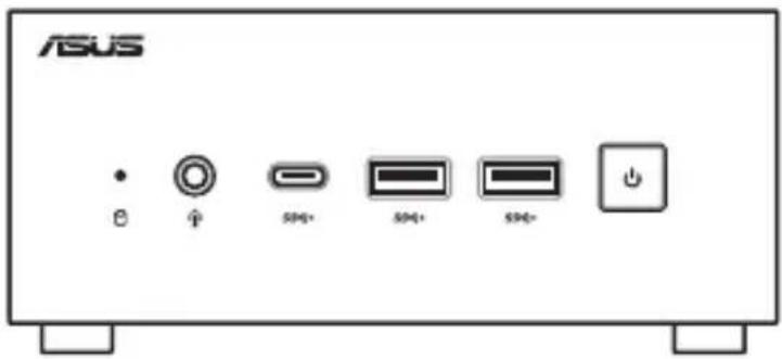
ASUS B ↑ S40+ S40+ S40+ 功ASUS Mini PC PN Series
natural_image
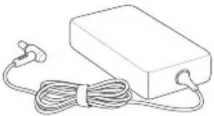
Line drawing of a rectangular electronic device with coiled cable and ear connectors (no text or symbols)
natural_image
Line drawing of a straight cord with multiple connectors (no text or symbols)AC power adapter* Power cord*
- *The bundled power adapter may vary by model and territory.
- Some bundled accessories may vary with different models. For details on these accessories, refer to their respective user manuals.
- The device illustration is for reference only. Actual product specifications may vary depending on model.
- If the device or its components fail or malfunction during normal and proper use within the warranty period, bring the warranty card to the ASUS Service Center for replacement of the defective components.
1
Getting to know your Mini PC
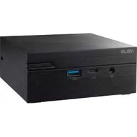
Features
Front view
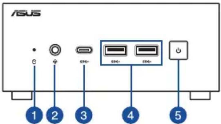
text_image
ASUS 1 2 3 4 51
Drive activity indicator
This indicator lights up when your Mini PC is accessing the internal storage drive.
2
Headphone/Headset/Microphone jack (optional)
This port allows you to connect amplified speakers or headphones. You can also use this port to connect your headset or an external microphone.
3
USB 3.2 Gen 1 Type-C® port
This USB 3.2 Gen 1 Type-C® port provides the following:
- Transfer rate of up to 5 Gbit/s for USB 3.2 Gen 1 devices.
- Backward compatible to USB 2.0.
• USB power delivery with a maximum of 5V / 3A output.


USB 3.2 Gen 1 port
The USB 3.2 Gen 1 (Universal Serial Bus) port provides a transfer rate up to 5 Gbit/s.


Power button
The power button allows you to turn the Mini PC on or off. You can use the power button to put your Mini PC to sleep mode or press it for four (4) seconds to force shutdown your Mini PC.
Left view
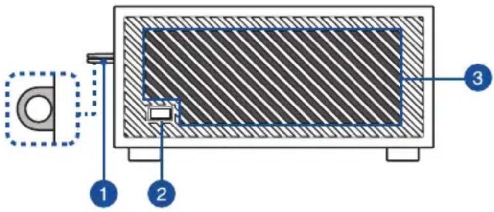
text_image
Technical diagram of a mechanical device with labeled components 1, 2, and 31
Padlock ring
This ring allows you to attach a standard padlock to prevent unauthorized disassembly of your Mini PC.
NOTE: The padlock is purchased separately.
2
Kensington security slot
The Kensington security slot allows you to secure your Mini PC using Kensington® security products.
3
Air vents (intake vent)
The air vents allow cooler air to enter your Mini PC chassis.
IMPORTANT: For an optimum heat dissipation and air ventilation, ensure that the air vents are free from obstructions.
Right view
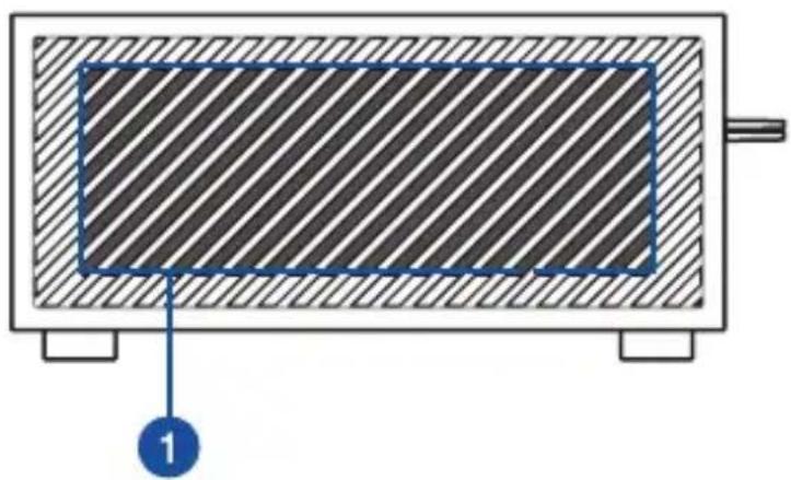
natural_image
Cross-sectional diagram of a mechanical component with hatched fill and labeled component 1 (no text or symbols beyond labels)1
Air vents (intake vent)
The air vents allow cooler air to enter your Mini PC chassis.
IMPORTANT: For an optimum heat dissipation and air ventilation, ensure that the air vents are free from obstructions.
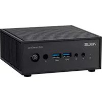
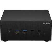
Rear view
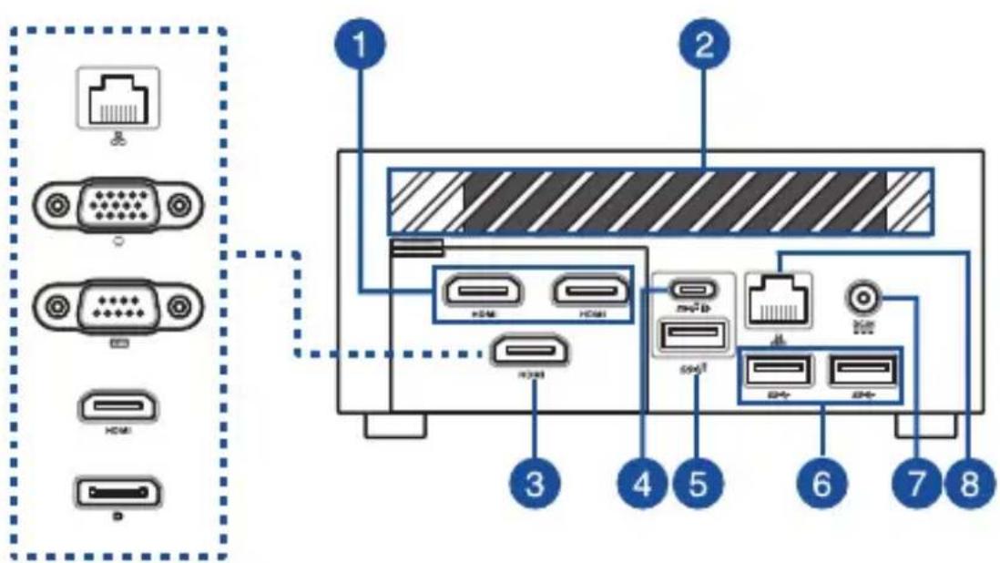
text_image
Diagram of a computer interface showing labeled ports and connectors, including VGA, HDMI, and Ethernet ports with numbered annotations.
HDMI
HDMI™ port
The HDMI™ (High Definition Multimedia Interface) port supports a Full-HD device, such as an LCD TV or monitor, to allow viewing on a larger external display.
NOTES:
The left HDMI port supports CEC (Consumer Electronics Control). Connect any CEC compatible device that you want to control with a remote control to this port, and make sure that the device's HDMI-CEC is enabled.
When using only this port as a display output source, this port will support a resolution of up to 4096 x 2304 @60Hz. The resolution may also be affected by the cabling and output device.
2
Air vents (exhaust vent)
The air vents allow your Mini PC chassis to expel hot air out.
IMPORTANT: For an optimum heat dissipation and air ventilation, ensure that the air vents are free from obstructions.
3
Configurable port
This port varies between models and consists of the following port options:
NOTE: This port may vary depending on model.

LAN port
The 8-pin RJ-45 LAN port supports a standard Ethernet cable for 10/100/1000/2500Mbps connection to a local network.

VGA port
This port allows you to connect your Mini PC to an external display.
NOTE: When using only this port as a display output source, this port will support a resolution of up to 1920 x 1200 @60Hz. The resolution may also be affected by the cabling and output device.

Serial (COM) connector
The 9-pin serial (COM) connector allows you to connect devices that have serial ports, such as mouse, modem, and printers.
HDMI
HDMI™ port
The HDMI™ (High Definition Multimedia Interface) port supports a Full-HD device such as an LCD TV or monitor to allow viewing on a larger external display.
NOTE: When using only this port as a display output source, this port will support a resolution of up to 4096 x 2304 @60Hz. The resolution may also be affected by the cabling and output device.

DisplayPort
This port allows you to connect your Mini PC to an external display.
NOTE: When using only this port as a display output source, this port will support a resolution of up to 5120 x 2880 @120Hz. The resolution may also be affected by the cabling and output device.


USB 3.2 Gen 2 Type-C® / DisplayPort / Power (DC) input combo port
This USB Type-C® (Universal Serial Bus) port provides the following:
- Transfer rate of up to 10 Gbit/s.
- Support for DisplayPort 1.4. Use a USB Type-C® adapter to connect your Mini PC to an external display.
• USB power delivery with a maximum of 5V / 3A output. - Support for 20V / 4.5-5.0A PD (Power Delivery) input when connected to an external device that is PD compliant.
CAUTION!
- DO NOT connect your Mini PC to a device which supports less than 20V / 4.5A PD when using the USB 3.2 Gen 2 Type-C® port as a power (DC) input port, doing so may cause problems when powering on your Mini PC.
- When using the USB 3.2 Gen 2 Type-C® port as a power (DC) input port, ensure to remove the cable from the Power input port.
- Ensure to power off your device when switching between the USB 3.2 Gen 2 Type-C® port and Power input port.
NOTES:
- Thepower (DC) input feature is only available on selected models.
- When using only this port as a display output source, this port will support a resolution of up to 5120 x 2880 @120Hz. The resolution may also be affected by the cabling and output device.


USB 3.2 Gen 2 port
The USB 3.2 Gen 2 (Universal Serial Bus) port provides a transfer rate up to 10 Gbit/s.


USB 3.2 Gen 1 port
The USB 3.2 Gen 1 (Universal Serial Bus) port provides a transfer rate up to 5 Gbit/s.


Power input
The supplied power adapter converts AC power to DC power for use with this jack. Power supplied through this jack supplies power to the Mini PC. To prevent damage to the Mini PC, always use the supplied power adapter.
WARNING! The power adapter may become warm to hot when in use. Do not cover the adapter and keep it away from your body.
NOTE: Please refer to the following information on the power adapter:
120W Power adapter: +20 V DC =6A, 120 W


LAN port
The 8-pin RJ-45 LAN port supports a standard Ethernet cable for 10/100/1000/2500 Mbps connection to a local network.
Using your Mini PC
2
Getting started
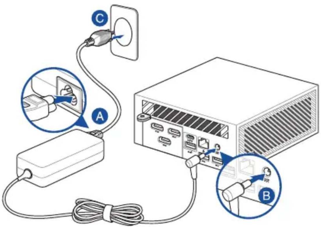
Connect the AC power adapter to your Mini PC
To connect the AC power adapter to your Mini PC:
A. Connect the power cord to the AC power adapter.
B. Connect the DC power connector into your Mini PC's power (DC) input.
C. Plug the AC power adapter into a 100V\~240V power source.
NOTE: The power adapter may vary in appearance, depending on models and your region.
text_image
Diagram showing cable connection to a computer with labeled components A, B, and C, including a close-up of cable routing.NOTE:
Please refer to the following for more information on the adapter:
120 W Power adapter
- Input voltage: 100-240 Vac
- Input frequency: 50-60 Hz
• Rating output current: 6 A (120 W)
• Rating output voltage: 20 V
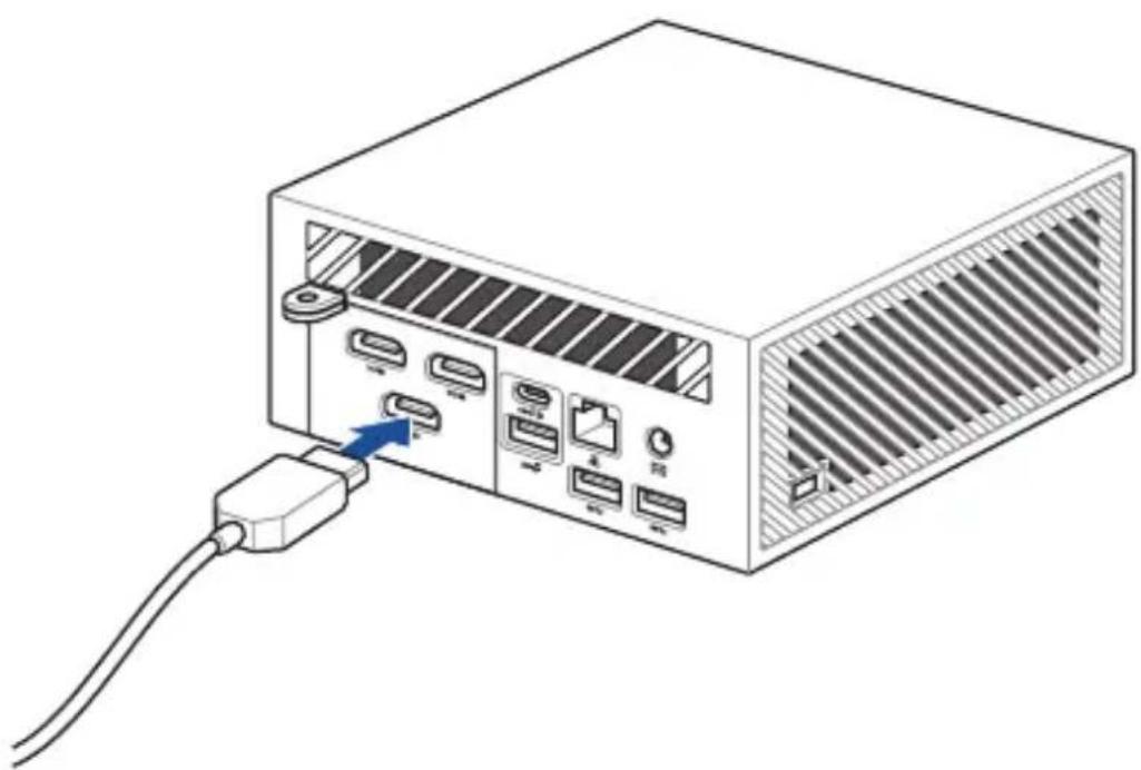
Connect a display panel to your Mini PC
You can connect a display panel or projector to your Mini PC that has the following port:
- HDMI™ port
- VGA port
- DisplayPort
- USB Type-C®/DisplayPort/Power (DC) input combo port
NOTE: These ports may vary depending on the model.
To connect a display panel to your Mini PC:
Connect one end of an HDMI™, VGA, or DisplayPort cable to an external display, and the other end of the cable to your Mini PC's HDMI™ port, VGA port, or DisplayPort.
Connect display via HDMI™ port
natural_image
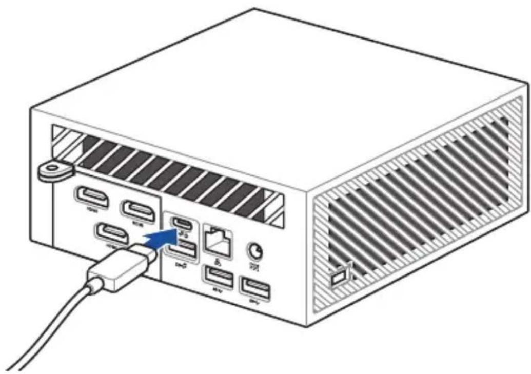
Illustration of a computer drive with ports and an external cable, showing no text or symbols.Connect display via DisplayPort

natural_image
Illustration of a computer drive with ports and an external cable, no text or symbols presentConnect display via VGA port

natural_image
Diagram of a computer drive showing ports, connectors, and cable (no text or labels)Connect display via USB Type-C®/DisplayPort/Power (DC) input combo port
natural_image
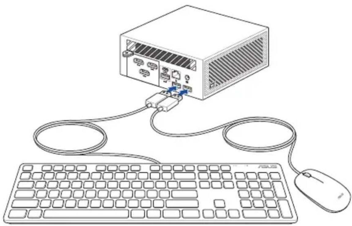
Illustration of a computer power drive showing port labels and connections (no text or symbols present)Connect the USB cable from keyboard or mouse
You can connect generally any USB keyboard and mouse to your Mini PC. You can also connect a USB dongle for a wireless keyboard and mouse set.
To connect a keyboard and mouse to your Mini PC:
Connect the USB cable from your keyboard and mouse to any of the USB ports of your Mini PC.
NOTE: The keyboard varies with country and/or region.
natural_image
Line drawing of a computer setup with a server, keyboard, and mouse (no text or symbols)Turn on your Mini PC
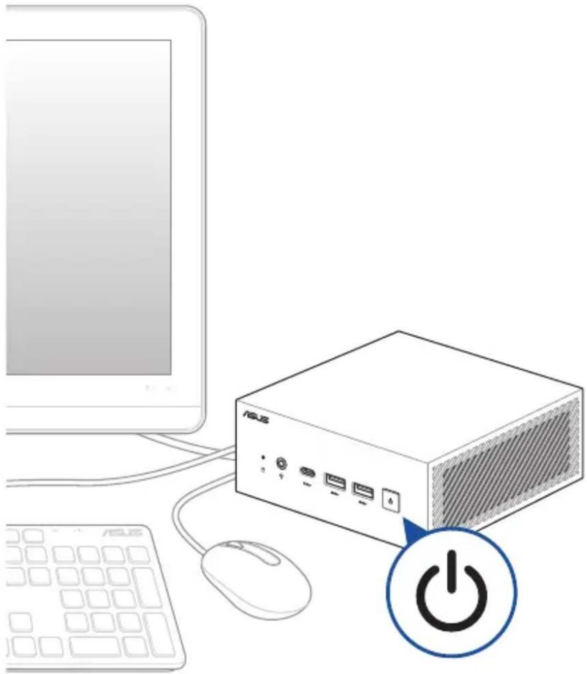
Press the power button to turn on your Mini PC.
natural_image
Illustration of a computer setup with a power switch, mouse, keyboard, and monitor (no text or symbols)Turning off your Mini PC
If your Mini PC is unresponsive, press and hold the power button for at least four (4) seconds until your Mini PC turns off.
Putting your Mini PC to sleep
To set your Mini PC to enter Sleep mode by pressing the Power button once, search for Control Panel in the Windows Search Box, then navigate to Hardware and Sound > Power Options > Choose what the power button does, and set When I press the power button to Sleep.
Entering BIOS Setup
BIOS (Basic Input and Output System) stores system hardware settings that are needed for system startup on the Mini PC.
Under normal circumstances, the default BIOS settings apply to most conditions to ensure optimal performance. Do not change the default BIOS settings except in the following circumstances:
- An error message appears on the screen during the system bootup and requests you to run BIOS Setup.
- You have installed a new system component that requires further BIOS settings or update.
WARNING! Inappropriate BIOS settings may result in instability or boot failure. We strongly recommend that you change the BIOS settings only with the help of a trained service personnel.
Load default BIOS settings
To load the default values for each of the parameters in your BIOS:
- Enter the BIOS by pressing
or from the POST screen.
NOTE: POST (Power-On Self Test) is a series of software controlled diagnostic tests that run when you turn on your Mini PC.
- Navigate to the Exit menu.
- Select the Load Optimized Defaults option or press
. - Select OK to load the default BIOS values.
3
Upgrading your Mini PC
IMPORTANT!
- It is recommended that you install or upgrade the memory modules, wireless card, and solid state drive (SSD) under professional supervision. Visit an ASUS service center for further assistance.
- Ensure that your hands are dry before proceeding with the rest of the installation process. Before installing any of the features in this guide, use a grounded wrist strap or touch a safely grounded object or metal object to avoid damaging them due to static electricity.
NOTE: The illustrations in this section are for reference only. The slots may vary depending on model.
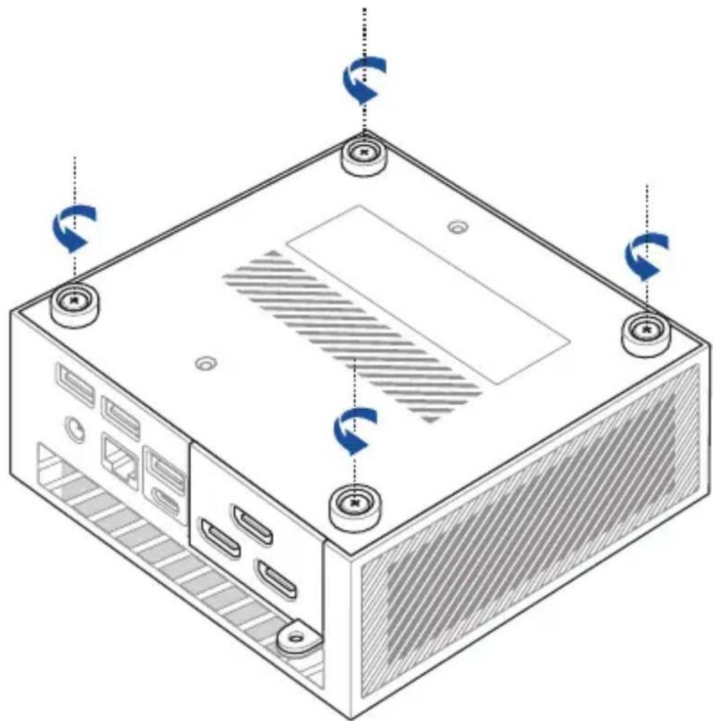
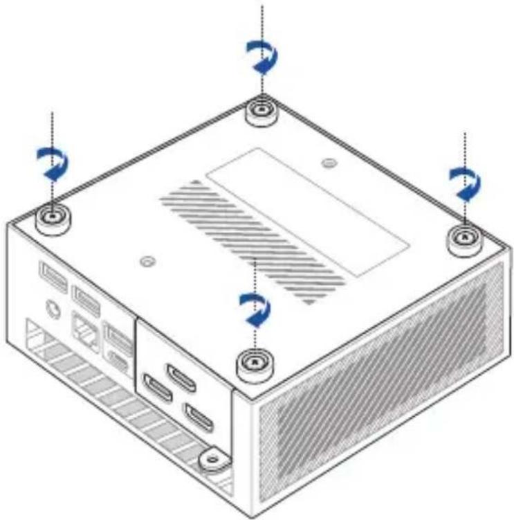
Removing the bottom cover
- Turn off your Mini PC then disconnect all cables and peripherals.
- Place the Mini PC on a flat stable surface with its top side facing down.
- Completely loosen the four (4) screws from the bottom cover.
natural_image
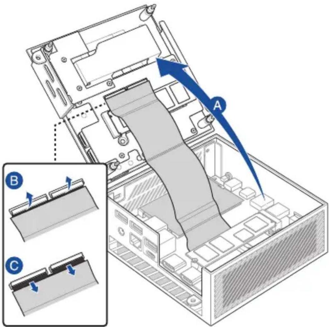
Isometric diagram of a computer tower with visible ventilation slots and scroll arrows indicating rotation (no text or symbols)- Gently lift the bottom cover in the direction shown in the illustration (A), then flip the connector flaps open (B) and remove the cable (C).
text_image
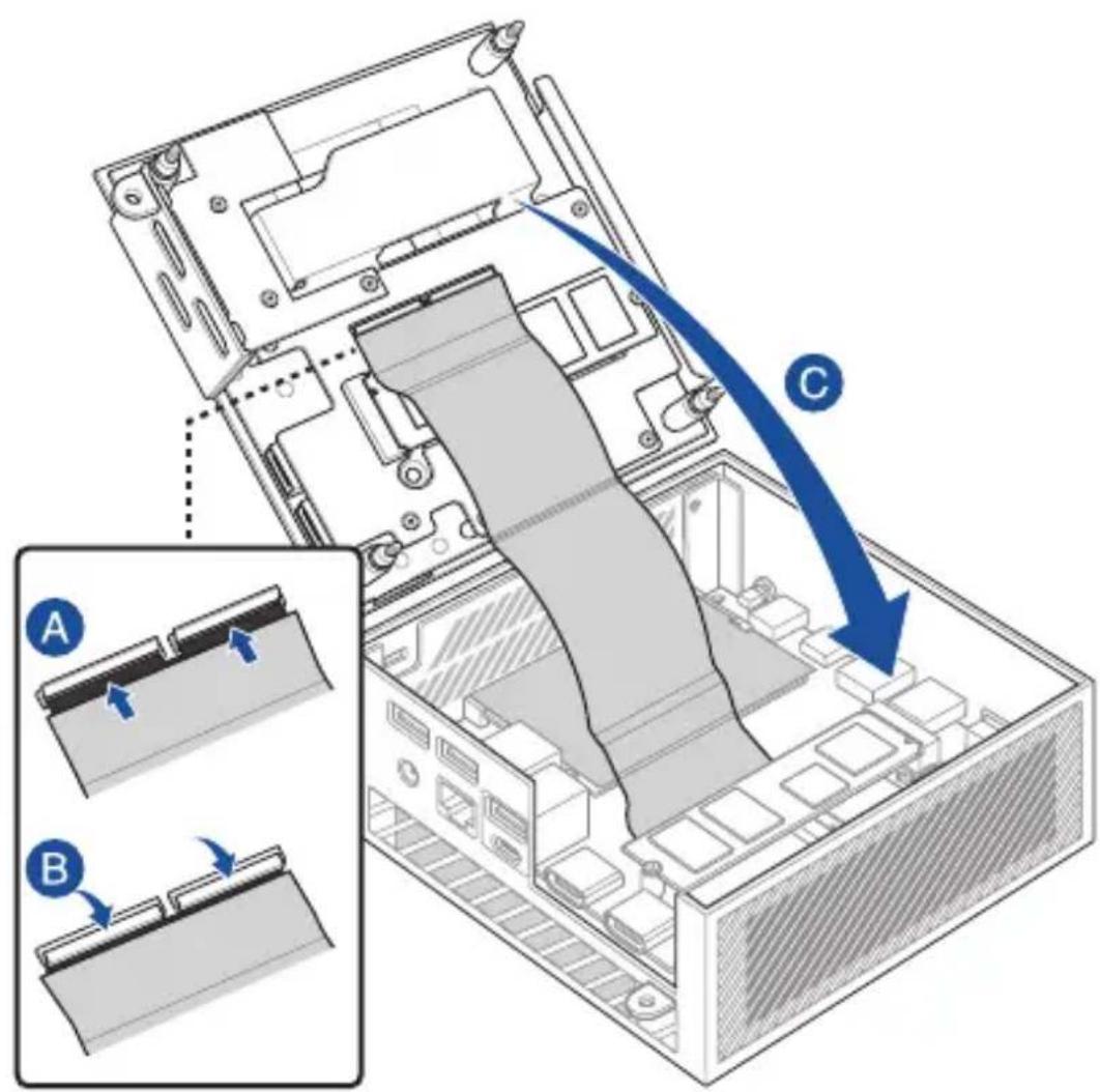
Technical diagram of a computer monitor with labeled components A and B, showing internal structure and directional arrows indicating movement or assembly.Replacing the bottom cover
- Insert the cable into the connectors (A), then close the flaps to secure the cables (B). Close the bottom cover (C).
IMPORTANT! Ensure the PCB gold fingers on the cable are facing the connectors.
text_image
Diagram illustrating a computer motherboard with labeled components A and B, showing internal structure and blue directional arrow indicating flow or movement.- Tighten the four (4) screws on the bottom cover to secure it in place.
natural_image
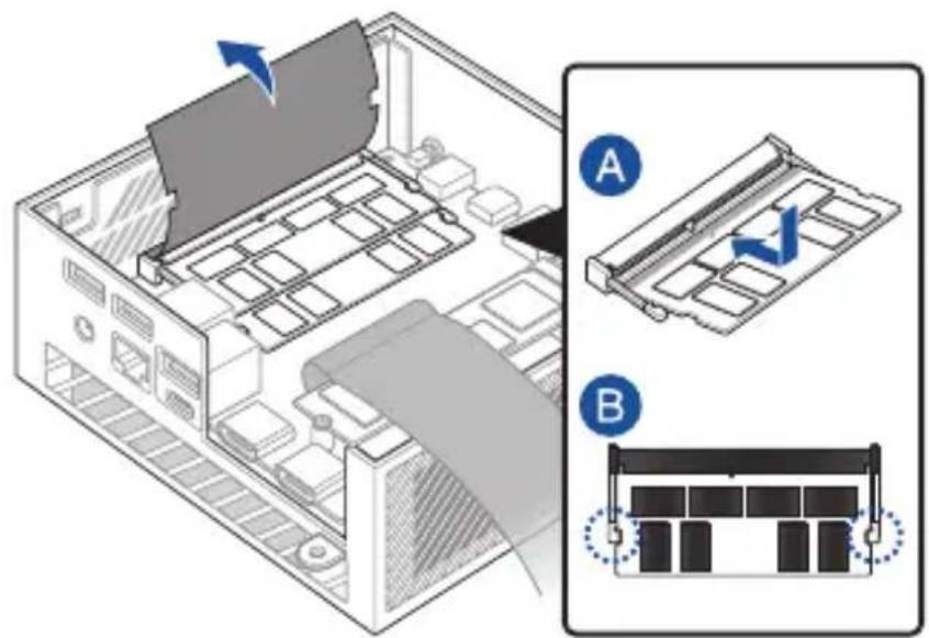
Isometric diagram of a computer tower with ventilation slots and mounting holes (no text or labels)Installing memory modules
Your Mini PC comes with two SO-DIMM memory slots that allow you to install two DDR4 SO-DIMMs.
IMPORTANT! Refer to http://www.asus.com for a list of compatible DIMMs. You can only install DDR4 SO-DIMMs to the Mini PC's DIMM slots.
Align and insert the memory module into the slot (A) and press down (B) until it is securely seated in place. Repeat the same steps to install the other memory module.
text_image
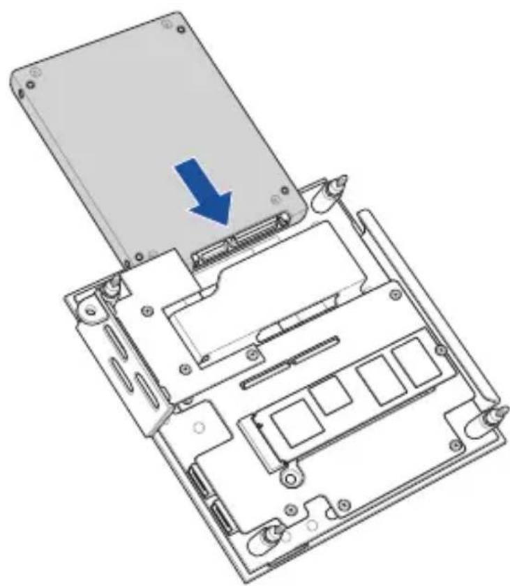
Diagram showing a computer motherboard with labeled components A and B, indicating file orientation and status changes.Installing a 2.5" HDD or SSD
-
Prepare your 2.5" HDD or SSD, then align it with the storage bay on the bottom cover of your Mini PC.
-
Insert your HDD or SSD into the storage bay.
IMPORTANT! This device only supports 7mm and 9.5mm 2.5" HDD or SSD.
natural_image
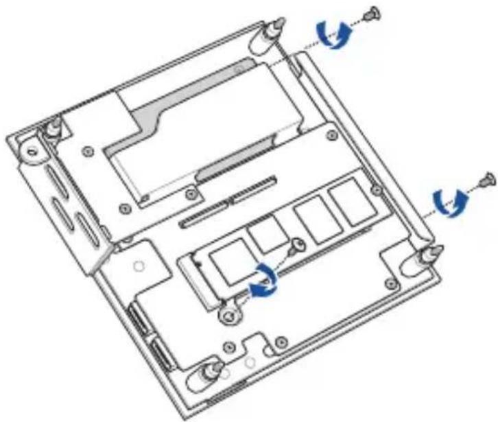
Diagram of a laptop chassis showing the open lid and internal circuitry with a blue arrow indicating a component (no text or symbols present)- Secure the HDD or SSD with three (3) screws.
natural_image
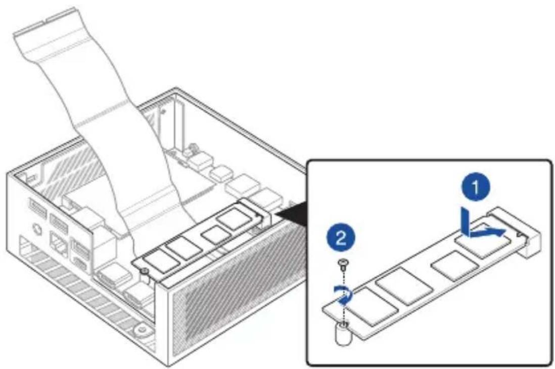
Technical line drawing of a computer motherboard showing internal components and mounting points (no text or symbols)Installing an M.2 SSD
Your Mini PC comes with two M.2 slots; one in the chassis and another on the bottom cover.
To install an M.2 SSD into the chassis
- Align and insert the 2280 M.2 SSD into its slot inside the Mini PC.
- Gently push down the 2280 M.2 SSD on top of the screw hole and fasten it using one of the bundled 3mm round screws.
NOTE: If you wish to install a Gen 4 SSD, ensure to install it to the M.2 slot in the chassis.
text_image
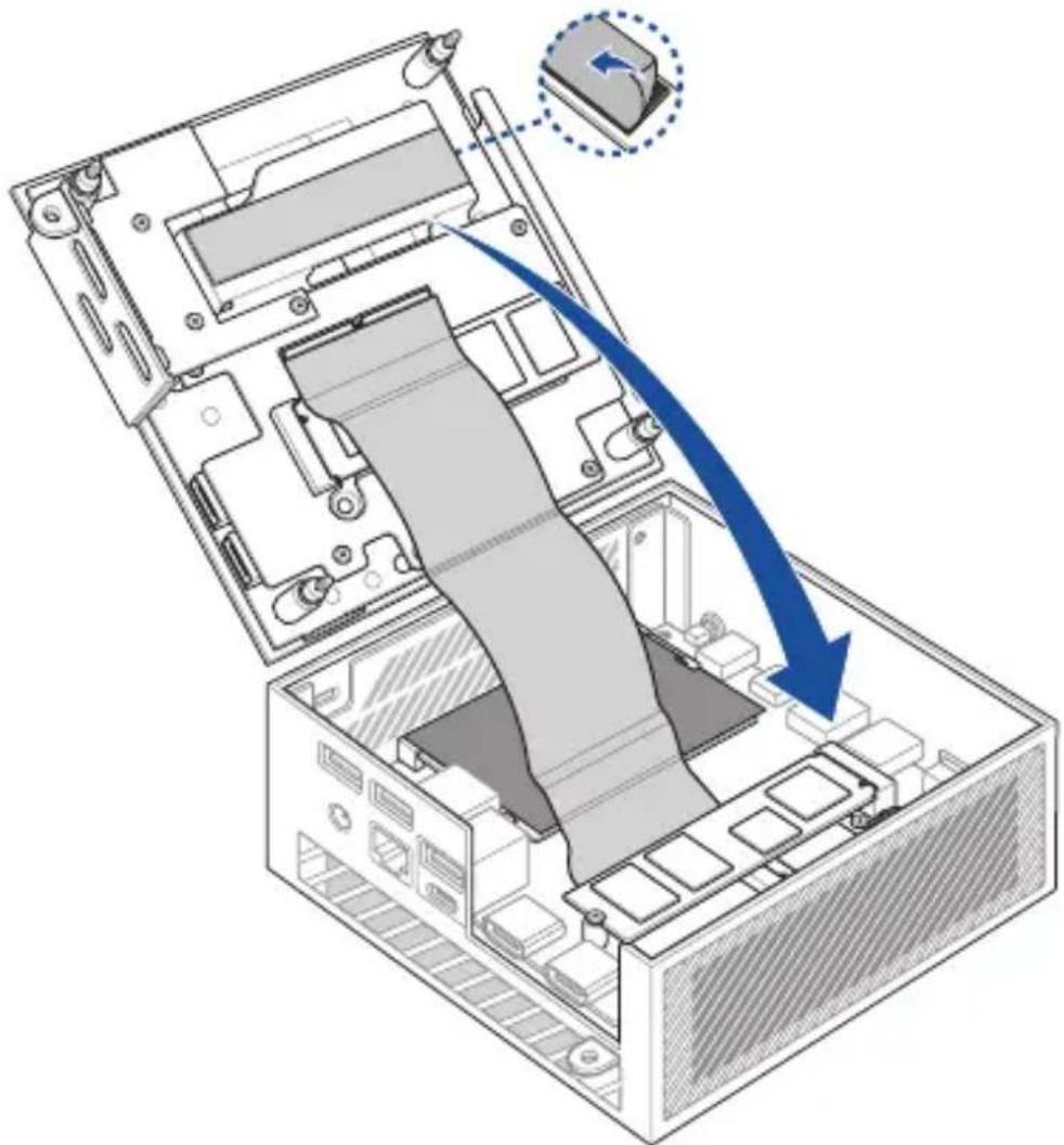
Technical diagram showing a computer motherboard with labeled components and a zoomed-in view of the internal structure.- Before replacing the bottom cover, ensure to remove the plastic film on the thermal pad.
natural_image
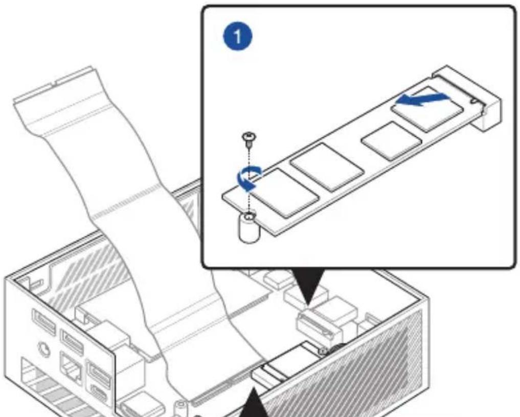
Diagram of an open computer case with a blue arrow indicating compression or disassembly, showing internal components and a close-up inset of a device (no text or symbols present)To install an M.2 SDD to the bottom cover
- Remove the plastic film from the thermal pad.
- Align and insert the 2280 M.2 SSD into its slot on the bottom cover.
- Gently push down the 2280 M.2 SSD on top of the screw hole and fasten it using one of the bundled 3mm round screws.
text_image
Laptop interior diagram with numbered components and directional arrows indicating movement or navigationInstalling a wireless card
NOTE: Your Mini PC includes an M.2 slot for 2230 wireless and Bluetooth modules. Refer to http://www.asus.com for a list of compatible wireless and Bluetooth modules.
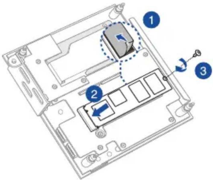
- (optional) Remove the M.2 SSD if an M.2 SSD is installed. To remove the M.2 SSD, remove the screw from the screw hole, then remove the M.2 SSD.
- Remove the M.2 stand screw.
- Align and insert the wireless card into its slot inside the Mini PC.
- Gently push down the wireless card on top of the screw hole and fasten it using the previously removed stand screw.
- (optional) Connect the antennas to your wireless card.
- (optional) Organize your antenna cables with the cable holder clips.
NOTE:
- Connecting antennas to your wireless card may strengthen the wireless signal.
- A soft clicking sound indicates that the antenna has been securely attached to the wireless card.
text_image
Technical diagram showing a computer monitor with labeled parts and a zoomed-in view of the internal structure.
flowchart
graph TD
    A["Step 2: Rotation with clockwise arrow"] --> B["Step 3: Rotation with clockwise arrow"]
    B --> C["Step 4: Rotation with clockwise arrow"]
    C --> D["Step 5: Cable connection to device"]
    D --> E["Step 6: Cable connection to device"]
TPM
4
About the TPM
The system comes with two (2) TPM options: firmware TPM (fTPM) or the discrete TPM (dTPM). The dTPM is an onboard chip and the availability of the onboard dTPM chip may vary between models.
NOTE:
- The fTPM is supported by default, but may not be enabled, for more information on enabling the TPM, please refer to www.asus.com/support.
- The dTPM is optional and is available on selected models
You may use the following methods to check whether your system comes with dTPM:
• Using the Windows Security App
a. Navigate to Start > Settings > Update & Security > Windows Security > Device Security.
b. Check if there is a Security Processor section on this screen, if there is no Security Processor section on this screen, there may not be a dTPM on this model, or the dTPM may be disabled.
• Using the Microsoft Management Console
a. Navigate to Start > Run or press [Windows Key] + R.
b. Type tpm.msc, then choose OK.
c. If you see a message confirming TPM is ready to use, then there is a dTPM available and enabled. If you see a message saying "Compatible TPM cannot be found", there may not be a dTPM on this model, or the dTPM may be disabled.
For more information on TPM, please refer to FAQ at www.asus.com/support/.
Appendix
Safety information
Your Mini PC is designed and tested to meet the latest standards of safety for information technology equipment. However, to ensure your safety, it is important that you read the following safety instructions.


- Do not ingest battery, Chemical Burn Hazard.
- This product contains a coin / button cell battery. If the coin /button cell battery is swallowed, it can cause severe internal burns in just 2 hours and can lead to death.
- Keep new and used batteries away from children.
- If the battery compartment does not close securely, stop using the product and keep it away from children.
- If you think batteries might have been swallowed or placed inside any part of the body, seek immediate medical attention.
Lithium-Ion Battery Warning
CAUTION: Danger of explosion if battery is incorrectly replaced. Replace only with the same or equivalent type recommended by the manufacturer. Dispose of used batteries according to the manufacturer's instructions.
NO DISASSEMBLY
The warranty does not apply to the products that have been disassembled by users
Setting up your system
- Read and follow all instructions in the documentation before you operate your system.
- Do not use this product near water or a heated source.
- Set up the system on a stable surface.
- Openings on the chassis are for ventilation. Do not block or cover these openings. Make sure you leave plenty of space around the system for ventilation. Never insert objects of any kind into the ventilation openings.
- Use this product in environments with ambient temperatures between 0^ and 35^ .
- If you use an extension cord, make sure that the total ampere rating of the devices plugged into the extension cord does not exceed its ampere rating.
- This product should be connected by means of a power cord to a socket-outlet with earthing connection.
- This equipment should be installed and operated with a minimum distance of 20cm between the radiator and your body.
Care during use
- Do not walk on the power cord or allow anything to rest on it.
- Do not spill water or any other liquids on your system.
- When the system is turned off, a small amount of electrical current still flows. Always unplug the power cord from the power outlets before cleaning the system.
-
If you encounter the following technical problems with the product, unplug the power cord and contact a qualified service technician or your retailer.
-
The power cord or plug is damaged.
– Liquid has been spilled into the system. - The system does not function properly even if you follow the operating instructions.
- The system was dropped or the cabinet is damaged.
-
The system performance changes.
-
Avoid contact with hot components inside the Mini PC. During operation, some components become hot enough to burn the skin. Before you open the computer cover, turn off the computer, disconnect the power, and wait approximately 30 minutes for the components to cool.
- Disposal of a battery into fire or a hot oven, or mechanically crushing or cutting of a battery, that can result in an explosion;
• Leaving a battery in an extremely high temperature surrounding environment that can result in an explosion or the leakage of flammable liquid or gas; - A battery subjected to extremely low air pressure that may result in an explosion or the leakage of flammable liquid or gas.
Safety Precautions
Accessories that came with this product have been designed and verified for the use in connection with this product. Never use accessories for other products to prevent the risk of electric shock or fire.
Regulatory notices
COATING NOTICE
IMPORTANT! To provide electrical insulation and maintain electrical safety, a coating is applied to insulate the device except on the areas where the I/O ports are located.
Federal Communications Commission Statement
This device complies with Part 15 of the FCC Rules. Operation is subject to the following two conditions:
- This device may not cause harmful interference, and
- This device must accept any interference received including interference that may cause undesired operation.
This equipment has been tested and found to comply with the limits for a Class B digital device, pursuant to Part 15 of the FCC Rules. These limits are designed to provide reasonable protection against harmful interference in a residential installation.
This equipment generates, uses and can radiate radio frequency energy and, if not installed and used in accordance with manufacturer's instructions, may cause harmful interference to radio communications. However, there is no guarantee that interference will not occur in a particular installation. If this equipment does cause harmful interference to radio or television reception, which can be determined by turning the equipment off and on, the user is encouraged to try to correct the interference by one or more of the following measures:
- Reorient or relocate the receiving antenna.
- Increase the separation between the equipment and receiver.
- Connect the equipment to an outlet on a circuit different from that to which the receiver is connected.
- Consult the dealer or an experienced radio/TV technician for help.
IMPORTANT! Outdoor operations in the 5.15\~5.25 GHz band is prohibited. This device has no Ad-hoc capability for 5250\~5350 and 5470\~5725 MHz.
CAUTION! Any changes or modifications not expressly approved by the grantee of this device could void the user's authority to operate the equipment.
RF exposure warning
This equipment must be installed and operated in accordance with provided instructions and the antenna(s) used for this transmitter must be installed to provide a separation distance of at least 20 cm from all persons and must not be co-located or operating in conjunction with any other antenna or transmitter. End-users and installers must be provide with antenna installation instructions and transmitter operating conditions for satisfying RF exposure compliance.
ISED Radiation Exposure Statement for Canada
This equipment complies with ISED radiation exposure limits set forth for an uncontrolled environment. To maintain compliance with ISED RF exposure compliance requirements, please avoid direct contact to the transmitting antenna during transmitting. End users must follow the specific operating instructions for satisfying RF exposure compliance.
Operation is subject to the following two conditions:
• This device may not cause interference and
- This device must accept any interference, including interference that may cause undesired operation of the device.
HDMI Trademark Notice
The terms HDMI, HDMI High-Definition Multimedia Interface, and the HDMI Logo are trademarks or registered trademarks of HDMI Licensing Administrator, Inc.
Compliance Statement of Innovation, Science and Economic Development Canada (ISED)
This device complies with Innovation, Science and Economic Development Canada licence exempt RSS standard(s). Operation is subject to the following two conditions: (1) this device may not cause interference, and (2) this device must accept any interference, including interference that may cause undesired operation of the device.
CAN ICES-003(B)/NMB-003(B)
Wireless Operation Channel for Different Domains
N. America 2.412-2.462 GHz Ch01 through CH11
Japan 2.412-2.484 GHz Ch01 through Ch14
Europe ETSI 2.412-2.472 GHz Ch01 through Ch13
Declaration of compliance for product environmental regulation
ASUS follows the green design concept to design and manufacture our products, and makes sure that each stage of the product life cycle of ASUS product is in line with global environmental regulations. In addition, ASUS disclose the relevant information based on regulation requirements.
Please refer to http://csr.asus.com/Compliance.htm for information disclosure based on regulation requirements ASUS is complied with:
EU REACH and Article 33
Complying with the REACH (Registration, Evaluation, Authorization, and Restriction of Chemicals) regulatory framework, we publish the chemical substances in our products at ASUS REACH website at http://csr.asus.com/english/REACH.htm
EU RoHS
This product complies with the EU RoHS Directive. For more details, see http://csr.asus.com/english/article.aspx?id=35
ASUS Recycling/Takeback Services
ASUS recycling and takeback programs come from our commitment to the highest standards for protecting our environment. We believe in providing solutions for you to be able to responsibly recycle our products, batteries, other components as well as the packaging materials. Please go to http://csr.asus.com/english/Takeback.htm for detailed recycling information in different regions.
Ecodesign Directive
European Union announced a framework for the setting of ecodesign requirements for energy-related products (2009/125/EC). Specific Implementing Measures are aimed at improving environmental performance of specific products or across multiple product types. ASUS provides product information on the CSR website. The further information could be found at https://csr.asus.com/english/article.aspx?id=1555.
DO NOT throw the device in municipal waste. This product has been designed to enable proper reuse of parts and recycling. This symbol of the crossed out wheeled bin indicates that the product (electrical, electronic equipment, and mercury-containing button cell battery) should not be placed in municipal waste. Check local technical support services for product recycling.
EPEAT (Electronic Product Environmental Assessment Tool) registered products
The public disclosure of key environmental information for ASUS EPEAT registered products is available on CSR web site http://csr.asus.com/english/article.aspx?id=41. More information about EPEAT program and purchaser guidance can be found on the EPEAT website www.epeat.net.
ENERGY STAR complied product
ENERGY STAR is a joint program of the U.S. Environmental Protection Agency and the U.S. Department of Energy helping us all save money and protect the environment through energy efficient products and practices.

text_image
energyENERGY STAR
All ASUS products with the ENERGY STAR logo comply with the ENERGY STAR standard, and the power management feature is enabled by default. The monitor and computer are automatically set to sleep after 10 and 30 minutes of user inactivity. To wake your computer, click the mouse or press any
key on the keyboard.
Please visit http://www.energystar.gov/powermanagement for detail information on power management and its benefits to the environment. In addition, please visit http://www.energystar.gov for detail information on the ENERGY STAR joint program.
NOTE: Energy Star is NOT supported on FreeDOS and Linux-based products.
Simplified EU Declaration of Conformity
ASUSTek Computer Inc. hereby declares that this device is in compliance with the essential requirements and other relevant provisions of Directive 2014/53/EU. Full text of EU declaration of conformity is available at https://www.asus.com/support/.
The WiFi operating in the band 5150-5350 MHz shall be restricted to indoor use for countries listed in the table below:
a. Low Power Indoor (LPI) Wi-Fi 6E devices:
The device is restricted to indoor use only when operating in the 5945 to 6425 MHz frequency range in Belgium (BE), Bulgaria (BG), Cyprus (CY), Czech Republic (CZ), Estonia (EE), France (FR), Iceland (IS), Ireland (IE), Lithuania (LT), Germany (DE), Netherlands (NL), Spain (ES).
b. Very Low Power (VLP) Wi-Fi 6E devices (portable devices):
The device is not permitted to be used on Unmanned Aircraft Systems (UAS) when operating in the 5945 to 6425 MHz frequency range in Belgium (BE), Bulgaria (BG), Cyprus (CY), Czech Republic (CZ), Estonia (EE), France (FR), Iceland (IS), Ireland (IE), Lithuania (LT), Germany (DE), Netherlands (NL), Spain (ES).
| AT BE | BG CZ | DK EE FR | ||||
| DE IS | IE IT EL | ES CY | ||||
| LV | LI | LT | LU | HU | MT | NL |
| NO | PL PT | RO SI S | K TR | |||
| FI SE | CH | HR U | K(NI) |
CE
Service and Support
Visit our multi-language website at https://www.asus.com/support/.

text_image
ASUSMini PC Série PN52
natural_image
Line drawing of a rectangular electronic device with attached cables and ear connectors (no text or symbols)
natural_image
Line drawing of a straight cord with multiple connectors (no text or symbols)Documentation technique
REMARQUES :
text_image
Technical diagram of a mechanical device with labeled components 1, 2, and 31
Anneau de sûreté
natural_image
Cross-sectional diagram of a mechanical component with hatched fill and labeled component 1 (no text or symbols beyond labels)1
text_image
Diagram of a computer interface showing labeled ports and connectors, including VGA, HDMI, and Ethernet ports with numbered annotations.
HDMI
Port HDMI®
text_image
Diagram showing cable connection to a computer with labeled components A and B, and component C connected via cable to a power outlet.REMARQUE :
natural_image
Illustration of a computer power adapter with an attached cable, showing ports and ventilation slots (no text or symbols)natural_image
Illustration of a computer drive with ports and an external cable, showing no text or symbols.natural_image
Diagram of a computer drive showing ports and connectors with a cable inserted (no text or labels)natural_image
Illustration of a computer power drive showing port labels and connections (no text or symbols present)natural_image
Line drawing of a computer setup with a server, mouse, and keyboard (no text or symbols)natural_image
Illustration of a computer setup with a USB drive, mouse, keyboard, and monitor (no text or symbols)Éteindre le mini PC
natural_image
Isometric diagram of a computer tower case with visible internal components and directional arrows indicating rotation (no text or symbols)text_image
Technical diagram of an internal device with labeled components A and B, showing assembly and component disassembly.text_image
Diagram illustrating a computer motherboard with labeled components A and B, showing internal structure and directional arrow C.natural_image
Isometric diagram of a computer tower with ventilation slots and mounting holes (no text or labels)text_image
Diagram showing a computer motherboard with labeled components A and B, indicating file transfer or assembly steps.natural_image
Diagram of a laptop chassis showing the open lid and internal circuit board with a blue arrow indicating a component (no text or symbols present)natural_image
Technical line drawing of a computer motherboard showing internal components and mounting points (no text or symbols)Installer un module M.2 SSD
text_image
Technical diagram showing a computer motherboard with labeled components and a zoomed-in view of the main panel.natural_image
Diagram of an internal computer case with a blue arrow indicating compression or disassembly (no text or symbols present)text_image
Laptop interior diagram with numbered components and directional arrows indicating movement or navigationtext_image
Technical diagram showing a computer monitor with a scroll and a component being inserted, labeled with step number 1.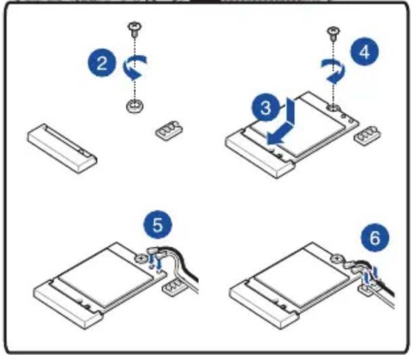
flowchart
graph TD
    A["Step 2: Rotation"] --> B["Step 3: Rotation"]
    B --> C["Step 4: Rotation"]
    C --> D["Step 5: Cable Installation"]
    D --> E["Step 6: Cable Connection"]