ExpertCenter PN64-E1 - Desktop computer ASUS - Free user manual and instructions
Find the device manual for free ExpertCenter PN64-E1 ASUS in PDF.
Download the instructions for your Desktop computer in PDF format for free! Find your manual ExpertCenter PN64-E1 - ASUS and take your electronic device back in hand. On this page are published all the documents necessary for the use of your device. ExpertCenter PN64-E1 by ASUS.
USER MANUAL ExpertCenter PN64-E1 ASUS
Mini PC PN64-E1 Series User ManualCOPYRIGHT INFORMATION No part of this manual, including the products and software described in it, may be reproduced, transmitted, transcribed, stored in a retrieval system, or translated into any language in any form or by any means, except documentation kept by the purchaser for backup purposes, without the express written permission of ASUSTeK COMPUTER INC. (“ASUS”). ASUS PROVIDES THIS MANUAL “AS IS” WITHOUT WARRANTY OF ANY KIND, EITHER EXPRESS OR IMPLIED, INCLUDING BUT NOT LIMITED TO THE IMPLIED WARRANTIES OR CONDITIONS OF MERCHANTABILITY OR FITNESS FOR A PARTICULAR PURPOSE. IN NO EVENT SHALL ASUS, ITS DIRECTORS, OFFICERS, EMPLOYEES OR AGENTS BE LIABLE FOR ANY INDIRECT, SPECIAL, INCIDENTAL, OR CONSEQUENTIAL DAMAGES (INCLUDING DAMAGES FOR LOSS OF PROFITS, LOSS OF BUSINESS, LOSS OF USE OR DATA, INTERRUPTION OF BUSINESS AND THE LIKE), EVEN IF ASUS HAS BEEN ADVISED OF THE POSSIBILITY OF SUCH DAMAGES ARISING FROM ANY DEFECT OR ERROR IN THIS MANUAL OR PRODUCT. Products and corporate names appearing in this manual may or may not be registered trademarks or copyrights of their respective companies, and are used only for identication or explanation and to the owners’ benet, without intent to infringe. SPECIFICATIONS AND INFORMATION CONTAINED IN THIS MANUAL ARE FURNISHED FOR INFORMATIONAL USE ONLY, AND ARE SUBJECT TO CHANGE AT ANY TIME WITHOUT NOTICE, AND SHOULD NOT BE CONSTRUED AS A COMMITMENT BY ASUS. ASUS ASSUMES NO RESPONSIBILITY OR LIABILITY FOR ANY ERRORS OR INACCURACIES THAT MAY APPEAR IN THIS MANUAL, INCLUDING THE PRODUCTS AND SOFTWARE DESCRIBED IN IT. Copyright © 2023 ASUSTeK COMPUTER INC. All Rights Reserved.
LIMITATION OF LIABILITY
Circumstances may arise where because of a default on ASUS’ part or other liability, you are entitled to recover damages from ASUS. In each such instance, regardless of the basis on which you are entitled to claim damages from ASUS, ASUS is liable for no more than damages for bodily injury (including death) and damage to real property and tangible personal property; or any other actual and direct damages resulted from omission or failure of performing legal duties under this Warranty Statement, up to the listed contract price of each product. ASUS will only be responsible for or indemnify you for loss, damages or claims based in contract, tort or infringement under this Warranty Statement. This limit also applies to ASUS’ suppliers and its reseller. It is the maximum for which ASUS, its suppliers, and your reseller are collectively responsible. UNDER NO CIRCUMSTANCES IS ASUS LIABLE FOR ANY OF THE FOLLOWING: (1) THIRD-PARTY CLAIMS AGAINST YOU FOR DAMAGES; (2) LOSS OF, OR DAMAGE TO, YOUR RECORDS OR DATA; OR (3) SPECIAL, INCIDENTAL, OR INDIRECT DAMAGES OR FOR ANY ECONOMIC CONSEQUENTIAL DAMAGES (INCLUDING LOST PROFITS OR SAVINGS), EVEN IF ASUS, ITS SUPPLIERS OR YOUR RESELLER IS INFORMED OF THEIR POSSIBILITY.
Chapter 1: Getting to know your Mini PC
This chapter details the hardware components of your Mini PC.
Chapter 2: Using your Mini PC
This chapter provides you with information on using your Mini PC.
Chapter 3: Upgrading your Mini PC
This chapter provides you with information on how to upgrade the memory modules, wireless modules, and hard disk drive / solid state drive of your Mini PC.
This chapter provides you with information on the TPM options. Appendix This section includes notices and safety statements for your Mini PC.6 PN Series Conventions used in this manual To highlight key information in this manual, some text are presented as follows: IMPORTANT! This message contains vital information that must be followed to complete a task. NOTE: This message contains additional information and tips that can help complete tasks. WARNING! This message contains important information that must be followed to keep you safe while performing certain tasks and prevent damage to your Mini PC's data and components.PN Series 7 Package contents Your Mini PC package contains the following items: ASUS Mini PC PN Series AC power adapter* Power cord* Technical documentation8 PN Series NOTE:
- The most up-to-date and accurate product specications are available on www.asus.com for download.
- Product and accessory images are for illustrative purposes only. The actual appearance and specications may vary depending on the model.
- *The bundled power adapter may vary depending on the model and the country (or region) of sale.
- Some bundled accessories may vary depending on the model. For details on these accessories, refer to their respective user manuals.
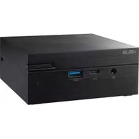
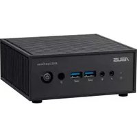
- If the device or its components fail or malfunction during normal and proper use within the warranty period, bring the warranty card to the ASUS Service Center for replacement of the defective components.1 Getting to know your Mini PC10 PN Series Features Front view Drive activity indicator This indicator lights up when your Mini PC is accessing the internal storage drive. Headphone/Headset/Microphone jack (optional) This port allows you to connect amplied speakers or headphones. You can also use this port to connect your headset or an external microphone.PN Series 11 Thunderbolt™ 4 port This Thunderbolt™ 4 port provides the following:
- Transfer rate of up to 40 Gbit/s for Thunderbolt™ 4 devices.
- USB power delivery with a maximum of 5 V / 3 A output. USB 3.2 Gen 2 port The USB 3.2 Gen 2 (Universal Serial Bus) port provides a transfer rate up to 10 Gbit/s. Power button The power button allows you to turn the Mini PC on or o. You can use the power button to put your Mini PC to sleep mode or press it for four (4) seconds to force shutdown your Mini PC.12 PN Series Left view Padlock ring This ring allows you to attach a standard padlock to prevent unauthorized disassembly of your Mini PC. NOTE: The padlock is purchased separately. Kensington security slot The Kensington security slot allows you to secure your Mini PC using Kensington security products. Air vents (intake vent) The air vents allow cooler air to enter your Mini PC chassis. IMPORTANT! For optimal heat dissipation and air ventilation, ensure that the air vents are free from obstructions.PN Series 13 Right view Air vents (intake vent) The air vents allow cooler air to enter your Mini PC chassis. IMPORTANT! For optimal heat dissipation and air ventilation, ensure that the air vents are free from obstructions.14 PN Series Rear view HDMI port The HDMI (High Denition Multimedia Interface) port supports a Full-HD device, such as an LCD TV or monitor, to allow viewing on a larger external display. NOTE: The left HDMI port supports CEC (Consumer Electronics Control). Connect any CEC compatible device that you want to control with a remote control to this port, and make sure that the device’s HDMI-CEC is enabled. When using only this port as a display output source, this port will support a resolution of up to 3840 x 2160 @60Hz. The resolution may also be aected by the cabling and output device.PN Series 15 Air vents (exhaust vent) The air vents allow your Mini PC chassis to expel hot air. IMPORTANT! For optimal heat dissipation and air ventilation, ensure that the air vents are free from obstructions. Congurable port This port varies between models and consists of the following port options: NOTE: This port may vary depending on model. HDMI port The HDMI (High Denition Multimedia Interface) port supports a Full-HD device, such as an LCD TV or monitor to allow viewing on a larger external display. NOTE: When using only this port as a display output source, this port will support a resolution of up to 7680 x 4320 @30Hz. The resolution may also be aected by the cabling and output device. DisplayPort This port allows you to connect your Mini PC to an external display. NOTE: When using only this port as a display output source, this port will support a resolution of up to 5120 x 2880 @60Hz. The resolution may also be aected by the cabling and output device.16 PN Series VGA port This port allows you to connect your Mini PC to an external display. NOTE: When using only this port as a display output source, this port will support a resolution of up to 1920 x 1200 @60Hz. The resolution may also be aected by the cabling and output device. Serial (COM) connector The 9-pin serial (COM) connector allows you to connect devices that have serial ports, such as mouse, modem, and printers. LAN port The 8-pin RJ-45 LAN port supports a standard Ethernet cable for 10/100/1000/2500 Mbps connection to a local network.PN Series 17 Thunderbolt™ 4 with Power Delivery input port This Thunderbolt™ 4 port provides the following:
- Transfer rate of up to 40 Gbit/s for Thunderbolt™ 4 devices.
- USB power delivery with a maximum of 5 V / 3 A output.
- Support for power (DC) input when connected to an external device that is PD (Power Delivery) compliant with a 20 V / 5 A output. CAUTION!
- DO NOT connect your Mini PC to a device that supports less than 20 V / 5 A PD when using the Thunderbolt™ 4 port as a power (DC) input port. Doing so may cause problems when powering on your Mini PC.
- Always disconnect the charging cable from the power (DC) input port before using the Thunderbolt™ 4 port for power input.
- Make sure to power o your device when switching between the Thunderbolt™ 4 and power input ports. USB 3.2 Gen 2 port The USB 3.2 Gen 2 (Universal Serial Bus) port provides a transfer rate up to 10 Gbit/s. USB 3.2 Gen 1 port The USB 3.2 Gen 1 (Universal Serial Bus) port provides a transfer rate up to 5 Gbit/s.18 PN Series Power input The supplied power adapter converts AC power to DC power for use with this jack. Power supplied through this jack supplies power to the Mini PC. To prevent damage to the Mini PC, always use the supplied power adapter. WARNING! The power adapter may become warm to hot when in use. Do not cover the adapter and keep it away from your body. NOTE: Please refer to the following information on the power adapter: 120 W Power adapter: +20 Vdc 6 A, 120 W 120 W Power adapter: +19 Vdc 6.32 A, 120 W LAN port The 8-pin RJ-45 LAN port supports a standard Ethernet cable for 10/100/1000/2500 Mbps connection to a local network.2 Using your Mini PC20 PN Series Getting started Connect the AC power adapter to your Mini PC To connect the AC power adapter to your Mini PC: A. Connect the power cord to the AC power adapter. B. Connect the DC power connector into your Mini PC’s power (DC) input. C. Plug the AC power adapter into a 100V~240V power source. NOTE: The power adapter may vary in appearance, depending on the model and your region.PN Series 21 NOTE: Please refer to the following for more information on the adapter: 120 W Power adapter
- Rating output current: 6 A (120 W)
- Rating output voltage: 20 V 150 W Power adapter
- Rating output current: 6.32 A (120 W)
- Rating output voltage: 19 V22 PN Series Connect a display panel to your Mini PC You can connect a display panel or projector to your Mini PC that has the following port:
- Up to ve display panels may be connected, depending on model and selected options*. However, only a maximum of four can be displayed simultaneously.
- Using one of the ports listed below as the only display output source will provide the following maximum resolution**: - HDMI port Supports a resolution of up to 3840 x 2160 @60Hz. - Thunderbolt™ 4 port Supports a resolution of up to 5120 x 2880 @60Hz. - Congurable VGA port Supports a resolution of up to 1920 x 1200 @60Hz. - Congurable HDMI port Supports a resolution of up to 7680 x 4320 @30Hz. - Congurable DisplayPort port Supports a resolution of up to 5120 x 2880 @60Hz.
- The ports may vary per model. Please refer to the Features section for the location of the ports. ** The maximum resolution may be aected by the cabling and output device. To connect a display panel to your Mini PC:PN Series 23 Connect display via HDMI port Connect display via DisplayPort Connect one end of an HDMI, VGA, DisplayPort, or Thunderbolt™ 4 cable to an external display, and the other end of the cable to your Mini PC’s HDMI port, VGA port, DisplayPort, or Thunderbolt™ 4 port.24 PN Series Connect display via Thunderbolt™ 4 port Connect display via VGA portPN Series 25 Connect the USB cable from keyboard or mouse You can connect generally any USB keyboard and mouse to your Mini PC. You can also connect a USB dongle for a wireless keyboard and mouse set. To connect a keyboard and mouse to your Mini PC: Connect the USB cable from your keyboard and mouse to any of the USB ports of your Mini PC. NOTE: The keyboard varies with country and/or region.26 PN Series Turn on your Mini PC Press the power button to turn on your Mini PC.PN Series 27 Turning o your Mini PC If your Mini PC is unresponsive, press and hold the power button for at least four (4) seconds until your Mini PC turns o. Putting your Mini PC to sleep To set your Mini PC to enter Sleep mode by pressing the Power button once, search for Control Panel in the Windows Search Box, then navigate to Hardware and Sound > Power Options > Choose what the power button does, and set When I press the power button to Sleep. Entering BIOS Setup BIOS (Basic Input and Output System) stores system hardware settings that are needed for system startup on the Mini PC. Under normal circumstances, the default BIOS settings apply to most conditions to ensure optimal performance. Do not change the default BIOS settings except in the following circumstances:
- An error message appears on the screen during the system bootup and requests you to run BIOS Setup.
- You have installed a new system component that requires further BIOS settings or update. WARNING! Inappropriate BIOS settings may result in instability or boot failure. We strongly recommend that you change the BIOS settings only with the help of a trained service personnel.28 PN Series Load default BIOS settings To load the default values for each of the parameters in your BIOS:
1. Enter the BIOS by pressing <F2> or <DEL> from the POST screen.
NOTE: POST (Power-On Self Test) is a series of software controlled diagnostic tests that run when you turn on your Mini PC.
Upgrading your Mini PC30 PN Series IMPORTANT!
- It is recommended that you install or upgrade the memory modules, wireless card, and solid state drive (SSD) under professional supervision. Visit an ASUS service center for further assistance.
- Ensure that your hands are dry before proceeding with the rest of the installation process. Before installing any of the features in this guide, use a grounded wrist strap or touch a safely grounded object or metal object to avoid damaging them due to static electricity. NOTE: The illustrations in this section are for reference only. The slots may vary depending on model.PN Series 31 Removing the bottom cover
1. Turn o your Mini PC then disconnect all cables and peripherals.
2. Place the Mini PC on a at stable surface with its top side facing down.
3. Completely loosen the four (4) screws from the bottom cover.32 PN Series
4. Slowly and with extreme care, lift the bottom cover in the direction shown
in the illustration (A), then ip the connector aps open (B) and remove the cable (C).PN Series 33
1. Insert the cable into the connectors (A), then close the aps to secure the
cables (B). Close the bottom cover (C). IMPORTANT! Ensure the PCB gold ngers on the cable are facing the connectors. Replacing the bottom cover34 PN Series
2. Tighten the four (4) screws on the bottom cover to secure it in place.PN Series 35
Installing memory modules Your Mini PC comes with two SO-DIMM memory slots that allow you to install two DDR5 SO-DIMMs. IMPORTANT! Refer to https://www.asus.com for a list of compatible DIMMs. You can only install DDR5 SO-DIMMs to the Mini PC’s DIMM slots. Align and insert the memory module into the slot (A) and press down (B) until it is securely seated in place. Repeat the same steps to install the other memory module.36 PN Series Installing a 2.5” HDD or SSD
1. Prepare your 2.5” HDD or SSD, then align it with the storage bay on the
bottom cover of your Mini PC.
2. Insert your HDD or SSD into the storage bay.
IMPORTANT! This device only supports 7mm 2.5” HDD or SSD.PN Series 37
3. Secure the HDD or SSD with three (3) screws.38 PN Series
Installing an M.2 SSD Your Mini PC comes with two M.2 slots; one in the chassis and another on the bottom cover. To install an M.2 SSD into the chassis
1. Align and insert the 2280 M.2 SSD into its slot inside the Mini PC.
2. Gently push down the 2280 M.2 SSD on top of the stando and fasten it
using one of the bundled 3mm screws.PN Series 39
3. Before replacing the bottom cover, ensure to remove the plastic lm on the
thermal pad.40 PN Series To install an M.2 SDD to the bottom cover
1. Remove the plastic lm from the thermal pad.
2. Align and insert the 2280 M.2 SSD into its slot on the bottom cover.
3. Gently push down the 2280 M.2 SSD on top of the stando and secure it
using one of the bundled screws. NOTE:
- The specications for the thermal pad used in this Mini PC is as follows: Thickess: 2.0mm Size: 66mm x 20mm Thermal conductivity: 1.2 W/ mK Hardness: < 50 Sc
- Heat dissipation performance may still vary even when you have replaced the thermal pad with one that meets the above specications. To prevent possible damage to the M.2 SSD, you should have the thermal pad replaced by a service center near you. Thermal pad Plastic lmPN Series 41 Installing a wireless card NOTE: Your Mini PC includes an M.2 slot for 2230 wireless and Bluetooth modules. Refer to https://www.asus.com for a list of compatible wireless and Bluetooth modules.
2. Align and insert the wireless card into its slot inside the Mini PC.
3. Gently push down the wireless card on top of the stando and fasten it
using the previously removed screw.
4. (optional) Connect the antennas to your wireless card.
5. (optional) Organize your antenna cables with the cable holder clips.
- Connecting antennas to your wireless card may strengthen the wireless signal.
- A soft clicking sound indicates that the antenna has been securely attached to the wireless card.42 PN Series4 TPM44 PN Series About the TPM The system comes with two (2) TPM options: rmware TPM (fTPM) or the discrete TPM (dTPM). The dTPM is an onboard chip and the availability of the onboard dTPM chip may vary between models. NOTE:
- The fTPM is supported by default, but may not be enabled, for more information on enabling the TPM, please refer to www.asus.com/support.
- The dTPM is optional and is available on selected models You may use the following methods to check whether your system comes with dTPM:
- Using the Windows Security App a. Navigate to Start > Settings > Update & Security > Windows Security > Device Security. b. Check if there is a Security Processor section on this screen, if there is no Security Processor section on this screen, there may not be a dTPM on this model, or the dTPM may be disabled.
- Using the Microsoft Management Console a. Navigate to Start > Run or press [Windows Key] + R. b. Type tpm.msc, then choose OK. c. If you see a message conrming TPM is ready to use, then there is a dTPM available and enabled. If you see a message saying “Compatible TPM cannot be found”, there may not be a dTPM on this model, or the dTPM may be disabled. For more information on TPM, please refer to FAQ at www.asus.com/support/.Appendix46 PN Series Safety information Your Mini PC is designed and tested to meet the latest standards of safety for information technology equipment. However, to ensure your safety, it is important that you read the following safety instructions.
- Do not ingest battery, Chemical Burn Hazard.
- This product contains a coin / button cell battery. If the coin / button cell battery is swallowed, it can cause severe internal burns in just 2 hours and can lead to death.
- Keep new and used batteries away from children.
- If the battery compartment does not close securely, stop using the product and keep it away from children.
- If you think batteries might have been swallowed or placed inside any part of the body, seek immediate medical attention. NO DISASSEMBLY The warranty does not apply to the products that have been disassembled by users Lithium-Ion Battery Warning CAUTION: Danger of explosion if battery is incorrectly replaced. Replace only with the same or equivalent type recommended by the manufacturer. Dispose of used batteries according to the manufacturer’s instructions.PN Series 47 Setting up your system
- Read and follow all instructions in the documentation before you operate your system.
- Do not use this product near water or a heated source.
- Set up the system on a stable surface.
- Openings on the chassis are for ventilation. Do not block or cover these openings. Make sure you leave plenty of space around the system for ventilation. Never insert objects of any kind into the ventilation openings.
- Use this product in environments with ambient temperatures between 0˚C and 35˚C.
- If you use an extension cord, make sure that the total ampere rating of the devices plugged into the extension cord does not exceed its ampere rating.
- This product should be connected by means of a power cord to a socket- outlet with earthing connection.
- This equipment should be installed and operated with a minimum distance of 20cm between the radiator and your body.48 PN Series Care during use
- Do not walk on the power cord or allow anything to rest on it.
- Do not spill water or any other liquids on your system.
- When the system is turned o, a small amount of electrical current still ows. Always unplug the power cord from the power outlets before cleaning the system.
- If you encounter the following technical problems with the product, unplug the power cord and contact a qualied service technician or your retailer. – The power cord or plug is damaged. – Liquid has been spilled into the system. – The system does not function properly even if you follow the operating instructions. – The system was dropped or the cabinet is damaged. – The system performance changes.
- Avoid contact with hot components inside the Mini PC. During operation, some components become hot enough to burn the skin. Before you open the computer cover, turn o the computer, disconnect the power, and wait approximately 30 minutes for the components to cool.
- Disposal of a battery into re or a hot oven, or mechanically crushing or cutting of a battery, that can result in an explosion;
- Leaving a battery in an extremely high temperature surrounding environment that can result in an explosion or the leakage of ammable liquid or gas;
- A battery subjected to extremely low air pressure that may result in an explosion or the leakage of ammable liquid or gas. Safety Precautions Accessories that came with this product have been designed and veried for the use in connection with this product. Never use accessories for other products to prevent the risk of electric shock or re.PN Series 49 Regulatory notices COATING NOTICE IMPORTANT! To provide electrical insulation and maintain electrical safety, a coating is applied to insulate the device except on the areas where the I/O ports are located. RF exposure warning This equipment must be installed and operated in accordance with provided instructions and the antenna(s) used for this transmitter must be installed to provide a separation distance of at least 20 cm from all persons and must not be co-located or operating in conjunction with any other antenna or transmitter. End- users and installers must be provide with antenna installation instructions and transmitter operating conditions for satisfying RF exposure compliance.50 PN Series Compliance Statement of Innovation, Science and Economic Development Canada (ISED) This device complies with Innovation, Science and Economic Development Canada licence exempt RSS standard(s). Operation is subject to the following two conditions: (1) this device may not cause interference, and (2) this device must accept any interference, including interference that may cause undesired operation of the device. CAN ICES-003(B)/NMB-003(B) ISED Wi-Fi 6E Caution Statement (RLAN devices) Devices shall not be used for control of or communications with unmanned aircraft systems. ISED Radiation Exposure Statement for Canada This equipment complies with ISED radiation exposure limits set forth for an uncontrolled environment. To maintain compliance with ISED RF exposure compliance requirements, please avoid direct contact to the transmitting antenna during transmitting. End users must follow the specic operating instructions for satisfying RF exposure compliance. Operation is subject to the following two conditions:
- This device may not cause interference and