FG 8210 - Generator VOLTCRAFT - Free user manual and instructions
Find the device manual for free FG 8210 VOLTCRAFT in PDF.
| Product type | Function generator |
| Brand | Voltcraft |
| Model | FG 8210 |
| Frequency range | 100 mHz to 10 MHz (sine, square, triangle) |
| Frequency accuracy | ±2% (of measurement range) |
| Waveforms | Sine, square, triangle, DC |
| Output impedance | 50 ohms ±5% |
| Max amplitude | 20 Vpp (no termination), 10 Vpp into 50 ohms |
| Attenuator | -20 dB |
| DC offset | ±10 V (no termination), ±5 V into 50 ohms |
| Symmetry adjustment | 1:1 to 10:1 (up to 100 kHz) |
| VCF input | 0 - 10 V DC/AC, ratio 10:1 max |
| Synchronous TTL output | Fixed TTL level, rise/fall time <25 ns at 1 MHz |
| Sweep function | Linear mode, width 1:1 to 100:1, rate 20 ms to 2 s |
| Built-in frequency counter | 2 Hz - 100 MHz, sensitivity 100 mVrms, protection 250 Vpp |
| Display | 7-digit green LED |
| Power supply | 206 - 252 V AC, 50/60 Hz; 115 V also (switchable) |
| Fuse | F250 mA / 250 V (230 V) or F500 mA / 250 V (115 V), 5x20 mm |
| Power consumption | 20 W |
| Measurement category | CAT II 250 V |
| Operating temperature | 0 °C to 40 °C |
| Relative humidity | Max 85%, non-condensing |
| Dimensions (W x H x D) | 240 x 90 x 270 mm |
| Weight | Approximately 3 kg |
| Maintenance | Clean with dry antistatic cloth; user-replaceable fuse |
| Supplied accessories | Power cord, BNC lead with crocodile clips, spare fuse |
Frequently Asked Questions - FG 8210 VOLTCRAFT
User questions about FG 8210 VOLTCRAFT
0 question about this device. Answer the ones you know or ask your own.
Ask a new question about this device
Download the instructions for your Generator in PDF format for free! Find your manual FG 8210 - VOLTCRAFT and take your electronic device back in hand. On this page are published all the documents necessary for the use of your device. FG 8210 by VOLTCRAFT.
USER MANUAL FG 8210 VOLTCRAFT
FUNKTIONSGENERATOR FG 8210
FUNCTION GENERATOR FG 8210
GB OPERATING INSTRUCTIONS PAGE 22-40
GÉNÉRATEUR DE FONCTIONS FG 8210
(F) NOTICE D'EMPLOI PAGE 41-59
FUNCTIEGENERATOR FG 8210
www.business.conrad.at
natural_image
Pure electrical circuit lines without any symbolsThank you for making the excellent decision of purchasing this Voltcraft® product.
You have acquired a quality product from a brand family which has distinguished itself in the fields of measuring, charging and grid technology thanks to its particular expertise and its continuous innovation.
With Voltcraft®, you will be able to cope even with difficult tasks as an ambitious hobbyist or as a professional user. Voltcraft® offers reliable technology at a great price-performance-ratio.
We are positive: Starting to work with Voltcraft will also be the beginning of a long, successful relationship.
Enjoy your new Voltcraft® product!
These operating instructions are part of this product. They contain important notes on commissioning and handling. Also consider this if you pass on the product to any third party. Therefore, retain these operating instructions for reference!
If there are any technical questions, contact:
Germany: Tel. no.: +49 9604 / 40 88 80
Fax. no.: +49 9604 / 40 88 48
E-mail: tkb@conrad.de
Mon. to Thur. 8.00am to 4.30pm, Fri. 8.00am to 2.00pm
2. TABLE OF CONTENTS
Page
- Introduction....22
- Table of Contents.... 23
- Intended Use 24
- Scope of Delivery 24
- Control Elements 25
- Safety Information 26
- Commissioning....28
7.1 Pre-setting of the Mains Voltage 28
7.2 Connection of the Mains Cable 28
7.3 Switching On/Off 28
7.4 Basic Setting 28
- Measuring....29
8.1 Function Generator 29
8.2 "Pulse" Generator 31
8.3 TTL-Synchronous Output 32
8.4 FM Signal Generator....33
8.5 Voltage-Controlled Frequency Setting "VCF" 34
8.6 "Programmed" Frequency Setting 35
8.7 Wobbulator (Sweep) 35
8.8 Externally Controlled Wobbulator 36
8.9 Frequency Counter 36
- Maintenance and Cleaning....37
9.1 Fuse Change....37
- Disposal....38
- Troubleshooting 38
- Technical Data 39
3. INTENDED USE
The function generator FG 8210 generates measuring signals from 100 mHz up to 10 MHz with different signal forms and adjustable amplitude and symmetry. The display shows the functions.
The following functions are available:
- Signal forms: Sine, rectangle, triangle, DC
- TTL-synchronous output
- Linear wobble function
- DC offset setting
- Voltage-controlled frequency setting (VCF)
- Frequency counter up to 100 MHz
The measuring connection is established via the BNC measuring sockets. The outer conductors of the BNC contacts are all connected to the ground potential of the protective ground.
The maximum input values as compared to earth potential must not be exceeded.
To comply with the specifications, the device must be switched on at least 30 minutes before the measurement starts.
For use in dry indoor areas only.
The product is set up according to protection class 1. The voltage source must be a proper mains socket of the public mains with a ground contact. The mains socket must be close to the device and easily accessible or must have an emergency stop device.
Operation under unfavourable ambient conditions is not permitted. Unfavourable ambient conditions are:
- Dampness or too high humidity
- Dust and flammable gases, vapours or solvents.
- Thunderstorms or similar conditions such as strong electrostatic fields, etc.
Any use other than that described above damages the product. Moreover, this is linked to dangers such as short circuit, fire, electric shock, etc. No part of the product must be modified or converted! Always observe the safety information!
4. SCOPE OF DELIVERY
• Function Generator FG 8210
• BNC-measuring line (BNC → alligator clamps)
- Mains cable
- Spare fuse
5. CONTROL ELEMENTS
(See fold-out page)
1 Carry handle and setup bracket (adjustable). The inclination of the generator can be adjusted by pulling the two holders apart and turning.
2 Display, 7-digit (LED)
3 System displays mHz Milli-Hertz (exp. -3) Hz Hertz (el. unit of frequency) kHz Kilohertz (exp. 3) MHz Megahertz (exp. 6)
G.T Display of the gate time (measuring impulse, G.T = Gate-Time)
4 BNC-socket for the frequency counter input (EXT COUNT IN)
The maximum input voltage is 250 Vpp.
5 BNC-input socket for the voltage-controlled frequency setting (VCF IN)
The maximum input voltage is 10 VDC!
6 BNC-socket for synchronous output (TTL-level)
7 BNC-socket for signal output (50 Ohm impedance)
8 ATT-switch for signal weakening (dampening -20 dB) at the output (7)
9 Setting controller for amplitude (signal voltage)
10 Switch for the output signal form (sine/triangle/rectangle)
11 Adjustment button with double function for the DC-offset
pushed: neutral DC-offset setting (middle position)
pulled: manual offset setting, movement of the signal progress upwards (+/positive) or downwards (-/negative)
12 Adjustment button with double function for the symmetry setting pushed: Symmetry setting neutral pulled: Manual symmetry adjustment possible, e.g. setting of pulse/pause ratio
13 Area selection buttons for the frequency control area (display x1 Hz to x1 MHz) 14 Adjustment button with double function for the wobble function pushed: Wobble function off pulled: Wobble function on with option of setting the bandwidth (Width)
15 Adjustment button for setting the wobble speed (Rate) 16 Fine adjustment controller for the generator frequency setting 17 LPF-button for low-pass frequency filter in the counter operation (for measurements in the NF range) INT/EXT switching button for display (display of the internal generator frequency or the external counter frequency)
18 Gross adjustment controller for the generator frequency setting 19 Mains switch for commissioning (ON / OFF) 20 Ventilator opening for device cooling
21 Operating mass (earthing) e.g. for ESD protective measures or other devices
22 Fuse holder for mains protection
23 Protective contact non-heating connection (mains connection, IEC C14)
24 Selection switch for mains voltage (230 V or 115 V)
6. SAFETY INFORMATION

Please read the operating instructions completely before taking the device into operation. They contain important information for correct operation.
The guarantee/warranty will expire if damage is incurred resulting from non-compliance with the operating instructions! We do not assume any liability for consequential damage!
We do not assume any liability for property damage and personal injury caused by improper use or non-compliance with the safety instructions! In such cases, any warranty/guarantee will expire.
- This device left the manufacturer's factory in safe and perfect condition.
To maintain this condition and to ensure safe operation, the user must observe the safety information and warning notes in these operating instructions.
Observe the following symbols:

An exclamation mark in a triangle shows important notes in these operating instructions that must be strictly observed.

The triangle containing a lightning symbol warns against danger of electrical shock or impairment of the electrical safety of the device.
→ The “arrow” symbol indicates that special advice and notes on operation are provided here.

Earth potential

Protective ground
CE This device is CE-compliant and meets the applicable European directives.
- CAT II Measuring category II for measurements on electric and electronic devices connected to the mains supply with a mains plug. This category also covers all lower categories (e.g. CAT I for measuring signal and control voltages).
- CAT III Measuring category III for measuring in building installation (e.g. outlets or sub-distribution). This category also covers all lower categories (e.g. CAT II for measuring electronic devices). The frequency generator must not be used in the measuring category CAT III.
- Meters and accessories are not toys and have no place in the hands of children!
- In commercial institutions, the accident prevention regulations of the Employer's Liability Insurance Association for Electrical Systems and Operating Materials are to be observed.
- In schools, training centres, computer and self-help workshops, handling of meters must be supervised by trained personnel in a responsible manner.
- Never touch the device with wet or damp hands. There is a risk of potentially fatal electric shock.
- Handle the product with care. Impact, blows or falls from even a low height may damage the product.
- The device must only be opened by a specialist. Live components may be exposed if covers are opened or parts are removed (unless this can be done without tools). Capacitors inside the device may still carry voltage even though the device has been disconnected from all power sources. Disconnect the device from all meters and voltage sources before opening it.
- Do not switch the device on immediately after taking it from a cold to a warm environment. The condensation that forms might destroy your device under detrimental conditions. Allow the device to reach room temperature before switching it on.
- The device generates heat during operation; ensure that it is adequately ventilated. Ventilation slots must not be covered!
- Only fuses of the indicated type and rated current must be used. Use of patched fuses is forbidden.
- The function generator is not designed for attaching to humans or animals.
- Be especially careful when dealing with voltages higher than 50 V alternating (AC) or 75 V direct voltage (DC). Even at these voltages it is possible to receive a potentially fatal electric shock if you touch electrical conductors.
- Before each measurement, check your function generator or your measuring lines (scanner heads, BNC cables) and your mains line for damage. Damaged parts and accessories must no longer be used. Securing measures are necessary before repeated use.
- To avoid electric shock, observe that you do not touch the scanning head tip(s) or alligator clamps, not even indirectly, while the BNC lines and the connections to be measured (measuring points) are open.
- Protect the product from extreme temperatures direct sunlight, high humidity, moisture, flammable gases, vapours and solvents.
- Never pour any liquids over electrical devices or put objects filled with liquid on top of them (e. g. glasses).
- Do not operate the device in rooms or under unfavourable conditions where combustible gases, vapours or dusts are or may be present.
- When secure operation is no longer possible, shut off the product and protect it from inadvertent use. Secure operation is no longer warranted if the product:
- has visible damage,
- no longer works properly,
- was stored under detrimental ambience conditions for an extended period or
- was subjected to considerable transport strain.
- Also observe the safety information in the different chapters of in the operating instructions of the connected devices.
- Warning! This is a class-A-facility. This facility may cause radio interferences in the residential area. In this case, the operator may be required to take appropriate measures.
7. COMMISSIONING
7.1 PRE-SETTING OF THE MAINS VOLTAGE
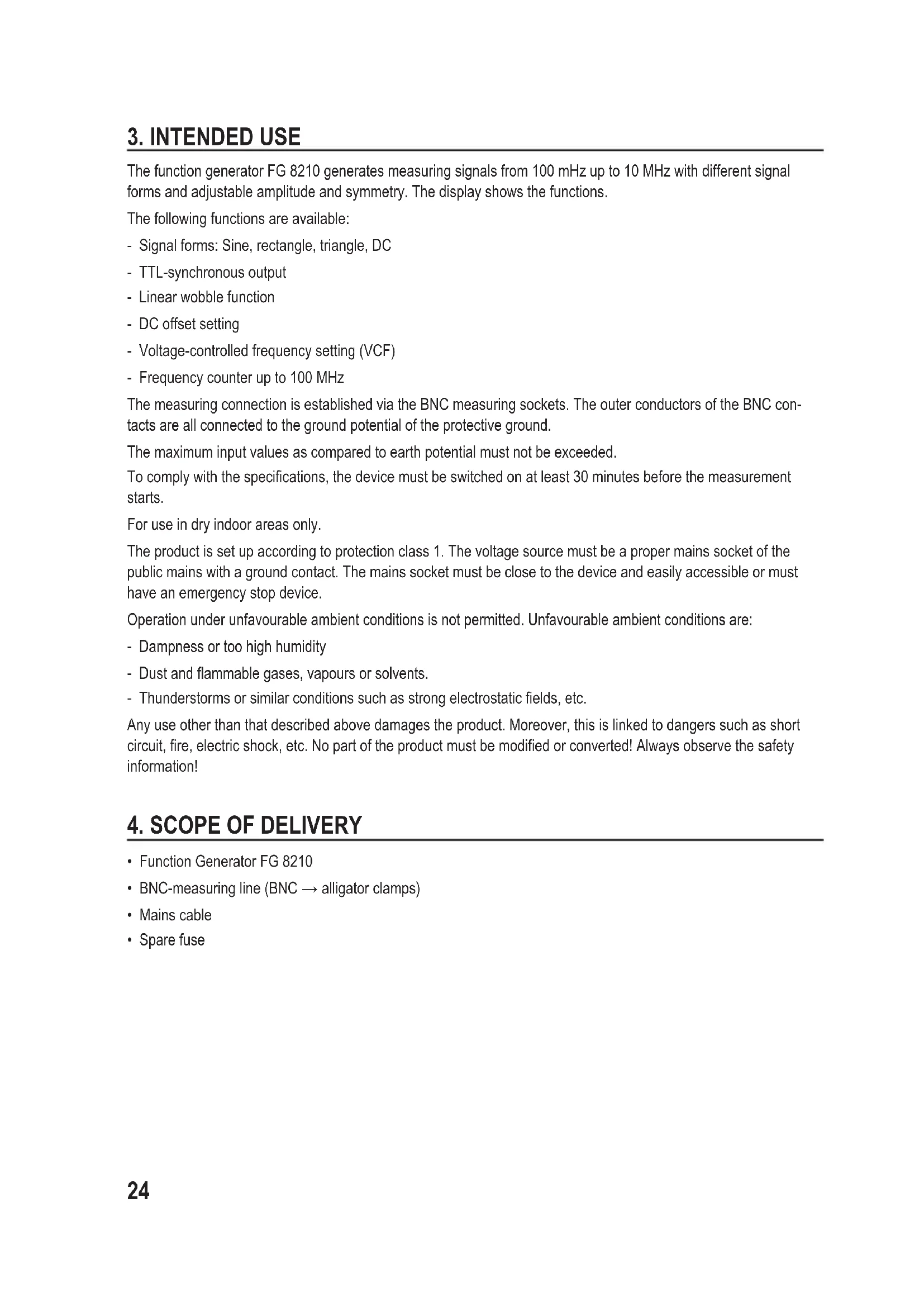
- Before first commissioning, observe that the rear selection switch for the mains voltage (24) is in the correct position.
- For Europe, set "230V"
115 V

230 V
115 V
230 V
7.2 CONNECTION OF THE POWER CABLE
- Connect the supplied grounding mains cable to the mains connection socket (21) on the function generator. Ensure a tight fit.
- Connect the mains cable to a protective contact socket with protective ground.
7.3 SWITCHING ON/OFF
- Push the mains switch (19) to switch the generator on or off. The device is switched on when it is pushed.
- After activation, a self test runs that is indicated by all display segments lighting up. After the test, the generator is ready for use. Observe a heat up phase of at least 30 minutes before taking up the measurements.
7.4 BASIC SETTING
- To be certain that the output signal is symmetric as well as uninfluenced by the wobbulator, observe the following table:
| Operating element Switch position | |
| Wobble function “SWEEP WIDTH” (14) pushed | |
| Symmetry “SYM” (12) pushed | |
| DC-offset (11) pushed | |
| Dampener “ATT” (8) not pushed | |
| Switch “COUNTER INT/EXT” (17) not pushed |

The ground connection of the counter and the outer contact of the BNC sockets (4), (5), (6), and (7), are directly connected to the protective ground of the mains plug. Ensure that the circuits in/at which you perform your measurements are galvanically disconnected from the mains via a separating transformer. Never connect the in-/outputs (BNC) directly to the mains, chassis to which voltage is applied or to circuits operated without transformers (galvanic insulation of input and output). Attention! Danger to life!
Observe the max. input values that are indicated at the input sockets (4) and (5).
Check all BNC sockets for damage or short circuit before any measurement.
8.1 FUNCTION GENERATOR
- Set the function generator according to chapter "7.4 Basic Setting".
- Push a switch in the field “FREQUENCY RANGE (Hz)” (13). This factor is used to “multiply” the value of the variable frequency setting (via the adjustment buttons “FREQUENCY”). In the middle position, the factor is approx. 5. If the setting button is set to MAX, it is about 10 (MIN = 0.1).
- Use the dial "COARSE" (18) to perform coarse adjustment of the output frequency. Use the dial "FINE" for the fine setting (16).
Example:
Push the switch "1k" in the field "FREQUENCY RANGE" (13). If the dial is at the centre, the display will show about 5 kHz. If the dial is set to "MAX.", the displayed value is a little above 10 kHz.
The output frequency can be set more easily and more accurately with the adjustment button "FREQUENCY" in the upper adjustment area (from the middle position to the max area) than in the lower area (factor 0.01). All frequency areas overlap to permit precise setting across the entire frequency ranger. If possible, select a smaller frequency area and adjust the frequency in the upper frequency range.
- The output impedance of the generator is 50 Ohm; but the output level strongly depends on load. To achieve the most consistent output voltage possible, the output has to be ended with a 50 Ohm end resistor.
- Keep the connected signal lines as short as possible, specifically at higher frequencies and rectangular signal shape.
To be able to set the most accurate output voltage possible or a specific level, use an oscilloscope for control (as "Voltmeter").

Never exceed the max. input values, neither at the VCF-input nor at the frequency counter input, and avoid a short circuit at the generator outputs "TTL-OUT" and "OUTPUT". Otherwise, there is the danger of damage or even destruction of the frequency generator.
When the max. input values are exceeded or voltages above 50 VAC or 75 VDC are touched, there is the danger of a potentially fatal electric shock.
8.1.1 SIGNAL SETTING
- The generator is able to deliver the three standard basic curve shapes sine, rectangle and triangle. The shape of these basic curves can be changed via the symmetry function "SYM" (adjustment button 12 pulled).
- To set the output curve shape, push one of the buttons in the field "FUNCTION" (10).
- Connect a shielded 50 Ohm-BNC-line to the BNC-socket "OUTPUT" (7).
- Set the required amplitude (= voltage height) with the adjustment button "AMPL" (9).
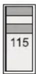
The following figure shows the basic curves of the generator with the phase relationships.
text_image
TTL-Pulse 0V Triangle 0V Sine 0V Rectangle 0V8.1.2 SETTING DC-OFFSET
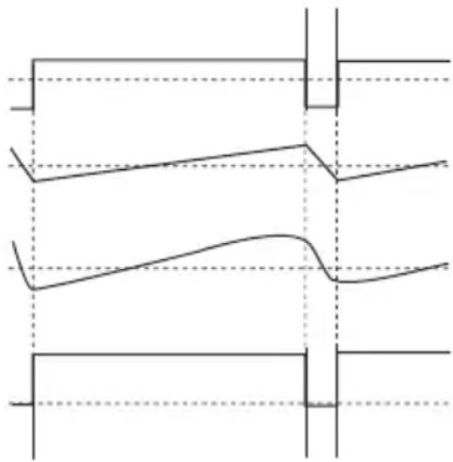
- The adjustment button "DC OFFSET" (11) permits changing the direct voltage share of the output signal in the area from approx. +/- 5 V at 50 Ohm (or +/- 10 V at the unloaded output). To set the offset, pull the adjustment button (11) to activate the function. A turn to the right (+) means a positive offset of the signal curve, a turn to the left (-) means a negative offset. If the adjustment button is pushed, the output signal has no direct voltage share.
The adjustment of the "DC OFFSET" up (positive) or down (negative) within the voltage limits (+/- 5 V at 50 Ohm or ± 10 V at the unloaded output) ensures that there is no danger of the amplitudes being cut off, which would lead to signal distortion. However, if a high amplitude and a great offset setting meet, the output signal may be distorted (cut). This can be verified easily with an oscilloscope. To avoid this problem, reduce the amplitude or the DC offset if possible.
The following table offers information on how and within which limits the offset level is moving and when the signal is cut (at 50 Ohm).
| Maximum amplitude settingNo DC-offsetNo distortion | 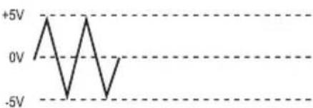 |
| Reduced amplitude settingLow DC-offsetNo distortion | 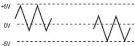 |
| Maximum amplitude settingLarge DC-offsetStrong distortion | 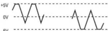 |
8.1.3 SETTING DC-OUTPUT
- The DC offset function can also be used to output a pure direct voltage without frequency overlay. Carefully push one of the unpushed switches in the field "FUNCTION" just until all three switches "jump" into the un-pushed position.
- If all three switches are not pushed, a pure direct voltage is pending at the output "OUTPUT". The pulled adjustment button "DC OFFSET" (11) can be used to set the DC level. Check the DC level with the DC voltage meter or using an oscilloscope.
8.1.4 SYMMETRY SETTING
• For this, also observe chapter 8.2.
- The output signal can be adjusted via the symmetry setting. The signal increase is changed, which leads to a symmetry offset. This leads to the generation of pulse tips in rectangles or a saw-tooth signal for triangle.
- To activate this function, pull the adjustment button "SYM" until it latches. In the middle position, the signal is symmetrical; a turn to the left shortens the rising flank; a turn to the right shortens the dropping flank. This function is off when the button is pushed.
8.1.5 SYNCHRONOUS OUTPUT TTL
- The synchronous unction outputs a TTL-rectangular signal with the signal frequency and symmetry independently of the wave shape of the output signal (except for DC). At the BNC-socket “OUTPUT TTL SYNC” (6), a TTL-level with fixed amplitude is pending. The frequency and symmetry of the TTL level are aligned with the basic signal. The operating elements “AMPL” (signal voltage), “DC OFF-SET” and “ATT” (dampener -20dB) do not influence the TTL-level.
8.2 "PULSE"-GENERATOR
The symmetry function “SYM” is used for application as pulse generator. For a standard signal such as sine, triangle or rectangle or TTL, the ratio between positive and negative half-wave is 1:1. By pulling the adjustment button “SYM” (12), the function “Symmetry setting” is activated, i.e. the ratio between positive and negative half-wave can be changed by more than 10:1 (in either direction!).
A sine signal then turns into an elongated sine, a triangular signal into a ramp or saw-tooth function and rectangle or TTL signal becomes a needle impulse.
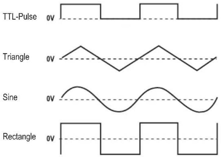
One example of how basic curves can change their appearance is shown in the following figure. The dashed line ---- corresponds to the zero line.
Pulse (from rectangle)
Ramp (of triangle)
Elongated sine
TTL-Pulse
natural_image
Pure electrical circuit lines without any symbolsTo change the symmetry of basic curves, proceed as follows:
- Set the function generator as described in chapter "7.4 Basic Setting" and connect output (7) to an oscilloscope. Always use a 50 Ohm end resistor to avoid signal distortions.
- Select the desired basic curve form by operating the corresponding switch in the field "FUNCTION". Push the switch for rectangular signals to receive needle impulses, the switch for triangular signals for ramps or saw-teeth or the switch for sine signals for an elongated sine.
- For extremely short increase times and long drop times (ratio up to and exceeding 1:10), pull the adjustment button "SYM" and turn it to the left (max. "Asymmetry" to the left stop). For extremely long increase and very short drop times, turn the adjustment button "SYM" to the right (max. "Asymmetry" to the right stop).
The symmetry adjustment changes the frequency and therefore should be re-adjusted.

Never exceed the max. input values, neither at the VCF-input nor at the frequency counter input, and avoid a short circuit at the generator outputs "TTL-OUT" and "OUTPUT". Otherwise, there is the danger of damage or even destruction of the frequency generator.
When the max. input values are exceeded or voltages above 50 VAC or 75 VDC are touched, there is the danger of a potentially fatal electric shock.
To better set the ratio at a ramp (triangle) or an elongated sine, we recommend pushing the switch for the rectangular signal "FUNCTION". Then determine the period duration of the drop and rise time at the oscilloscope and set them with the generator to the desired values (with adjustment button "SYM" and "FREQUENCY"). Then select the desired signal form.
8.3 TTL-SYNCHRONOUS OUTPUT
The TTL-output is intended for specific logic circuits. The TTL-level is fixed in its amplitude (voltage height). Frequency and symmetry are bound to the basic signal. A DC offset adjustment is not possible. The level is above the zero line.
Connect a shielded 50 Ohm-BNC-measuring line with alligator clamps at the TTL-output (6). Connect the red clamp (signal) to the cycle input of the logic circuit, the black terminal (ground) to the ground of the logic circuits.
The TTL-output can be used as "true" cycle generator for TTL-circuits. This output can be used to "drive" all TTL circuits.

Never exceed the max. input values, neither at the VCF-input nor at the frequency counter input, and avoid a short circuit at the generator outputs "TTL-SYNC" and "OUTPUT". Otherwise, there is the danger of damage or even destruction of the frequency generator.
When the max. input values are exceeded or voltages above 50 V/AC or 75 V/DC are touched, there is the danger of a potentially fatal electric shock.
8.4 FM SIGNAL GENERATOR
Frequency modulation (FM) is the change of the output frequency depending on the progress of a second infeed control frequency.
Proceed as follows to use the frequency generator as a frequency-modulated signal generator:
- Make the basic settings for the function generator as described in chapter 8.1. Set the carrier frequency with the adjustment button "FREQUENCY" and the amplitude with the adjustment button "AMPL".
- Apply a pure alternating voltage signal (modulation voltage without direct voltage share) to the VCF-input (5) via a BNC measuring line (HF-cable).
- Change the applied modulation voltage (max. 10 Vpp), until the desired frequency deviation is reached.
An approximate illustration of the interrelation between frequency modulation and the alternating voltage applied to the VCF input (modulation voltage) is described as follows:
A change to the alternating voltage at the VCF-input (VCF IN) by 0.1 V leads to a frequency change of 1 % of the maximum frequency setting possible (MAX-area of the adjustment button "FREQUENCY") of the respective frequency range set.
If, e.g., the switch "100k" is pushed in the filed "FREQUENCY RANGE (Hz)", the maximum frequency that can be achieved in this area is approx. 1 MHz. A change by 0.1 V corresponds to a frequency change by 10 kHz. In the following table, the interrelation between the set area or the max. frequency achieved and the frequency change per 0.1 V voltage change at the VCF-input is illustrated.
Example:
If a 455 kHz-signal is to be generated with a lift of +/-15 kHz (= 30 kHz-vibration), the switch "100k" in the field "FREQUENCY RANGE (Hz)" must be pushed at the frequency generator.
The adjustment button “FREQUENCY” sets the 455 kHz-carrier frequency. The maximum frequency that can be set in this frequency area is approx. 1 MHz.
1% of 1 MHz correspond to 10 kHz (= 0.1 V).
30 kHz is 3 times 10 kHz.
3 times 0.1 V therefore is 0.3 V.
| Frequency range in [Hz] Maximum | poss. frequency in [Hz] Frequency lift in [Hz] per 0.1V voltage change at VCF IN |
| 1 10 0,1 | |
| 10 100 1 | |
| 100 1 k 10 | |
| 1 k 10 k 100 | |
| 10 k 100 k 1 k | |
| 100 k 1 M 10 k | |
| 1 M 10 M 100 k |

Never exceed the max. input values, neither at the VCF-input nor at the frequency counter input, and avoid a short circuit at the generator outputs “TTL-SYNC” and “OUTPUT”. Otherwise, there is the danger of damage or even destruction of the frequency generator.
When the max. input values are exceeded or voltages above 50 V/AC or 75 V/DC are touched, there is the danger of a potentially fatal electric shock.
8.5 VOLTAGE-CONTROLLER FREQUENCY SETTING "VCF"
The generator's output frequency can be set by application of an external voltage up to 10 V in the form of a fixed or variable direct or alternating voltage.
The different voltage types are described in the following chapters.
By application of an external voltage in the range of 0 to 10 V at the VCF input (5), the output frequency can be changed at the ratio of up to 10:1. However, this depends on the respective position of the frequency range switch (13).
When applying an external direct voltage to the VCF socket, always observe polarity, “+” inside.
The output frequency is enlarged by application of a voltage. However, only the maximum frequency of the selected range can be set.
If, e.g., the range "1M" is set and the two adjustment buttons "FREQUENCY" are set to the "MIN" position while there is no voltage at the VCF input, the generator display shows approx. 100 kHz.
If you now apply a direct voltage to the VCF-input (5) and slowly adjust them up to 10 VDC, a frequency of approx. 10 MHz will finally be displayed at 10 VDC. An additional adjustment of the adjustment button "FREQUENCY" brings no further frequency increase.
| Control voltage VCF Range factor | |
| 0 0,1 | |
| 1 | 1 |
| 2 | 2 |
| 3 | 3 |
| 4 | 4 |
| 5 | 5 |
| 6 | 6 |
| 7 | 7 |
| 8 | 8 |
| 9 | 9 |
| 10 10 | |
Push the switch "1k" in the field "FREQUENCY RANGE" at the generator. Turn the adjustment button "FREQUENCY" until 5 kHz is displayed. By application of a voltage in the range from 0 to 10 V at the "VCF IN" input (5) only permits setting or enlargement of the frequency at the output (7) up to approx. 10 kHz.
Turn, e.g., the voltage at an adjustable mains unit slowly up to 10 V. The frequency at the generator output changes proportionally to the VCF-input voltage.
If the adjustment button "FREQUENCY" is already in the MAX area, only a very small voltage-controlled frequency change is possible.

Never exceed the max. input values, neither at the VCF-input nor at the frequency counter input, and avoid a short circuit at the generator outputs “TTL-SYNC” and “OUTPUT”. Otherwise, there is the danger of damage or even destruction of the frequency generator.
When the max. input values are exceeded or voltages above 50 V/AC or 75 V/DC are touched, there is the danger of a potentially fatal electric shock.
8.6 "PROGRAMMED" FREQUENCY SETTING
At the generator, pre-selected control voltages of 0 to 10 V permit “programming” specific frequencies. The control voltage is applied to the input “VCF IN”. The setting at the frequency generator is limited to a minimum.
Only adjust the desired frequency range and set the adjustment buttons "FREQUENCY" (16 and 18) to the position "MIN".
Apply a specific fixed direct voltage at the VCF input to receive the desired frequency at the generator output.
If several frequencies are needed within one frequency range, e.g. for test fields or quality assurance, different direct voltages can be applied via a level switch at the VCF-input.

Never exceed the max. input values, neither at the VCF-input nor at the frequency counter input, and avoid a short circuit at the generator outputs "TTL-SYNC" and "OUTPUT". Otherwise, there is the danger of damage or even destruction of the frequency generator.
When the max. input values are exceeded or voltages above 50 V/AC or 75 V/DC are touched, there is the danger of a potentially fatal electric shock.
8.7 WOBBULATOR (SWEEP)
The wobbulator permits linear frequency change at the signal output. The frequency range and the number of wobble sequences can be set.
To use the frequency generator as wobbulator, proceed as follows:
- Use the function generator as described in chapter 8.1.
- Push the desired area switch in the field "FREQUENCY RANGE (Hz)" (13), which the wobbulator is to run through.
- Set the frequency adjustment buttons (18 and 16) to the "MIN" position or the piston where the wobble process is to be started (e.g. 100Hz in the 1k-range).
- Pull the adjustment button "WIDTH" (14) until it latches; the wobble function is now active.
- The wobble speed (repeat rate) can be set via the adjustment button "RATE" (15).
- At the adjustment button "WIDTH" (14), the wobble bandwidth can be set within a selected frequency range.
- The display (2) shows a continuous change of the frequency. In case of quick wobble cycles, however, the display may not be able to show the actual frequency progress. This is due to the fixed gate time of the counter that does not change when the repeat rate (RATE) is set.
→ We recommend connecting an oscilloscope (if present) to monitor or review the settings.
8.8 EXTERNALLY CONTROLLER WOBBULATOR
The wobbulator can also be set via the VCF control input.
To use the function generator as voltage-controlled sweep generator, proceed as follows:
- Use the function generator as described in chapter 8.7. The adjustment button "WIDTH" remains pushed, however (do not pull). No setting is required at the adjustment button "RATE" or "WIDTH" either.
- Apply a direct-voltage free, asymmetrical change signal to the VCF-input (5). An amplitude of 0 to 10 V permits a wobble ratio up to 100:1. The curve shape is unimportant. Observe that the dropping flank of the signal is larger than the rising flank (changed symmetry).
→ We recommend connecting an oscilloscope (if present) to monitor or review the settings.

Never exceed the max. input values, neither at the VCF-input nor at the frequency counter input, and avoid a short circuit at the generator outputs "TTL-SYNC" and "OUTPUT". Otherwise, there is the danger of damage or even destruction of the frequency generator.
When the max. input values are exceeded or voltages above 50 V/AC or 75 V/DC are touched, there is the danger of a potentially fatal electric shock.
8.9 FREQUENCY COUNTER
The frequency generator can be used as frequency counter.
For this, switch the display to external counter operation via the switch "COUNTER INT/EXT" (17).
Switch pushed: External counter operation
Switch not pushed: Internal generator display
Select the frequency range "FREQUENCY RANGE 1" (13).
The counter input (4) is designated "EXT COUNT IN" and can be used for frequencies up to 100 MHz.
A “low-pass filter” is installed to be able to measure even lower frequencies (<100 kHz) without interferences. This suppresses high frequency shares (-3dB) that may falsify the measurement.
Push the switch "LPF" (17) during frequency measurement below 100 kHz. This switch must not be pushed at high frequencies.

The measuring signal must be galvanically separated from the mains. The amplitude must not exceed 48 Vpp (tip-tip). The input is protected against overload up to a signal voltage of 250 Vpp.
After application of a frequency of at least 2 Hz to max. 100 MHz with a signal voltage galvanically separated from the mains and a max. amplitude of 48 Vpp (= tip-tip), it is displayed on the 7-digit display. Other buttons for operation of the frequency counter are not required. The decimal point, the measuring units and the gate time are automatically set to the expected measuring signal. The input sensitivity is at least 100 mVrms.
The last measured frequency is retained in the display until a new measurable signal is recognised. When disconnecting the measuring line, the last measured value is retained until the function is changed or a new signal applied.

Never exceed the max. input values, neither at the VCF-input nor at the frequency counter input, and avoid a short circuit at the generator outputs “TTL-SYNC” and “OUTPUT”. Otherwise, there is the danger of damage or even destruction of the frequency generator.
When the max. input values are exceeded or voltages above 50 V/AC or 75 V/DC are touched, there is the danger of a potentially fatal electric shock.
9. MAINTENANCE AND CLEANING
Except for the fuse change and occasional cleaning, the function generator is maintenance-free. Use a clean, lint-free, antistatic and dry cloth to clean the device. Do not use any abrasive or chemical agents or detergents containing solvents.
Use a soft, clean and lint-free, anti-static and slightly moist cleaning cloth to clean the display.

Switch the function generator off before any cleaning or fuse change and disconnect all measuring lines. Also remove the mains line.
9.1 FUSE CHANGE
If it is no longer possible to switch on the device, the mains fuse is probably defective.
Proceed as follows to replace the mains fuse:
- Switch off the function generator and remove all measuring lines and the mains cable from the device.
- Unlock the rear fuse holder (22) counter-clockwise with a suitable flat screwdriver under slight pressure. The bayonet closure of the fuse holder unlocks. Take out the fuse holder.
- Replace the defective fuse with a new fine-wire fuse (5x20 mm) of the same type and rated current.
Different fuses are used, depending on mains voltage selection:
| Mains voltage Fuse | |
| 230 V 50/60 Hz F250 | mA / 250 V (quick-acting) |
| 115 V 50/60 Hz F500 | mA / 250 V (quick-acting) |
- Push the fuse insert back into the fuse holder and lock it under slight pressure clockwise until it latches cleanly.
10. DISPOSAL
Old electronic devices are raw materials and should not be disposed of in the household waste. At the end of its service life, dispose of the device at the community collection points according to the applicable statutory regulations.
It is prohibited to dispose of the device in the household waste.
You thus fulfil the legal requirements and make your contribution to protecting the environment!
11. TROUBLESHOOTING
By purchasing the function generator, you have acquired a product that is reliable and operationally safe.
Nevertheless, problems or errors may occur.
For this reason, we want to describe how you can easily remove possible malfunctions yourself below:

Always observe the safety information!
| Error Possible cause | |
| The device does not work.No display. | Poss. fuse in the device or line protection switch defective.Check the mains voltage. |
| No measurable output signal. Amplitude and dampener set incorrectly? | |
| No display change If the correct display source is selected (INT/EXT (17)) | |
| No symmetry setting,No offset setting,No wobble function possible. | The corresponding functions are not activated. |
Regularly check the technical safety of the device, e.g. for a damaged casing, etc.

Only qualified experts familiar with the hazards involved and the relevant regulations must perform any other repairs. Unauthorized modifications or repairs to the device will invalidate the warranty claim.
If you have any questions about handling the meter, our technical support is available.
12. TECHNICAL DATA
| Basic data | ||
| Frequency range 100 mHz to 10 MHz (+/- 3dB) Sine, rectangle, triangle | ||
| Frequency accuracy +/- 2% (of the measuring range) | ||
| Symbol 7-digit LED green | ||
| Output impedance 50 Ohm +/- 5% | ||
| Amplitude max. 20 Vpp (without closure) Rectangle: max. 17 Vpp | ||
| max. 10 Vpp (at 50 Ohm) Rectangle: max. 7.5 Vpp | ||
| Symmetry setting 1:1 to 10:1 at 100 kHz | ||
| VCF-input 0 - 10 V/DC/AC | ||
| Dampener -20dB | ||
| DC offset/output +/- 10V (without terminator) | ||
| +/- 5V (at 50 Ohm) | ||
| Total harmonic distortion, sine < 1% 10 Hz to 100 kHz | ||
| Rectangular signal Rise/drop time | <120ns | |
| Triangular signal | Linearity | >99% from 0.1 Hz to 100 kHz |
| TTL-output | Rise/drop time | <25 ns (at 1 MHz) |
| Level | High =/>2.4 V/Low =/<0.4V | |
| Wobble function | Mode | Linear |
| Bandwidth (Width) 1:1 to 100:1 | ||
| Wobble time (Rate) | 20 ms to 2 s (50 Hz to 0.5 Hz) | |
| Impedance | 1 kOhm | |
| Frequency counter | Frequency range 2 Hz - 100 MHz | |
| Accuracy | Time basis error +/- 1 Count | |
| Sensitivity 100 mVrms | ||
| Max. input voltage | 48 Vpp (17 Vrms) | |
| Overvoltage protection (max.) | 250 Vpp (88 Vrms) | |
| Time basis | 10 MHz, quartz oscillator +/-20 ppm | |
| Operating data | ||
| Operating voltage | 206 - 252 V/AC 50/60 Hz | Fuse: F250mA/250V (quick-acting) |
| 103 - 126 V/AC 50/60 Hz | Fuse: F500mA/250V (quick-acting) | |
| Power consumption | 20 W | |
| Measuring category | CAT II 250 V | |
| Degree of contamination | 2 | |
| Operating temperature | 0°C to 40°C (operation) | -20°C to 70°C (storage) |
| Relative humidity max. 85%, non-condensing | ||
| Accuracy information referring to 23 °C ± 5 °C Heating time at least 30 minutes | ||
| Dimensions (W x H x D) 240 x 90 x 270 (mm) | ||
| Weight Approx. 3 kg | ||
Cher client,
mHz millihertz (exp. -3)
kHz kilohertz (exp. 3)
natural_image
Pure electrical circuit lines without any symbolsnatural_image
Pure electrical circuit lines without any symbols© Copyright 2013 by Conrad Electronic SE.

Legal Notice
These operating instructions are a publication by Conrad Electronic SE, Klaus-Conrad-Str. 1, D-92240 Hirschau (www.conrad.com).
All rights including translation reserved. Reproduction by any method, e.g. photocopy, microfilming, or the capture in electronic data processing systems require the prior written approval by the editor. Reprinting, also in part, is prohibited.
These operating instructions represent the technical status at the time of printing. Changes in technology and equipment reserved.
© Copyright 2013 by Conrad Electronic SE.

Information légales
© Copyright 2013 by Conrad Electronic SE.

Colofon
© Copyright 2013 by Conrad Electronic SE. V2_1113_01/AB