
272320 - Electric saw MILWAUKEE - Free user manual and instructions
Find the device manual for free 272320 MILWAUKEE in PDF.
| Product Type | Electric Router (Router) |
| Brand | Milwaukee |
| Model | 2723-20 |
| Voltage | 18 V DC |
| Battery Type | M18™ |
| No-Load Speed | 10,000 – 31,000 RPM |
| Maximum Bit Diameter | 38 mm (1-1/2 in) |
| Collet Size | 1/4 in |
| Operating Temperature | -18°C to 50°C (0°F to 125°F) |
| Included Base | Fixed base (31-06-0036) + plunge and offset bases optional |
| Speed Control | Variable dial (6 positions) |
| Electronic Protection | Overload protection and constant speed maintenance |
| Spindle Lock | Yes, for bit changes |
| LED Light | Yes, integrated LED indicator |
| Dust Extraction Connection | Yes, adaptable to bases |
| Straight Edge Guide | Included for straight cuts |
| Template Guide | Max. 30 mm (1-3/16 in) |
| Warranty | 5 years (tool), 2-3 years for accessories (see manual) |
Frequently Asked Questions - 272320 MILWAUKEE
User questions about 272320 MILWAUKEE
0 question about this device. Answer the ones you know or ask your own.
Ask a new question about this device
Download the instructions for your Electric saw in PDF format for free! Find your manual 272320 - MILWAUKEE and take your electronic device back in hand. On this page are published all the documents necessary for the use of your device. 272320 by MILWAUKEE.
USER MANUAL 272320 MILWAUKEE
natural_image
Line drawing of a Milwaukee coffee maker with visible caliper and branding (no text or symbols on the device itself)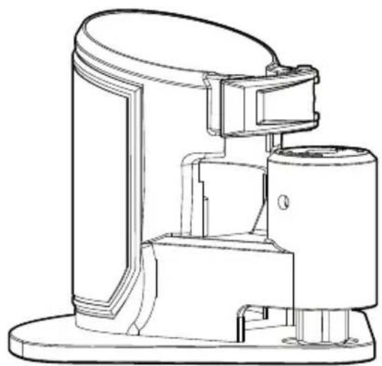
natural_image
Technical line drawing of a mechanical device with no visible text or symbols
natural_image
Technical line drawing of a mechanical device with dual levers and a central scale (no text or symbols)Cat. No. / No de cat. 2723-20, 48-10-5601, 48-10-5602
M18 FUEL™ COMPACT ROUTER TOUPIE COMPACTE M18 FUEL™ REBAJADORA COMPACTA M18 FUEL™

WARNING To reduce the risk of injury, user must read and understand operator's manual.
⚠ WARNING Read all safety warnings, instructions, illustrations and specifica-
tions provided with this power tool. Failure to follow all instructions listed below may result in electric shock, fire and/or serious injury. Save all warnings and instructions for future reference. The term "power tool" in the warnings refers to your mains-operated (corded) power tool or battery-operated (cordless) power tool.
WORK AREA SAFETY
- Keep work area clean and well lit. Cluttered or dark areas invite accidents.
- Do not operate power tools in explosive atmospheres, such as in the presence of flammable liquids, gases or dust. Power tools create sparks which may ignite the dust or fumes.
- Keep children and bystanders away while operating a power tool. Distractions can cause you to lose control.
ELECTRICAL SAFETY
- Power tool plugs must match the outlet. Never modify the plug in any way. Do not use any adapter plugs with earthed (grounded) power tools. Unmodified plugs and matching outlets will reduce risk of electric shock.
- Avoid body contact with earthed or grounded surfaces, such as pipes, radiators, ranges and refrigerators. There is an increased risk of electric shock if your body is earthed or grounded.
- Do not expose power tools to rain or wet conditions. Water entering a power tool will increase the risk of electric shock.
- Do not abuse the cord. Never use the cord for carrying, pulling or unplugging the power tool. Keep cord away from heat, oil, sharp edges or moving parts. Damaged or entangled cords increase the risk of electric shock.
- When operating a power tool outdoors, use an extension cord suitable for outdoor use. Use of a cord suitable for outdoor use reduces the risk of electric shock.
- If operating a power tool in a damp location is unavoidable, use a ground fault circuit interrupter (GFCI) protected supply. Use of an GFCI reduces the risk of electric shock.
PERSONAL SAFETY
- Stay alert, watch what you are doing and use common sense when operating a power tool. Do not use a power tool while you are tired or under the influence of drugs, alcohol or medication. A moment of inattention while operating power tools may result in serious personal injury.
- Use personal protective equipment. Always wear eye protection. Protective equipment such as a dust mask, non-skid safety shoes, hard hat or hearing protection used for appropriate conditions will reduce personal injuries.
-
Prevent unintentional starting. Ensure the switch is in the off-position before connecting to power source and/or battery pack, picking up or carrying the tool. Carrying power tools with your finger on the switch or energizing power tools that have the switch on invites accidents.
-
Remove any adjusting key or wrench before turning the power tool on. A wrench or a key left attached to a rotating part of the power tool may result in personal injury.
- Do not overreach. Keep proper footing and balance at all times. This enables better control of the power tool in unexpected situations.
- Dress properly. Do not wear loose clothing or jewelry. Keep your hair and clothing away from moving parts. Loose clothes, jewelry or long hair can be caught in moving parts.
- If devices are provided for the connection of dust extraction and collection facilities, ensure these are connected and properly used. Use of dust collection can reduce dust-related hazards.
- Do not let familiarity gained from frequent use of tools allow you to become complacent and ignore tool safety principles. A careless action can cause severe injury within a fraction of a second.
POWER TOOL USE AND CARE
- Do not force the power tool. Use the correct power tool for your application. The correct power tool will do the job better and safer at the rate for which it was designed.
- Do not use the power tool if the switch does not turn it on and off. Any power tool that cannot be controlled with the switch is dangerous and must be repaired.
- Disconnect the plug from the power source and/or remove the battery pack, if detachable, from the power tool before making any adjustments, changing accessories, or storing power tools. Such preventive safety measures reduce the risk of starting the power tool accidentally.
- Store idle power tools out of the reach of children and do not allow persons unfamiliar with the power tool or these instructions to operate the power tool. Power tools are dangerous in the hands of untrained users.
- Maintain power tools and accessories. Check for misalignment or binding of moving parts, breakage of parts and any other condition that may affect the power tool's operation. If damaged, have the power tool repaired before use. Many accidents are caused by poorly maintained power tools.
- Keep cutting tools sharp and clean. Properly maintained cutting tools with sharp cutting edges are less likely to bind and are easier to control.
- Use the power tool, accessories and tool bits etc. in accordance with these instructions, taking into account the working conditions and the work to be performed. Use of the power tool for operations different from those intended could result in a hazardous situation.
- Keep handles and grasping surfaces dry, clean, and free from oil and grease. Slippery handles and grasping surfaces do not allow for safe handling and control of the tool in unexpected situations.
BATTERY TOOL USE AND CARE
- Recharge only with the charger specified by the manufacturer. A charger that is suitable for one type of battery pack may create a risk of fire when used with another battery pack.
- Use power tools only with specifically designated battery packs. Use of any other battery packs may create a risk of injury and fire.
- When battery pack is not in use, keep it away from other metal objects, like paper clips, coins, keys, nails, screws or other small metal objects, that can make a connection from one terminal to another. Shorting the battery terminals together may cause burns or a fire.
- Under abusive conditions, liquid may be ejected from the battery; avoid contact. If contact accidentally occurs, flush with water. If liquid contacts eyes, additionally seek medical help. Liquid ejected from the battery may cause irritation or burns.
- Do not use a battery pack or tool that is damaged or modified. Damaged or modified batteries may exhibit unpredictable behavior resulting in fire, explosion or risk of injury.
- Do not expose a battery pack or tool to fire or excessive temperature. Exposure to fire or temperature above 265^ (130°C) may cause explosion
- Follow all charging instructions and do not charge the battery pack or tool outside the temperature range specified in the instructions. Charging improperly or at temperatures outside the specified range may damage the battery and increase the risk of fire.
SERVICE
- Have your power tool serviced by a qualified repair person using only identical replacement parts. This will ensure that the safety of the power tool is maintained.
- Never service damaged battery packs. Service of battery packs should only be performed by the manufacturer or authorized service providers.
SPECIFIC SAFETY RULES FOR COMPACT ROUTERS
- Use clamps or another practical way to secure and support the workpiece to a stable platform. Holding the work by your hand or against the body leaves it unstable and may lead to loss of control.
- Always hold the tool firmly in your hand(s) during the start-up. The reaction torque of the motor, as it accelerates to full speed, can cause the tool to twist.
- Maintain a firm grip on the power tool and position your body and arm to allow you to resist kickback forces. The operator can control kickback forces, if proper precautions are taken.
- Some woods contain preservatives that can be toxic. Take extra care to prevent inhalation and skin contact when working with these materials. Request, and follow, any safety information available from your material supplier.
- Never hold the workpiece in one hand and the tool in the other hand when using the tool. Never place hands near or below cutting surface. Clamping the material and guiding the tool with both hands is safer.
- Never use dull or damaged bits. Sharp bits must be handled with care. Damaged bits can break during use. Dull bits require more force to push the tool, which could cause the bit to break. Damaged bits can throw carbide pieces and burn the workpiece.
- After changing the bit or making any adjustments, make sure the collet nut and any other adjustment devices are securely tightened. Loose adjustment devices can unexpectedly shift, causing loss of control. Loose rotating components will be violently thrown. Watch for vibration or wobbling that could indicate an improperly installed bit.
- Never start the tool when the bit is in contact with the material. The bit cutting edge may grab the material causing loss of control of the tool.
- Never lay the tool down until the bit has come to a complete stop. The spinning bit can grab the surface and pull the tool out of your control.
- Never touch the bit during or immediately after use. After use the bit, collet, and collet nut may be hot enough to burn bare skin.
- Never clamp the workpiece to a hard surface, such as concrete or stone. Contact with the bit could cause the tool to jump and loss of control.
- Only operate the routers when held. Do not clamp or secure the router to a surface and hold the workpiece by hand.
- Never use bits larger than the smallest of the openings in the base, sub-base, or dust collection port.
- Do not loosen or remove the plunge base caps. Internal springs are under pressure. If loosened or removed, the plunge base caps and internal springs will become projectiles, which could cause injury.
WARNING To reduce the risk of injury, when working in dusty situations, wear appropriate respiratory protection or use an OSHA compliant dust extraction solution.
- Always use common sense and be cautious when using tools. It is not possible to anticipate every situation that could result in a dangerous outcome. Do not use this tool if you do not understand these operating instructions or you feel the work is beyond your capability; contact Milwaukee Tool or a trained professional for additional information or training.
- Maintain labels and nameplates. These carry important information. If unreadable or missing, contact a MILWAUKEE service facility for a free replacement.
WARNING Some dust created by power sanding, sawing, grinding, drilling, and other construction activities contains chemicals known to cause cancer, birth defects or other reproductive harm. Some examples of these chemicals are:
- lead from lead-based paint
• crystalline silica from bricks and cement and other masonry products, and
• arsenic and chromium from chemically-treated lumber.
Your risk from these exposures varies, depending on how often you do this type of work. To reduce your exposure to these chemicals: work in a well ventilated area, and work with approved safety equipment, such as those dust masks that are specially designed to filter out microscopic particles.
SPECIFICATIONS
Cat. No....2723-20*
Volts 18 DC
Battery Type ......M18™
Charger Type......M18™
No Load RPM 10,000 - 31,000
Maximum Bit Size 1-1/2"
Collet Size 1/4"
Recommended Ambient
Operating Temperature 0°F to 125°F
Plunge Base Cat. No. 48-10-5601
Offset Base Cat. No. 48-10-5602
*Comes with Fixed Base 31-06-0036
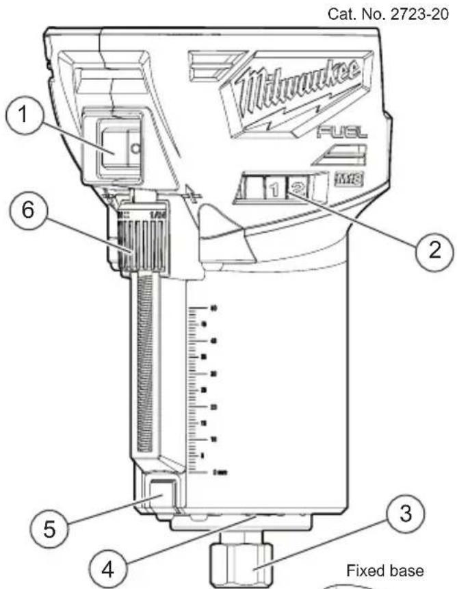
-
ON/OFF switch
-
Speed control dial
-
Collet / collet nut
-
LED (not shown)
-
Spindle lock
-
Micro adjustment dial
-
Quick release 14 lever
-
Macro adjustment button
-
Gripping surface
-
Depth turret
-
Micro adjustment sleeve
-
Handles
-
Depth gauge knob
-
Plunge release lever
-
Depth gauge indicator
-
Depth gauge
-
Shaft / housing hole
SYMBOLOGY


Direct Current
n_0 XXXX min ^-1 No Load Revolutions per Minute (RPM)

Read Operator's Manual

UL Listing for Canada and U.S.
AWARNING Recharge only with the charger specified for the battery. For specific charging instructions, read the operator's manual supplied with your charger and battery.
Removing/Inserting the Battery
To remove the battery, push in the release buttons and pull the battery pack away from the tool.
WARNING Always remove battery pack before changing or removing accessories.
To insert the battery, slide the pack into the body of the tool. Make sure it latches securely into place.
AWARNING Only use accessories specifically recommended for this tool. Others may be hazardous.
Always remove battery from tool before changing or removing accessories. Only use accessories specifically recommended for this tool. Others may be hazardous.
Installing Collets
The collet must be attached to the collet nut before installing the collet assembly to the tool. Be sure that the collet size matches the size of the bit shank, otherwise the collet may break.
-
To assemble, place collet on an even surface, and place the nut over the collet.
-
Press down on the nut to snap the nut and collet together.
-
To disassemble, use a rod to push the collet out of the nut.
Installing/Removing Bits
⚠ WARNING Always remove battery from the tool before attaching or removing accessories or making adjustments.
Use only specifically recommended accessories. Others may be hazardous.
Never use bits larger than the smallest of the openings in the base, sub-base, or dust shroud. The use of larger bits can result in loss of control and possible serious personal injury.
Do not tighten the collet nut without inserting the bit. The collet may break.
Never touch the bit during or immediately after use. After use the bit, collet, and collet nut may be hot enough to burn bare skin.
-
Turn the On/Off switch to OFF (O) and remove the battery pack.
-
Place the router upside down on a workbench.
-
Press and hold the spindle lock and use the 11/16" wrench to loosen the collet nut counterclockwise (or use the 7/16" spindle lock wrench to hold the spindle securely).
-
Insert the bit shank into the collet as far as it will go.
-
Back the bit shank out slightly to avoid bottoming out.
-
Be sure there is a minimum of 1/16" between the bottom of the collet assembly and the radius to the cutting portion of the bit.
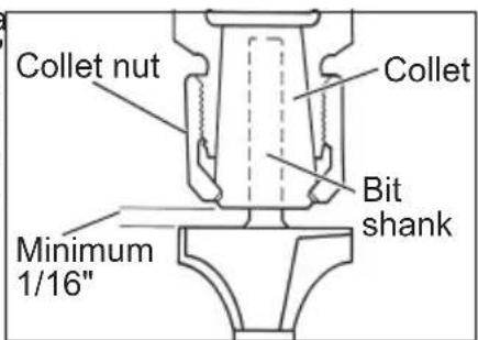
- Be sure that the collet is not clamped to a fluted section on the bit shank. The collet should be clamped to a solid part on the bit shank to ensure a tight grip.
- Hand-tighten the collet nut.
- Press and hold the spindle lock and use the 11/16" wrench to securely tighten the collet nut clockwise (or use the 7/16" spindle lock wrench to hold the spindle securely).
⚠ WARNING If the collet nut is not tightened securely, the bit may come out during use, causing serious personal injury.
Installing/Removing Bases
⚠ WARNING To reduce the risk of injury, DO NOT use the router if the quick release lever does not hold the motor securely in the base. If the quick release lever becomes loose, secure the screw with a 3 mm hex wrench to make a snug fit.
Pressing the macro adjustment button will cause the motor housing to drop down, which may cause personal injury or damage to the tool or workpiece. Make sure your hand is firmly on the motor when pressing the button.
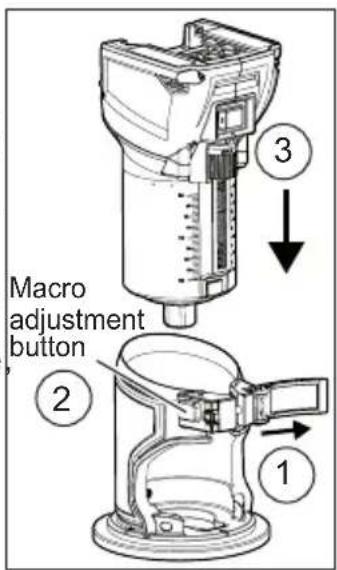
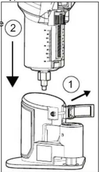
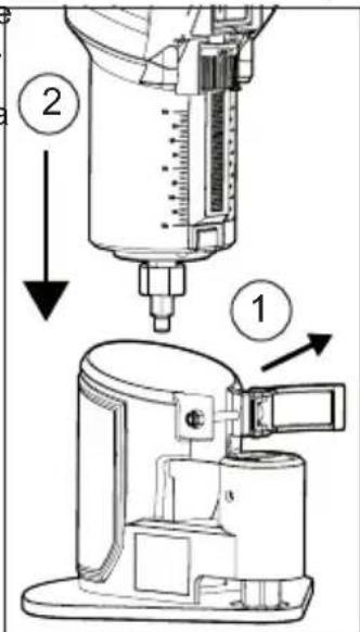
Fixed Base
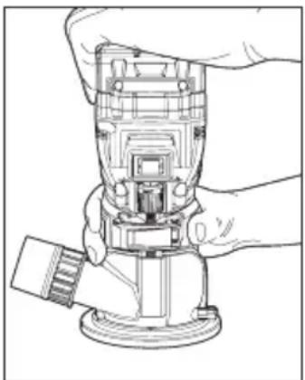
- Open the quick release lever. (1)
- Press the macro adjustment button on the fixed base. (2)
- Insert the tool into the base. (3)
- Release the button.
- Close the quick release lever.
- To remove the base reverse the procedure.
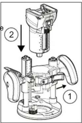
Accessory Plunge Base
- Open the quick release lever. (1)
- Insert the tool into the base. (2)
- Close the quick release lever.
- To remove the base, reverse the procedure.
Accessory Offset Base
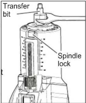
To install the offset base, the collet assembly must be removed from the router motor and installed onto the offset base. The transfer bit must be installed onto the router motor.
- Press and hold the spindle lock and use the 11/16" wrench to loosen the collet nut counterclockwise (or use the 7/16" spindle lock wrench to hold the spindle securely).
- Remove the collet nut and install the transfer bit.
- Press and hold the spindle lock and use the 11/16" wrench to secure clockwise (or use the 7/1 to hold the spindle secur
- Open the quick release lever. (1)
- Insert the tool into the base. (2)
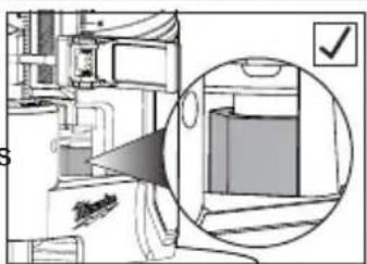
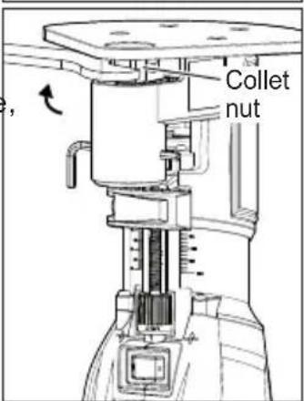
- Visually confirm that the transfer bit is seated inside the pulley connection in the offset base.
- If the transfer bit does not align, remove the motor from the offset base, rotate the transfer bit slightly, and reinstall the base.
- Close the quick release lever.
- Thread the collet nut assembly into the offset base.
-
Insert the router bit into the collet until it bottoms
-
To set the depth of cut, insert the 3 mm hex wrench into the micro adjustment set screw. Rotate clockwise (-) or counterclockwise (+) to reach the desired depth of cut.
natural_image
Interior view of a kitchen or office space with a close-up inset showing a cabinet and a checkmark (no text or symbols present)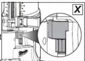
natural_image
Technical diagram of a mechanical assembly with an inset close-up showing a component (no visible text or symbols)- Rotate the collet nut to align the output shaft hole with the housing hole. Insert the 3 mm hex wrench through both the output shaft and housing.

-
Use the 11/16" wrench to securely tighten the collet nut clockwise.
-
To remove the base, reverse the procedure.
⚠ WARNING During use, always keep vacuum hose clear of the path of the bit. Installing a Dust Shroud
Fixed Base
-
Attach the dust shrouc to the fixed base, and tighten the thumb screw.
-
Connect a vacuum hose to the port.
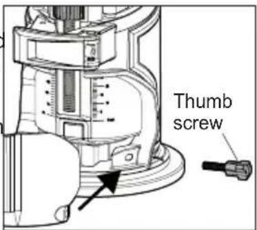
⚠ WARNING To reduce the risk of injury, do not use the dust shroud when plunge cutting if the bit is larger than the port opening (1-3/8"). If a rotating router bit contacts the dust shroud, the adapter will break and flying debris may cause injury.
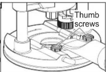
Accessory Plunge Base
-
Attach the dust shroud to the plunge base, and slide the U-rod into the base holes.
-
Tighten the thumb screws.
-
Connect a vacuum hose to the port.
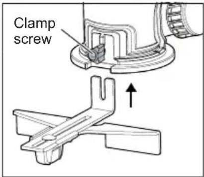
Installing a Straight Edge Guide
The straight edge guide is for use with the fixed base.
- Assemble the straight edge guide, as shown.
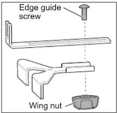
- Attach the straight edge guide to the fixed base and tighten the clamp screw securely.
Template Guides
Use only a maximum 1-3/16" template guide with this tool. A 5-3/4" template sub-base plate is needed to install a template guide. Always use a centering cone for best results with a 1-3/16" center hole.
To install a template guide, insert the guide into the center hole of the subbase and secure according to the template guide instructions.
OPERATION
AWARNING To reduce the risk of injury, always wear proper eye protection marked to comply with ANSI Z87.1.
When working in dusty situations, wear appropriate respiratory protection or use an OSHA compliant dust extraction solution.
Remove the battery before changing accessories or making adjustments.
Never make adjustments while the router is running.
DO NOT use the router if the quick release lever does not hold the motor securely in the base.
NEVER use the plunge base in a router table.
Selecting the Speed
The (RPM) of tool can be changed by turning the speed control dial. Variable speed dial settings range from numbers six (6) through one (1). Higher numbers correspond to higher speeds and lower number correspond to lower speeds.
Use higher speeds for smaller bits and cutters, softwoods, plastics and laminates.
Use lower speeds for larger diameter bits and cutters.
Feedback Control
The electronic speed control system allows the tool to maintain constant speed between no-load and load conditions.
Electronic Overload Protection
These tools are equipped with an electronic overload protection feature. If the motor shuts off during use, remove the bit from the workpiece and push the On/Off switch to the OFF (O) position to reset the tool. Allow the tool to cool before restarting your work
WARNING
Pressing the macro adjustment button will cause the motor hous-
ing to drop down, which may cause personal injury or damage to the tool or workpiece. Make sure your hand is firmly on the motor when pressing the button.
Adjusting the Cutting Depth
Fixed Base
Changes to cutter depth can be read on the depth scale on the motor housing. Each mark on the scale indicates a 1/16" change in depth setting. Use the bottom edge of the removable base as reference when setting depth of cut. To make deeper cuts, make successive passes as required, lowering the bit 1/8" for each pass.
- Turn the On/Off switch to OFF (O) and remove the battery pack.
- Open the quick release lever.
- Press the macro adjustment button and slide the motor close to the desired depth.
- Use the micro adjustment dial to fine-adjust to the desired depth of cut.
- Close the quick release lever.
Accessory Plunge Base
The plunge base depth of cut can be set two ways; for single pass cuts (shallow cuts less than 1/8"), or for multiple pass cuts.
Single Pass Cuts
A shallow cut, such as a mortis cut, can be cut in a single pass.
- Turn the On/Off switch to OFF (O) and remove the battery pack.
- Install the bit and insert the tool into the base.
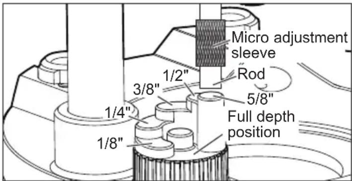
- Rotate the depth turret until the highest setting (5/8") is directly below the depth gauge rod.
- Loosen the depth gauge knob.
- Press the plunge release lever and lower the router motor until the bit touches the workpiece.
- Release the plunge release lever.
- Set the depth of cut:
a. Raise the depth gauge rod and slide the piece to be inlaid (such as a hinge) between the top turret and the depth gauge rod. Tighten the depth gauge knob. Remove the reference piece from the turret.
b. Slide the depth gauge indicator to zero (0) and then raise the depth gauge rod to the desired depth of cut. Tighten the depth gauge knob. NOTE: do not exceed 1/8" cut in a single pass.
- Make the cut as described in Making the Cut - Accessory Plunge Base.
Multiple Pass Cuts
For cuts more than 1/8" deep, multiple passes are necessary.
- Turn the On/Off switch to OFF (O) and remove the battery pack.
- Install the bit and insert the tool into the base.
- Rotate the depth turret until the lowest setting (full depth position) is directly below the depth gauge rod.
- Loosen the depth gauge knob.
- Press the plunge release lever and lower the router motor until the bit touches the workpiece.
- Slide the depth gauge indicator to zero (0).
- Raise the depth gauge rod to the desired depth of cut.
- Tighten the depth gauge knob.
- Use the micro adjustment sleeve for fine adjustments (loosen for a shallower cut, tighten for a deeper cut).
- Press the plunge release lever and raise the router motor.
- Rotate the turret to the highest possible step to prepare for the first cut.
- Make the cut as described in Making the Cut - Accessory Plunge Base.
Accessory Offset Base
The depth of cut of the offset bit is set when the bit is installed.
WARNING
Holding the Tool
Keep hands and body away from the bit and all moving parts.
Always hold the tool firmly in your hand(s) during the start-up. The reaction torque of the motor, as it accelerates to full speed, can cause the tool to twist.
Maintain a firm grip on the power tool and position your body and arm to allow you to resist kickback forces. The operator can control kickback forces, if proper precautions are taken.
Fixed Base and Accessory Offset Base
For best results, hold tool with one hand on the base and a second hand on the top of the battery pack.
natural_image
Line drawing of a hand operating a mechanical device with a handle (no text or symbols)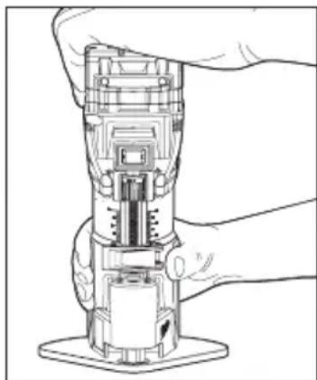
natural_image
Line drawing of a robotic arm gripping a mechanical component (no text or symbols)Accessory Plunge Base
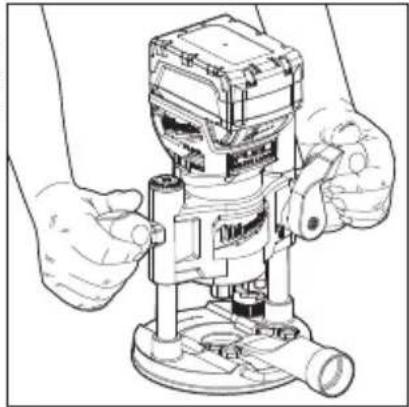
⚠ WARNING To reduce the risk of injury, NEVER use the plunge base in a router
table.
Hold tool with both hands on the handles at all times for maximum control.
natural_image
Line drawing of a mechanical presser with hands operating it (no text or symbols present)WARNING To reduce the risk of injury, always wear eye protection.
To reduce the risk of explosion, electric shock and property damage, always check the work area for hidden pipes and wires before routing.
Avoid open area of router base. Serious personal injury will result from contact with a rotating bit.
Starting and Stopping the Router Motor
- To start the motor, hold the router so the bit is away from you and not in contact with the workpiece.
- Hold the tool firmly and turn the On/Off switch to ON (I).
- To stop the motor, hold the router so the bit is away from you and turn the On/Off switch to OFF (O). Hold the tool until the bit stops turning.
Making the Cut
Before cutting, check that the collet nut and all adjustments are tight. Verify that the quick release lever is fully closed and secure.
Set the speed and depth of cut for material being worked. Keep the cutting pressure constant but do not use excessive force on the router so the motor speed slows excessively. It may be necessary on exceptionally hard woods, problem materials, or extreme cuts to make more than one pass to get the desired depth of cut.
When using the dust collection hose, place the hose out of the path of the router.
Before beginning the cut on the workpiece, make a sample cut on a scrap piece of lumber to check the settings and dimensions. Always be sure the workpiece is secure before routing. When routing edges, the router should be held firmly down and against the work.
Since the cutter rotates clockwise, more efficient cutting will be obtained if the router is moved from left to right as you stand facing the work. The arrows on the base of the tool indicate the direction of bit rotation. When working on the outside of an edge, move router in a counterclockwise direction.
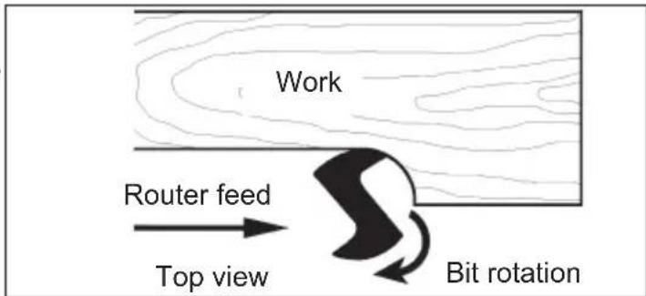
When working on an inside edge, move the router in a clockwise direction.
Moving the router in the opposite direction is known as "climb cutting."
⚠ WARNING To reduce the risk of injury, avoid "climb cutting." Climb cutting increases the potential for loss of control of the tool and damage to the workpiece. If climb cutting can not be avoided, use extreme caution.
Fixed Base with a Straight Edge
To obtain a straight cut, use the straight edge guide, or clamp a piece of scrap lumber to use as a guide.
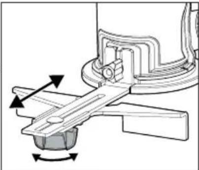
- To adjust the straight edge guide, loosen the wing nut and adjust the distance between the bit and the straight edge guide. Tighten the wing nut securely.
natural_image
Mechanical assembly diagram showing a lever mechanism with rotational arrows (no text or labels)- To use the straight edge guide, move the tool with the straight edge guide flush with the side of the workpiece.
natural_image
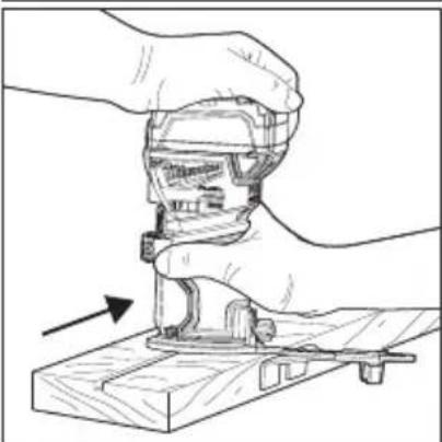
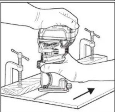
Illustration of hands using a mechanical tool to adjust or install a component on a wooden base (no text or symbols)- To use a piece of scrap lumber as a guide, when the distance between the side of the workpiece and the cutting position is too wide for the straight edge guide, or if the side of the workpiece is not straight. Securely clamp a
natural_image
Illustration of hands operating a mechanical clamp or vise with a wooden base, showing no text or symbols.straight board to the work-piece and use it as a guide against the trimmer base.
Accessory Plunge Base
AWARNING Always hold the handles firmly with both hands during operation.
Do not use a plunge base router if the motor does not rise automatically when the plunge release lever is pressed.
NEVER use the plunge base in a router table.
- Securely clamp the workpiece.
- Set the depth of cut as described in Adjusting the Cutting Depth - Accessory Plunge Base.
- Press the plunge release lever and raise the bit above the workpiece.
- Hold the router so the bit is away from you and not in contact with the workpiece. Turn on the tool.
- Press the plunge release lever and slowly lower the bit into the workpiece until the depth stop rod contacts the turret. Release the plunge release lever.
- Begin moving the router, keeping the sub base flat on the workpiece.
- When finished, press the plunge release lever and raise the bit out of the workpiece.
- To stop the motor, hold the router so the bit is away from you and turn the On/Off switch to OFF (O).
- For multiple pass cuts, rotate the turret to the next step and repeat. Make multiple passes, rotating the turret to a lower step each time.
MAINTENANCE
⚠ WARNING To reduce the risk of injury, always unplug the charger and remove the battery pack from the charger or tool before performing any maintenance. Never disassemble the tool, battery pack or charger. Contact a MILWAUKEE service facility for ALL repairs.
Maintaining Tool
Keep your tool, battery pack and charger in good repair by adopting a regular maintenance program. Inspect your tool for issues such as undue noise, misalignment or binding of moving parts, breakage of parts, or any other condition that may affect the tool operation. Return the tool, battery pack, and charger to a MILWAUKEE service facility for repair. After six months to one year, depending on use, return the tool, battery pack and charger to a MILWAUKEE service facility for inspection. If the tool does not start or operate at full power with a fully charged battery pack, clean the contacts on the battery pack. If the tool still does not work properly, return the tool, charger and battery pack, to a MILWAUKEE service facility for repairs.
WARNING To reduce the risk of personal injury and damage, never immerse your tool, battery pack or charger in liquid allow a liquid to flow inside them.
Cleaning
Clean dust and debris from vents. Keep handles clean, dry and free of oil or grease. Use only mild soap and a damp cloth to clean, since certain cleaning agents and solvents are harmful to plastics and other insulated parts. Some of these include gasoline, turpentine, lacquer thinner, paint thinner, chlorinated cleaning solvents, ammonia and household detergents containing ammonia. Never use flammable or combustible solvents around tools.
Repairs
For repairs, return the tool, battery pack and charger to the nearest service center.
ACCESSORIES
WARNING Use only recommended accessories. Others may be hazardous.
For a complete listing of accessories, go online to www.milwaukeeetool.com or contact a distributor.
SERVICE - UNITED STATES
1-800-SAWDUST (1.800.729.3878)
Monday-Friday, 7:00 AM - 6:30 PM CST
or visit www.milwaukeetool.com
Contact Corporate After Sales Service Technical Support with technical, service/repair, or warranty questions.
Email: metproductsupport@milwaukeeetool.com
Become a Heavy Duty Club Member at www.milwaukeetool.com to receive important notifications regarding your tool purchases.
SERVICE - CANADA
Milwaukee Tool (Canada) Ltd 1.800.268.4015
Monday-Friday, 7:00 AM - 4:30 PM CST
or visit www.milwaukeetool.ca
LIMITED WARRANTY USA & CANADA
Every MILWAUKEE power tool* (see exceptions below) is warranted to the original purchaser only to be free from defects in material and workmanship. Subject to certain exceptions, MILWAUKEE will repair or replace any part on an electric power tool which, after examination, is determined by MILWAUKEE to be defective in material or workmanship for a period of five (5) years** after the date of purchase unless otherwise noted. Return of the power tool to a MILWAUKEE factory Service Center location or MILWAUKEE Authorized Service Station, freight prepaid and insured, is required. A copy of the proof of purchase should be included with the return product. This warranty does not apply to damage that MILWAUKEE determines to be from repairs made or attempted by anyone other than MILWAUKEE authorized personnel, misuse, alterations, abuse, normal wear and tear, lack of maintenance, or accidents. Normal Wear: Many power tools need periodic parts replacement and service to achieve best performance. This warranty does not cover repair when normal use has exhausted the life of a part including, but not limited to, chucks, brushes, cords, saw shoes, blade clamps, o-rings, seals, bumpers, driver blades, pistons, strikers, lifters, and bumper cover washers. *This warranty does not cover Air Nailers & Staplers; Airless Paint Sprayer; Cordless Battery Packs; Gasoline Driven Portable Power Generators; Hand Tools; Hoist – Electric, Lever & Hand Chain; M12™ Heated Gear; Reconditioned Product; and Test & Measurement Products. There are separate and distinct warranties available for these products. **The warranty period for Job Site Radios, M12™ Power Port, M18™ Power Source, Jobsite Fan and Trade Titan™ Industrial Work Carts is one (1) year from the date of purchase. The warranty period for the Drain Cleaning Cables and AIRSNAKETM Drain Cleaning Air Gun Accessories is two (2) years from the date of purchase. The warranty period for the M18™ Compact Heat Gun, 8 Gallon Dust Extractor, M18™ Framing Nailers, and the M18 FUEL™ 1/2" Ext. Anvil Controlled Torque Impact Wrench w/ ONE-KEY™ is three (3) years from the date of purchase. The warranty period for the LED in the LED Work Light and the LED Upgrade Bulb for the Work Light is the lifetime of the product subject to the limitations above. If during normal use the LED or LED Bulb fails, the part will be replaced free of charge. Warranty Registration is not necessary to obtain the applicable warranty on a MILWAUKEE power tool product. The manufacturing date of the product will be used to determine the warranty period if no proof of purchase is provided at the time warranty service is requested. ACCEPTANCE OF THE EXCLUSIVE REPAIR AND REPLACEMENT REMEDIES DESCRIBED HEREIN IS A CONDITION OF THE CONTRACT FOR THE PURCHASE OF EVERY MILWAUKEE PRODUCT. IF YOU DO NOT AGREE TO THIS CONDITION, YOU SHOULD NOT PURCHASE THE PRODUCT. IN NO EVENT SHALL MILWAUKEE BE LIABLE FOR ANY INCIDENTAL, SPECIAL, CONSEQUENTIAL OR PUNITIVE DAMAGES, OR FOR ANY COSTS, ATTORNEY FEES, EXPENSES, LOSSES OR DELAYS ALLEGED TO BE AS A CON-
SEQUENCE OF ANY DAMAGE TO, FAILURE OF, OR DEFECT IN ANY PRODUCT INCLUDING, BUT NOT LIMITED TO, ANY CLAIMS FOR LOSS OF PROFITS. SOME STATES DO NOT ALLOW THE EXCLUSION OR LIMITATION OF INCIDENTAL OR CONSEQUENTIAL DAMAGES, SO THE ABOVE LIMITATION OR EXCLUSION MAY NOT APPLY TO YOU. THIS WARRANTY IS EXCLUSIVE AND IN LIEU OF ALL OTHER EXPRESS WARRANTIES, WRITTEN OR ORAL. TO THE EXTENT PERMITTED BY LAW, MILWAUKEE DISCLAIMS ANY IMPLIED WARRANTIES, INCLUDING WITHOUT LIMITATION ANY IMPLIED WARRANTY OF MERCHANTABILITY OR FITNESS FOR A PARTICULAR USE OR PURPOSE; TO THE EXTENT SUCH DISCLAIMER IS NOT PERMITTED BY LAW, SUCH IMPLIED WARRANTIES ARE LIMITED TO THE DURATION OF THE APPLICABLE EXPRESS WARRANTY AS DESCRIBED ABOVE. SOME STATES DO NOT ALLOW LIMITATIONS ON HOW LONG AN IMPLIED WARRANTY LASTS, SO THE ABOVE LIMITATION MAY NOT APPLY TO YOU, THIS WARRANTY GIVES YOU SPECIFIC LEGAL RIGHTS, AND YOU MAY ALSO HAVE OTHER RIGHTS WHICH VARY FROM STATE TO STATE.
This warranty applies to product sold in the U.S.A. and Canada only. Please consult the 'Service Center Search' in the Parts & Service section of MILWAUKEE's website www.milwaukeeetool.com or call 1.800.SAWDUST (1.800.729.3878) to locate your nearest service facility for warranty and non-warranty service on a Milwaukee electric power tool.
LIMITED WARRANTY - MEXICO, CENTRAL AMERICA & CARIBBEÁN
TECHTRONIC INDUSTRIES' warranty is for 5 years since the original purchase date.
This warranty card covers any defect in material and workmanship on this Product.
To make this warranty valid, present this warranty card, sealed/ stamped by the distributor or store where you purchased the product, to the Authorized Service Center (ASC). Or, if this card has not been sealed/stamped, present the original proof of purchase to the ASC. Call 55 4160-3547 to find the nearest ASC, for service, parts, accessories or components.
Procedure to make this warranty valid
Take the product to the ASC, along with the warranty card sealed/ stamped by the distributor or store where you purchased the product, and any faulty piece or component will be replaced without cost for you. We will cover all freight costs relative with this warranty process.
Exceptions
This warranty is not valid in the following situations
a) When the product is used in a different manner from the end-user guide or instruction manual.
b) When the conditions of use are not normal.
c) When the product was modified or repaired by people not authorized by TECHTRONIC INDUSTRIES.
Note: If cord set is damaged, it should be replaced by an Authorized Service Center to avoid electric risks.
SERVICE AND ATTENTION CENTER
Call to 55 4160-3547
IMPORTED AND COMMERCIALIZED BY
TECHTRONIC INDUSTRIES MEXICO, S.A. DE C.V.
Miguel de Cervantes Saavedra No.301 Piso 5, Torre Norte
natural_image
Interior view of a kitchen appliance with a close-up inset showing a window and a checkmark (no text or symbols)natural_image
Technical diagram showing a mechanical assembly with an inset close-up of a component (no text or symbols visible)natural_image
Line drawing of a robotic arm gripping a mechanical component (no text or symbols)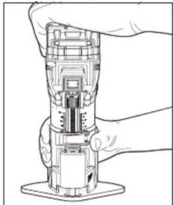
natural_image
Line drawing of a robotic arm gripping a mechanical component (no text or symbols)Accessoire de base plongeante
natural_image
Line drawing of a mechanical presser with hands operating it (no text or symbols present)natural_image
Mechanical assembly diagram showing a rotating component with directional arrows indicating motion (no text or symbols)natural_image
Illustration of hands using a mechanical tool to adjust or install a component on a wooden base (no text or symbols present)natural_image
Illustration of hands operating a mechanical clamp or vise with a wooden base, showing no text or symbols.Milwaukee Tool (Canada) Ltd 1.800.268.4015
Monday-Friday, 7:00 AM - 4:30 PM CST
www.milwaukeetool.ca
GARANTIE LIMITÉE - AUX ÉTATS-UNIS ET AU CANADA
natural_image
Interior view of a kitchen appliance with a magnified inset showing a window and a checkmark (no text or symbols)natural_image
Technical diagram showing a mechanical assembly with an inset close-up of a component (no text or symbols visible)natural_image
Line drawing of a hand operating a mechanical device with a handle (no text or symbols)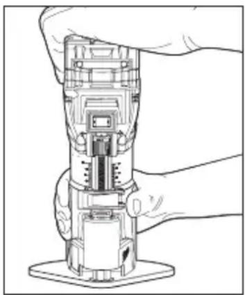
natural_image
Line drawing of a robotic device with a hand holding it, showing internal components and no text or symbols.natural_image
Line drawing of a mechanical presser with hands operating it (no text or symbols present)ADVERTENCIA
natural_image
Mechanical assembly diagram showing a rotating component with directional arrows indicating motion (no text or symbols)natural_image
Line drawing of hands using a mechanical tool to adjust or install a component on a wooden base (no text or symbols)natural_image
Illustration of hands operating a mechanical clamp or vise with a tool, no text or symbols presentLunes a Viernes (9am a 6pm)


- ⚠ WARNING Read all safety warnings, instructions, illustrations and specifica-
- WORK AREA SAFETY
- ELECTRICAL SAFETY
- PERSONAL SAFETY
- POWER TOOL USE AND CARE
- BATTERY TOOL USE AND CARE
- SERVICE
- SPECIFIC SAFETY RULES FOR COMPACT ROUTERS
- WARNING To reduce the risk of injury, when working in dusty situations, wear appropriate respiratory protection or use an OSHA compliant dust extraction solution.
- SPECIFICATIONS
- SYMBOLOGY
- Removing/Inserting the Battery
- Installing Collets
- Installing/Removing Bits
- ⚠ WARNING If the collet nut is not tightened securely, the bit may come out during use, causing serious personal injury.
- Installing/Removing Bases
- ⚠ WARNING To reduce the risk of injury, DO NOT use the router if the quick release lever does not hold the motor securely in the base. If the quick release lever becomes loose, secure the screw with a 3 mm hex wrench to make a snug fit.
- Fixed Base
- Accessory Plunge Base
- Accessory Offset Base
- ⚠ WARNING During use, always keep vacuum hose clear of the path of the bit. Installing a Dust Shroud
- ⚠ WARNING To reduce the risk of injury, do not use the dust shroud when plunge cutting if the bit is larger than the port opening (1-3/8"). If a rotating router bit contacts the dust shroud, the adapter will break and flying debris may cause injury.
- Installing a Straight Edge Guide
- Template Guides
- OPERATION
- AWARNING To reduce the risk of injury, always wear proper eye protection marked to comply with ANSI Z87.1.
- Selecting the Speed
- Feedback Control
- Electronic Overload Protection
- WARNING
- Pressing the macro adjustment button will cause the motor hous-
- Adjusting the Cutting Depth
- Single Pass Cuts
- Multiple Pass Cuts
- Holding the Tool
- Keep hands and body away from the bit and all moving parts.
- Fixed Base and Accessory Offset Base
- ⚠ WARNING To reduce the risk of injury, NEVER use the plunge base in a router
- table.
- WARNING To reduce the risk of injury, always wear eye protection.
- Starting and Stopping the Router Motor
- Making the Cut
- ⚠ WARNING To reduce the risk of injury, avoid "climb cutting." Climb cutting increases the potential for loss of control of the tool and damage to the workpiece. If climb cutting can not be avoided, use extreme caution.
- Fixed Base with a Straight Edge
- AWARNING Always hold the handles firmly with both hands during operation.
- NEVER use the plunge base in a router table.
- MAINTENANCE
- ⚠ WARNING To reduce the risk of injury, always unplug the charger and remove the battery pack from the charger or tool before performing any maintenance. Never disassemble the tool, battery pack or charger. Contact a MILWAUKEE service facility for ALL repairs.
- Maintaining Tool
- WARNING To reduce the risk of personal injury and damage, never immerse your tool, battery pack or charger in liquid allow a liquid to flow inside them.
- Cleaning
- Repairs
- ACCESSORIES
- WARNING Use only recommended accessories. Others may be hazardous.
- SERVICE - UNITED STATES
- 1-800-SAWDUST (1.800.729.3878)
- SERVICE - CANADA
- Milwaukee Tool (Canada) Ltd 1.800.268.4015
- LIMITED WARRANTY USA & CANADA
- LIMITED WARRANTY - MEXICO, CENTRAL AMERICA & CARIBBEÁN
- Procedure to make this warranty valid
- Exceptions
- Accessoire de base plongeante
- GARANTIE LIMITÉE - AUX ÉTATS-UNIS ET AU CANADA
- ADVERTENCIA
Brand : MILWAUKEE
Model : 272320
Category : Electric saw