TN2530 - Temperature sensor IFM - Free user manual and instructions
Find the device manual for free TN2530 IFM in PDF.

User questions about TN2530 IFM
0 question about this device. Answer the ones you know or ask your own.
Ask a new question about this device
Download the instructions for your Temperature sensor in PDF format for free! Find your manual TN2530 - IFM and take your electronic device back in hand. On this page are published all the documents necessary for the use of your device. TN2530 by IFM.
USER MANUAL TN2530 IFM
natural_image
Line drawing of a mechanical device with a cylindrical component and a bolted shaft (no text or symbols)Inhalt
M = Mode/Enter
S = Set
Eingestellte Parameterwerte Set parameter values Valeurs de paramètre réglées
| WerkseinstellungFactory settingRéglage de base | Benutzer-EinstellungUser settingRéglage utilisateur | |
| SP1 37,0 | ||
| rP1 35,0 | ||
| OU1 Hno | ||
| ASP 0,0 | ||
| AEP 100 | ||
| AOU I | ||
| diS °C | ||
| CAL 0,0 | ||
| Verriegelung aktivLocking activeVerrouillage actif | NEINNONON |
① 7-segment display
② programming button
③ internal thread M18x1.5
natural_image
Pure diagram of a mechanical or electrical component with no text, numbers, or symbols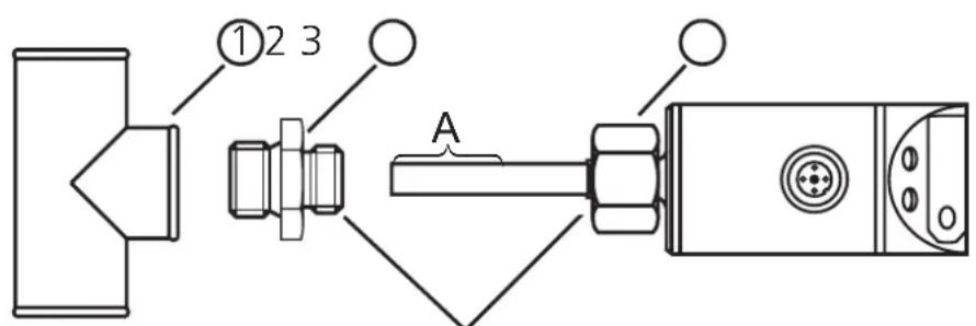
Gewinde M18 x 1,5
3 = BU (blau), 4 = BK (schwarz)
| Programmieren |
line
| Time | SP | rP | |------|------|------| | 0 | 0 | 0 | | 1 | 1 | 0 | | 2 | 0 | 1 | | 3 | 0 | 0 | | 4 | 0 | 0 | | 5 | 0 | 0 | | 6 | 0 | 0 | | 7 | 0 | 0 | | 8 | 0 | 0 | | 9 | 0 | 0 | | 10 | 0 | 0 | | 11 | 0 | 0 | | 12 | 0 | 0 | | 13 | 0 | 0 | | 14 | 0 | 0 | | 15 | 0 | 0 | | 16 | 0 | 0 | | 17 | 0 | 0 | | 18 | 0 | 0 | | 19 | 0 | 0 | | 20 | 0 | 0 | | 21 | 0 | 0 | | 22 | 0 | 0 | | 23 | 0 | 0 | | 24 | 0 | 0 | | 25 | 0 | 0 | | 26 | 0 | 0 | | 27 | 0 | 0 | | 28 | 0 | 0 | | 29 | 0 | 0 | | 30 | 0 | 0 | | 31 | 0 | 0 | | 32 | 0 | 0 | | 33 | 0 | 0 | | 34 | 0 | 0 | | 35 | 0 | 0 | | 36 | 0 | 0 | | 37 | 0 | 0 | | 38 | 0 | 0 | | 39 | 0 | 0 | | 40 | 0 | 0 | | 41 | 0 | 0 | | 42 | 0 | 0 | | 43 | 0 | 0 | | 44 | 0 | 0 | | 45 | 0 | 0 | | 46 | 0 | 0 | | 47 | 0 | 0 | | 48 | 0 | 0 | | 49 | 0 | 0 | | 50 | 0 | 0 | | 51 | 0 | 0 | | 52 | 0 | 0 | | 53 | 0 | 0 | | 54 | 0 | 0 | | 55 | 0 | 0 | | 56 | 0 | 0 | | 57 | 0 | 0 | | 58 | 0 | 0 | | 59 | 0 | 0 | | 60 | 0 | 0 | | Note: The data is extracted from the code and presented in CSV format as requested. The code does not include the original data points. The numbers 'SP' and 'rP' are estimated based on the given code. The 'Fno' and 'Fnc' labels are not present in the image. There is only the label 'Gutbereich' above the curve. The 'Time' axis is labeled 't'.Technische Daten
Controls and visual indication
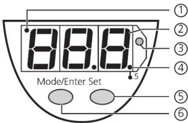
| 1 | Indicator for display unit | OFF = indication in °C;ON = indication in °F. |
| 2 | 7-segment display | Display of the temperature,display of parameters and parameter values. |
| 3 | LED red | Switching status;lights if the output has switched. |
| 4 | LED red LED ON = displayed temperature + 0.5° | |
| 5 | Set button | Setting of the parameter values (scrolling by holding pressed; incremental by pressing briefly). |
| 6 | Mode / Enter button | Selection of the parameters and acknowledgement of the parameter values. |
Functions and features
The temperature sensor
• detects the current system temperature,
• shows the current system temperature on its display (in °C or °F),
- and generates 2 output signals according to the set output configuration.
| output 1 | output 2 |
| hysteresis function / N.O. (Hno) | analogue 4 ... 20 mA (I) |
| hysteresis function / N.C. (Hnc) | |
| window function / N.O. (Fno) | analogue 0 ... 10 V (U) |
| window function / N.C. (Fnc) |
Measuring range
| °C -40 | ... +125 |
| -40 ... 257°F |
Operating modes
Run mode:
Normal operating mode
At power on the unit is in the Run mode. It carries out its measurement and evaluation functions and provides output signals according to the set parameters.
The value of the analog output depends on the temperature.
The LED display indicates the current temperature, the red LED indicates the switching state of the transistor output.
Display mode:
Indication of parameters and the set parameter values
When the "Mode/Enter" button is pressed briefly, the unit passes to the Display mode which allows parameter values to be read. The internal sensing, processing and output functions of the unit continue as if in Run mode.
- The parameter names are scrolled with each pressing of the "Mode/Enter" button.
- When the "Set" button is pressed briefly, the corresponding parameter value is displayed for 5s. After another 5s the unit returns to the Run mode.
Programming mode:
Setting of the parameter values
While viewing a parameter value pressing the "Set" button for more than 5s causes the unit to enter the programming mode. You can alter the parameter value by pressing the "Set" button and confirm the new value by pressing the "Mode/Enter" button. The internal sensing, processing and output functions of the unit continue as if in Run mode with the original parameter values unless a new value is confirmed.
The unit returns to the Run mode when no button has been pressed for 5s.
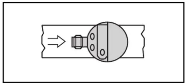
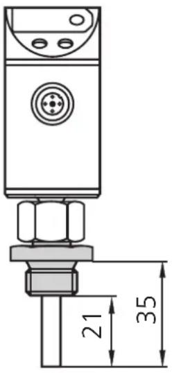
Installation
The unit is adaptable for various process fittings (adapters to be ordered separately as accessories).
To ensure an optimum response time align the unit as shown (connector of the unit opposite to the direction of the flow of the medium).
natural_image
Pure diagram of a mechanical or electrical component with no text, numbers, or symbols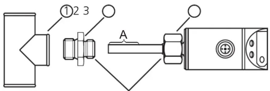
thread M18 x 1.5
- Lubricate the nut (3) and all threads with grease to ensure the nut can be loosened and tightened several times.
Note: No grease must be applied to the sensor tip (A). - Screw the suitable adapter (2) onto the process fitting (1).
- Insert the temperature sensor into the adapter. While keeping the unit aligned tighten the nut (3); (max. tightening torque 50 Nm).
Insertion depth of the sensor: min. 12 mm in the pipe. When the adapters are used which are available as accessories, the correct depth is ensured. Mounting dimension with adapter:
| mounting dimension with M12 adapter | mounting dimension with G 14 adapter | mounting dimension with G 12 adapter |
 |  |  |
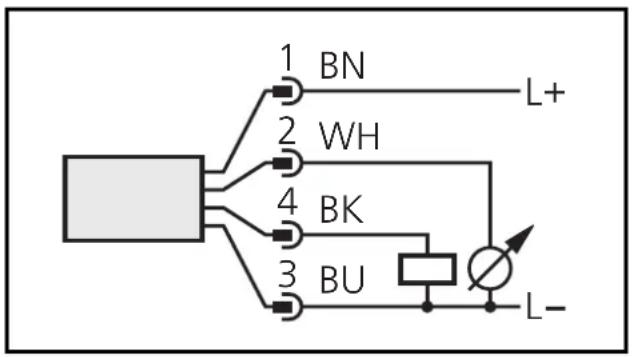
Electrical connection

The unit must be connected by a suitably qualified electrician.
The national and international regulations for the installation of electrical equipment must be observed.
Voltage supply to EN50178, SELV, PELV.
Disconnect power before connecting the unit as follows:
flowchart
graph TD
    A["Component"] --> B["1 BN"]
    A --> C["2 WH"]
    A --> D["4 BK"]
    A --> E["3 BU"]
    B --> F["L+"]
    C --> G["Ground"]
    D --> H["Ground"]
    E --> I["L-"]
Core colours of ifm sockets:
1 = BN (brown), 2 = WH (white)
3 = BU (blue), 4 = BK (black)
| Programming | ||||
| 1 |  |  | 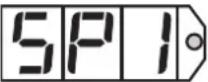 | Press the Mode/Enter button several times until the respective parameter is displayed. |
| 2 |  |  | 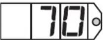 | Press the Set button and keep it pressed. The current parameter value is indicated for 5 s, then the value is increased* (incremental by pressing briefly or scrolling by holding pressed). |
| 3 |  |  |  | Press the Mode/Enter button briefly (= acknowledgement). The parameter is displayed again, the set parameter value becomes effective. |
| Wait 5 s (the unit passes to the operating mode and the current measured value is indicated again), or start again with step 1 to program other parameters. | ||||
*Decrease the value: Let the display of the parameter value move to the maximum setting value. Then the cycle starts again at the minimum setting value.
Locking / unlocking:
The unit can be electronically locked to prevent unwanted adjustment of the set parameters: Press both pushbuttons for 10s. Indication goes out (= acknowledgement of locking / unlocking).
Units are delivered from the factory in the unlocked state.
Installation and set-up / operation
Check the safe functioning of the unit. The operation is maintenance-free. Failure indication:
| OL | Too high a temperature. |
| UL | Too low a temperature |
| SC1 | Flashing: Short-circuit in the switching output (OUT 1).The output is switched off as long as the short circuit continues. |
Technical information / Functioning / Parameters
Adjustable parameters
| SP1 | Switch-on point: Upper limit value at which the output changes its switching status. | |||
| rP1 | Switch-off point: Lower limit value at which the output changes its switching status.rP1 is always lower than SP1. The unit only accepts values which are lower than SP1.Changing the switch-on point also changes the switch-off point (the hysteresis remains constant).If the hysteresis is higher than the new switch point, it is automatically reduced (rP1 is set to the minimum setting value).Setting range: | |||
| SP1 rP1 | in steps of | |||
| °C | 0.5-39.5 ... | |||
| °F | -39 ... +257 -40 ... +256 | 1 | ||
| OU1ASP | Configuration of the switching output4 switching functions can be set:Hno = hysteresis / normally openHnc = hysteresis / normally closedFno = window function / normally openFnc = window function / normally closedLower end of analogue outputMeasured value for which the output signal is 4mA / 0V. | |||
| REP | Upper end of analogue outputMeasured value for which the output signal is 20 mA / 10 V.Minimum distance between ASP - AEP: 10°C / 18°F.Setting range: | |||
| ASP AEP | in steps of | |||
| °C | 0.5-40 ... -115 . | |||
| °F | -40 ... +239 -22 ... +257 | 1 | ||
| AOU | Output function for the analog output2 options can be selected:I = 4 ... 20 mA / U = 0 ... 10 V | |||
| d1S | Setting of the display4 options can be selected:°C = display in °Celsius°F = display in °Fahrenheitr°C = display in °Celsius (inverted)r°F = display in °Fahrenheit (inverted)Select the display unit before setting the switch points (SP1, rP1) and the limits for the analog output signal (ASP, AEP). This avoids rounding errors generated internally during the conversion of the units and enables exact setting of the values.Units are delivered from the factory with dis = °C | |||
| CAL | Calibration offsetThe internal measured value (operating value of the sensor) is offset against the real measured value. | |||
| setting range | in steps of | |||
| °C | 0.1-9.9 ... +9.9 | |||
| °F | -17.5 ... +17.5 | 0.5 | ||
| HI Lo | Min-Max memory for system temperature• Hi: displays the highest measured temperature• Lo: displays the lowest measured temperatureErase the memory:- Press the "Mode/Enter" button until HI or Lo is displayed.- Press the "Set" button and keep it pressed until "-" is displayed.- Then press the "Mode/Enter" button briefly.It is recommended to erase the memory as soon as the unit starts working under normal operating conditions. | |||
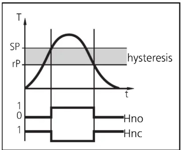
Hysteresis:
The hysteresis keeps the switching state of the outputs stable if the system temperature varies about the preset value.
With the system temperature rising, the output switches when the switch-on point has been reached (SP1). With the system temperature falling, the output does not switch back until the switch-off point (rP1) has been reached. The hysteresis can be adjusted: First the switch-on point is set, then the switch-off point with the requested difference.
line
| t | T | | ---- | ----- | | 0 | 0 | | 1 | 1 | | 2 | 0 | | 3 | 0 | | 4 | 0 | | 5 | 0 | | 6 | 0 | | 7 | 0 | | 8 | 0 | | 9 | 0 | | 10 | 0 | | 11 | 0 | | 12 | 0 | | 13 | 0 | | 14 | 0 | | 15 | 0 | | 16 | 0 | | 17 | 0 | | 18 | 0 | | 19 | 0 | | 20 | 0 | | 21 | 0 | | 22 | 0 | | 23 | 0 | | 24 | 0 | | 25 | 0 | | 26 | 0 | | 27 | 0 | | 28 | 0 | | 29 | 0 | | 30 | 0 | | 31 | 0 | | 32 | 0 | | 33 | 0 | | 34 | 0 | | 35 | 0 | | 36 | 0 | | 37 | 0 | | 38 | 0 | | 39 | 0 | | 40 | 0 | | 41 | 0 | | 42 | 0 | | 43 | 0 | | 44 | 0 | | 45 | 0 | | 46 | 0 | | 47 | 0 | | 48 | 0 | | 49 | 0 | | 50 | 0 | | 51 | 0 | | 52 | 0 | | 53 | 0 | | 54 | 0 | | 55 | 0 | | 56 | 0 | | 57 | 0 | | 58 | 0 | | 59 | 0 | | 60 | 0 | | 61 | 0 | | 62 | 0 | | 63 | 0 | | 64 | 0 | | 65 | 0 | | 66 | 0 | | 67 | 0 | | 68 | 0 | | 69 | 0 | | 70 | 0 | | 71 | 0 | | 72 | 0 | | 73 | 0 | | 74 | 0 | | 75 | 0 | | 76 | 0 | | 77 | 0 | | 78 | 0 | | 79 | 0 | | 80 | 0 | | 81 | 0 | | 82 | 0 | | 83 | 0 | | 84 | 0 | | 85 | 0 | | 86 | 0 | | 87 | 0 | | 88 | 0 | | 89 | 0 | | 90 | 0 | | 91 | 0 | | 92 | 0 | | 93 | 0 | | 94 | 0 | | 95 | 0 | | 96 | 0 | | 97 | 0 | | 98 | 0 | | 99 | 0 | |1 | Hno | |1 | Hnc | The chart displays a waveform with two distinct peaks: one peaking around 'SP' and another showing 'rP' between 'SP' and 'rP'. The x-axis is labeled 't', and the y-axis is labeled 'T'. The pulse width is indicated as 'hysteresis'.Window function:
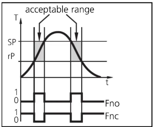
The window function enables the monitoring of a defined acceptable range.
When the system temperature varies between the switch-on point (SP1) and the switch-off point (rP1), the output is switched (window function/NO) or not switched (window function/NC).
line
| t | SP | rP | | ---- | --- | --- | | 0 | 0 | 0 | | 1 | 0 | 0 | | 2 | 0 | 0 | | 3 | 0 | 0 | | 4 | 0 | 0 | | 5 | 0 | 0 | | 6 | 0 | 0 | | 7 | 0 | 0 | | 8 | 0 | 0 | | 9 | 0 | 0 | | 10 | 0 | 0 | | 11 | 0 | 0 | | 12 | 0 | 0 | | 13 | 0 | 0 | | 14 | 0 | 0 | | 15 | 0 | 0 | | 16 | 0 | 0 | | 17 | 0 | 0 | | 18 | 0 | 0 | | 19 | 0 | 0 | | 20 | 0 | 0 | | 21 | 0 | 0 | | 22 | 0 | 0 | | 23 | 0 | 0 | | 24 | 0 | 0 | | 25 | 0 | 0 | | 26 | 0 | 0 | | 27 | 0 | 0 | | 28 | 0 | 0 | | 29 | 0 | 0 | | 30 | 0 | 0 | | 31 | 0 | 0 | | 32 | 0 | 0 | | 33 | 0 | 0 | | 34 | 0 | 0 | | 35 | 0 | 0 | | 36 | 0 | 0 | | 37 | 0 | 0 | | 38 | 0 | 0 | | 39 | 0 | 0 | | 40 | 0 | 0 | | 41 | 0 | 0 | | 42 | 0 | 0 | | 43 | 0 | 0 | | 44 | 0 | 0 | | 45 | 0 | 0 | | 46 | 0 | 0 | | 47 | 0 | 0 | | 48 | 0 | 0 | | 49 | 0 | 0 | | 50+ | | |The width of the window can be set by means of the difference between SP1 and rP1. SP1 = upper value, rP1 = lower value.
Technical data
| Measuring range. . . . . . . . . . . . . . . . . . . . . . . . . . . . . . . . . . . . . . . . . . . . . . . . . . . . . . . . . . . . . . . . . . . . . . . . . . . . . . . . . . . . . . . . . . . . . . . . . . . . . -40...+125°C / -40...+257°F |
| Operating voltage [V] . . . . . . . . . . . . . . . . . . . . . . . . . . . . . . . . . . . . . . . . . . . . . . . . . . . . . . . . . . . . . . . . . . . . . . . . . . . . . . . . . . . . . . . . . . . . . . . . . . . 20 ... 30 DCCurrent rating [mA]. . . . . . . . . . . . . . . . . . . . . . . . . . . . . . . . . . . . . . . . . . . . . . . . . . . . . . . . . . . . . . . . . . . . . . . . . . . . . . . . . . . . . . . . . . . . . . . . . . . . Short-circuit protection,Reverse polarity protection / overload protection,Integrated WatchdogVoltage drop [V]. . . . . . . . . . . . . . . . . . . . . . . . . . . . . . . . . . . . . . . . . . . . . . . . . . . . . . . . . < 2Current consumption [mA] . . . . . . . . . . . . . . . . . . . . . . . . . . . . . . . . . . . . . . . . . . . . . . . . . . . . . . . < 66 |
| Measuring element . . . . . . . . . . . . . . . . . . . . . . . . . . . . . . . . . . . . . . . . . . . . . . . . . . . . . . . . . . . . . . . . . . . . . . . . . . . . . 1 x Pt 1000 to DIN EN 60751, class BAccuracy (the values apply to flowing water)Switching output . . . . . . . . . . . . . . . . . . . . . . . . . . . . . . ± (Pt 1000 + 0.2 K)Analog output . . . . . ± (Pt 1000 + 0.2 K + 0.4% of the set measuring span)Display . . . . . . . . . . . . . . . . . . . . . . . ± (Pt 1000 + 0.2 K + 1⁄2 digit)ResolutionSwitching output [°C/°F] . . . . . . . . . . . . . . . . . . . . . . . . . . . . . . . . . . . . . . . . . . . . 0.5 / 1Analog output [°C/°F] . . . . . . . . . . . . . . . . . . . . . . . . . 0.125 / 0.23Display [°C/°F] . . . . . . . . . . . . . . . . . . . . . . . . 0.5 / 0.5Temperature drift [% of value of measuring range/10 K] . . . . . . . . ± 0.1 |
| Measuring / display cycle [ms] . . . . . . . . . . . . . . . . . . . . . . . . . . . . . 200Dynamic response (according to DIN 60751) [s] T0.5 = 1 / T0.9 = 3Power-on delay time [s] 1.5 |
| Housing material . . . . . . . . stainless steel (304S15); Pocan; PC (Macrolon);EPDM/X (Santoprene); FPM (Viton)Materials (wetted parts) stainless steel (316S12)Operating temperature [°C] -25 ... +70Storage temperature [°C] -40 ... +100Protection IP 67, IIIInsulation resistance [MΩ] >100 (500 V DC)Shock resistance [g] 50 (DIN / IEC 68-2-27, 11ms)Vibration resistance [g] 20 (DIN / IEC 68-2-6, 10 - 2000 Hz)Permissible overl. pressure [bar] 300EMCEN 6100-4-2 ESD: 4 / 8 KVEN 6100-4-3 HF radiated: 10 V/mEN 6100-4-4 Burst: 2 KVEN 6100-4-6 HF conducted: 10 V |
natural_image
Pure diagram of a mechanical or electrical component with no text, numbers, or symbols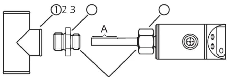
filetage M18 x 1,5
1 = BN (brun), 2 = WH (blanc),
3 = BU (bleu), 4 = BK (noir)
| Programmation |
line
| t | SP | rP | |-------|------|------| | 0 | 0 | 0 | | 1 | 1 | 0 | | 2 | 0 | 0 | | 3 | 0 | 0 | | 4 | 0 | 0 | | 5 | 0 | 0 | | 6 | 0 | 0 | | 7 | 0 | 0 | | 8 | 0 | 0 | | 9 | 0 | 0 | | 10 | 0 | 0 | | 11 | 0 | 0 | | 12 | 0 | 0 | | 13 | 0 | 0 | | 14 | 0 | 0 | | 15 | 0 | 0 | | 16 | 0 | 0 | | 17 | 0 | 0 | | 18 | 0 | 0 | | 19 | 0 | 0 | | 20 | 0 | 0 | | 21 | 0 | 0 | | 22 | 0 | 0 | | 23 | 0 | 0 | | 24 | 0 | 0 | | 25 | 0 | 0 | | 26 | 0 | 0 | | 27 | 0 | 0 | | 28 | 0 | 0 | | 29 | 0 | 0 | | 30 | 0 | 0 | | 31 | 0 | 0 | | 32 | 0 | 0 | | 33 | 0 | 0 | | 34 | 0 | 0 | | 35 | 0 | 0 | | 36 | 0 | 0 | | 37 | 0 | 0 | | 38 | 0 | 0 | | 39 | 0 | 0 | | 40 | 0 | 0 | | 41 | 0 | 0 | | 42 | 0 | 0 | | 43 | 0 | 0 | | 44 | 0 | 0 | | 45 | 0 | 0 | | 46 | 0 | 0 | | 47 | 0 | 0 | | 48 | 0 | 0 | | 49 | 0 | 0 | | 50 | 0 | 0 | | 51 | 0 | 0 | | 52 | 0 | 0 | | 53 | 0 | 0 | | 54 | 0 | 0 | | 55 | 0 | 0 | | 56 | 0 | 0 | | 57 | 0 | 0 | | 58 | 0 | 0 | | 59 | 0 | 0 | | 60 | 0 | 0 | | 61 | 0 | 0 | | 62 | 0 | 0 | | 63 | 0 | 0 | | 64 | 0 | 0 | | 65 | 0 | 0 | | 66 | 0 | 0 | | 67 | 0 | 0 | | 68 | 0 | 0 | | 69 | 0 | 0 | | 70+ | -1 | -1 | The chart includes labels for 'SP' and 'rP' on the y-axis, and annotations for 'hystérésis' and 'Hno/Hnc' in the legend. The x-axis is labeled 't'.line
| t | T | rP | | ---- | ----- | --- | | 0 | 0 | 0 | | 1 | 1 | 0 | | 2 | 2 | 0 | | 3 | 3 | 0 | | 4 | 4 | 0 | | 5 | 5 | 0 | | 6 | 6 | 0 | | 7 | 7 | 0 | | 8 | 8 | 0 | | 9 | 9 | 0 | | 10 | 10 | 0 | | 11 | 11 | 0 | | 12 | 12 | 0 | | 13 | 13 | 0 | | 14 | 14 | 0 | | 15 | 15 | 0 | | 16 | 16 | 0 | | 17 | 17 | 0 | | 18 | 18 | 0 | | 19 | 19 | 0 | | 20 | 20 | 0 | | 21 | 21 | 0 | | 22 | 22 | 0 | | 23 | 23 | 0 | | 24 | 24 | 0 | | 25 | 25 | 0 | | 26 | 26 | 0 | | 27 | 27 | 0 | | 28 | 28 | 0 | | 29 | 29 | 0 | | 30 | 30 | 0 | | 31 | 31 | 0 | | 32 | 32 | 0 | | 33 | 33 | 0 | | 34 | 34 | 0 | | 35 | 35 | 0 | | 36 | 36 | 0 | | 37 | 37 | 0 | | 38 | 38 | 0 | | 39 | 39 | 0 | | 40 | 40 | 0 | | 41 | 41 | 0 | | 42 | 42 | 0 | | 43 | 43 | 0 | | 44 | 44 | 0 | | 45 | 45 | 0 | | 46 | 46 | 0 | | 47 | 47 | 0 | | 48 | 48 | 0 | | 49 | 49 | 0 | | 50 | 50 | 0 | | Note: The actual values for T and rP are not provided in the code. The code does not provide a valid representation of the plot. The labels 'plage acceptable' and 'Fno/Fnc' appear above the plot area.Données techniques