
TN7530 - Temperature sensor IFM - Free user manual and instructions
Find the device manual for free TN7530 IFM in PDF.

| Product type | Electronic temperature sensor |
| Brand | IFM |
| Model | TN7530 |
| Measuring range | -40 to +125°C / -40 to +257°F |
| Supply voltage | 18 to 30 V DC |
| Output current | 250 mA |
| Power consumption | < 50 mA |
| Measuring element | Pt 1000 class B |
| Accuracy | ± (Pt1000 + 0.2 K) |
| Output resolution | 0.5°C / 1°F |
| Display | Digital, resolution 0.5°C / 0.5°F |
| Response time | T0.5 = 1 s, T0.9 = 3 s |
| Protection rating | IP67, class III |
| Housing material | Stainless steel 304, PBTP, PC, EPDM/X, FPM |
| Fluid contact material | Stainless steel 316L |
| Ambient temperature | -25 to +70°C |
| Storage temperature | -40 to +100°C |
| Permissible overpressure | 300 bar |
| Output functions | Hysteresis (NO/NC), Window (NO/NC) |
| Number of outputs | 2 transistor outputs |
| Calibration | Adjustable zero offset |
| Memory | Max/min temperature |
| Locking | Yes (programming) |
| Mounting | Thread M18x1.5, nut 50 Nm max |
| Connection | M12 connector |
Frequently Asked Questions - TN7530 IFM
User questions about TN7530 IFM
0 question about this device. Answer the ones you know or ask your own.
Ask a new question about this device
Download the instructions for your Temperature sensor in PDF format for free! Find your manual TN7530 - IFM and take your electronic device back in hand. On this page are published all the documents necessary for the use of your device. TN7530 by IFM.
USER MANUAL TN7530 IFM
Controls and visual indication . page 16
Function and features page 17
Operating modes. page 17
Installation page 19
Electrical connection page 20
Programming page 21
Installation and set-up / operation 22
Technical information / Functioning / Parameters Adjustable parameters 22
Technical data page 25
Scale drawing . page 5
Contenu
OUT1 = Hno, OUT2 = Hnc,
SP1 = SP2 / rP1 = rP2.
Programmieren
Hnc = Hysteresefunction / normally closed (Öffner)
Fno = Fensterfungtion / normally open (Schlieber)
Fnc = Fensterfunktion / normally closed (Offner)
+12!
Controls and visual indication
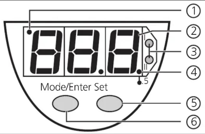
| ① | Indicator for display unit | OFF = indication in °C; ON = indication in °F |
| ② | 7-segment display | display of the system temperature, display of parameters and parameter values |
| ③ | 2 x LED red | switching status; lights if output I / II has switched |
| ④ | LED red LED | ON = displayed temperature + 0.5° |
| ⑤ | Set button | setting of the parameter values (scrolling by holding pressed; incremental by pressing briefly) |
| ⑥ | Mode / Enter button | selection of the parameters and acknowledgement of the parameter values |
Functions and features
- The temperature sensor detects the current system temperature,
- shows the current system temperature on its display (in ^ C or ^ F ),
- and generates 2 output signals according to the set output configuration.
| output 1 output 2 | |
| Switching function (can be selected for each output separately) | hysteresis function / N.O. (Hno) |
| hysteresis function / N.C. (Hnc) | |
| window function / N.O. (Fno) | |
| window function / N.C. (Fnc) |
Measuring range:
| °C -40 | ... +125 |
| -40 ... 257°F |
Operating modes
Run mode:
Normal operating mode
When the supply voltage has been applied, the unit is in the Run mode. It monitors and switches the transistor outputs according to the set parameters..
The LED display indicates the current system temperature, the red LEDs indicate the switching state of the transistor outputs.
Display mode:
Indication of parameters and the set parameter values
When the "Mode/Enter" button is pressed briefly, the unit passes to the Display mode which allows parameter values to be read. The internal sensing, processing and output functions of the unit continue as if in Run mode.
- The parameter names are scrolled with each pressing of the "Mode/Enter" button.
- When the "Set" button is pressed briefly, the corresponding parameter value is displayed for 5 s. After another 5 s the unit returns to the Run mode.
Programming mode:
Setting of the parameter values
The unit passes to the programming mode when after the selection of a parameter value (Display mode) the "Set" button is pressed until the display of the parameter value is changed. Internally the unit remains in the operating mode. It continues its monitoring function with the existing parameters until the change has been terminated.
You can change the parameter value by pressing the "Set" button and confirm it by pressing the "Mode/Enter" button. The unit returns to the Run mode when no button has been pressed for 5 s.
Installation
The unit is adaptable for various process fittings (adapters to be ordered separately as accessories).
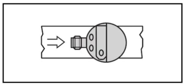
To ensure an optimum response time align the unit as shown (connector of the unit opposite to the direction of the flow of the medium).
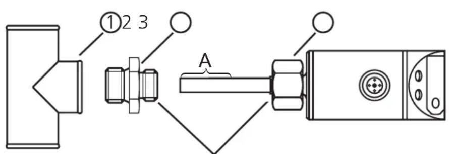
thread M18 x 1.5
- Lubricate the nut (3) and all threads with grease to ensure the nut can be loosened and tightened several times.
Note: No grease must be applied to the sensor tip (A). - Screw the suitable adapter (2) onto the process fitting (1).
- Insert the temperature sensor into the adapter. While keeping the unit aligned tighten the nut (3); (max. tightening torque 50 Nm).
Insertion depth of the sensor: min. 12 mm in the pipe. When the adapters are used which are available as accessories, the correct depth is ensured.
Note: The sensor tip must not touch the pipe wall.
| mounting dimension with M12 adapter | mounting dimension with G¼ adapter | mounting dimension with G½ adapter |
| 135 27 | 135 27 | 21 35 |
Electrical connection
The unit must only be connected by an electrician.
The national and international regulations for the installation of electrical equipment must be observed.
Voltage supply to EN50178, SELV, PELV.
Disconnect power before connecting the unit.
Wiring:
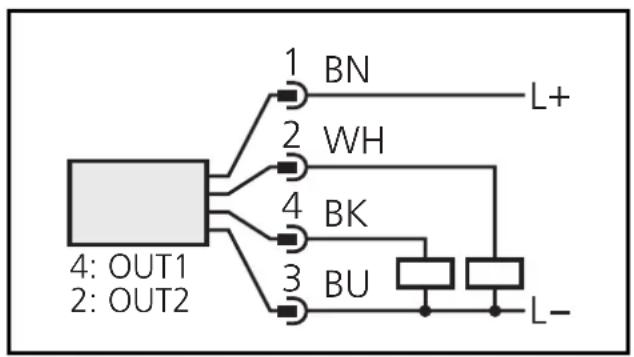
Core colours of ifm sockets:
1 = BN (brown), 2 = WH (white)
3 = BU (blue), 4 = BK (black)
Programming of complementary outputs:
output 1: = Hno, output 2: = Hnc,
SP1 = SP2 / rP1 = rP2.
Programming
| 1 | Mode/Enter Set | →SP1 | Press the Mode/Enter button several times until the respective parameter is displayed. |
| 2 | Mode/Enter Set | →70 | Press the Set button and keep it pressed. The current parameter value is indicated for 5 s, then the value is increased* (incremental by pressing briefly or scrolling by holding pressed). |
| →100 | |||
| 3 | Mode/Enter Set | →SP1 | Press the Mode/Enter button briefly (= acknowledgement). The parameter is displayed again, the set parameter value becomes effective. |
| Wait 5 s (the unit passes to the operating mode and the current measured value is indicated again), or start again with step 1 to program other parameters. | |||
*Decrease the value: Let the display of the parameter value move to the maximum setting value. Then the cycle starts again at the minimum setting value.
Locking / unlocking:
The unit can be electronically locked to prevent unwanted adjustment of the set parameters: Press both pushbuttons for 10s. Indication goes out (= acknowledgement of locking / unlocking).
Units are delivered from the factory in the unlocked state.
Installation and set-up / operation
Check the safe functioning of the unit. The operation is maintenance-free. Failure indication:
| OL | = too high a temperature |
| UL | = too low a temperature |
| SC1 | (FLASHING) = short-circuit in switching output 1/2; the respective output is switched off. |
| SC2 |
Technical information / Functioning / Parameters
Adjustable parameters
| SP1 SP2 | Switch-on point Upper limit value at which the output changes its switching status. | ||
| rP1 rP2 | Switch-off point Lower limit value at which the output changes its switching status. rPx is always lower than SPx. The unit only accepts values which are lower than SPx. Changing the switch-on point also changes the switch-off point (the hysteresis remains constant). If the hysteresis is higher than the new switch point, it is automatically reduced (rPx is set to the minimum setting value). Setting ranges: | ||
| SP1 rP1 | in Schritten von | ||
| °C | 0.5-39.5 ... +129 | ||
| °F | -39 ... +257 -40 ... +256 | 1 | |
| Configuration of the switching outputs 4 switching functions can be set: Hno = hysteresis / normally open Hnc = hysteresis / normally closed Fno = window function / normally open Fnc = window function / normally closed | |||
| d15 | Setting of the display 4 options can be selected: °C = display in °Celsius °F = display in °Fahrenheit r°C = display in °Celsius (inverted) r°F = display in °Fahrenheit (inverted) | ||
| Select the display unit before setting the switch points (SPx, rPx). This avoids rounding errors generated internally during the conversion of the units and enables exact setting of the values. Units are delivered from the factory with dis = °C | |||
| CAL | Calibration offset The internal measured value (operating value of the sensor) is offset against the real measured value. | ||
| setting range | in steps of | ||
| °C | -17.5 ... +17.5 | 0.1-9.9 ... 0.5 | |
| °F | |||
| Hi Lo | Min-Max memory for system temperature • Hi: displays the highest measured temperature • Lo: displays the lowest measured temperature Erase the memory: - Press the "Mode/Enter" button until HI or Lo is displayed. - Press the "Set" button and keep it pressed until "-" is displayed. - Then press the "Mode/Enter" button briefly. It is recommended to erase the memory as soon as the unit starts working under normal operating conditions. | ||
Hysteresis:
The hysteresis keeps the switching state of the outputs stable if the system temperature varies about the preset value.
When the system temperature is rising, the output switches when the switch-on point has been reached (SPx); when the system temperature is falling again, the output switches back when the switch-off point (rPx) has been
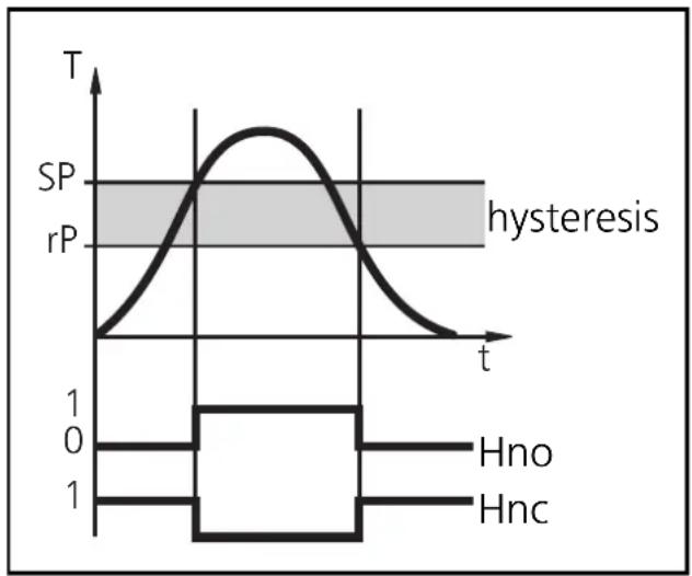
reached. The hysteresis can be adjusted: First the switch-on point is set, then the switch-off point with the requested difference.
Window function:
The window function enables the monitoring of a defined acceptable range.
When the system temperature varies between the switch-on point (SPx) and the switch-off point (rPx), the output is switched (window function/NO) or not switched (window function/NC).
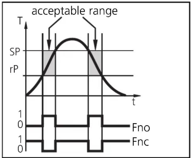
The width of the window can be set by means of the difference between SPx and rPx. SPx = upper value, rPx = lower value.
Technical data
| Measuring range. | -40...+125°C / -40...+257°F |
| Operating voltage [V] | 18 ... 30 DC |
| Current rating [mA]. | 250 Short-circuit protection, Reverse polarity protection / overload protection, Integrated Watchdog |
| Voltage drop [V]. | < 2 |
| Current consumption [mA] | < 50 |
| Measuring element | 1 x Pt 1000 to DIN EN 60751, class B |
| Accuracy (the values apply to flowing water) | |
| Switching output | ± (Pt 1000 + 0.2 K) |
| Display | ± (Pt 1000 + 0.2 K + 1/2 digit) |
| Resolution | |
| Switching output [°C/°F] | 0.5 / 1 |
| Display [°C/°F] | 0.5 / 0.5 |
| Temperature drift [% of value of measuring range/10 K] | ± 0.1 |
| Measuring / display cycle [ms] | 200 |
| Dynamic response (according to DIN EN 60751) [s] | T0.5 = 1 / T0.9 = 3 |
| Power-on delay time [s] | 1.5 |
| Housing material | stainless steel (304S15); Pocan; PC (Macrolon); EPDM/X (Santoprene); FPM (Viton) |
| Materials (wetted parts) | stainless steel (316S12) |
| Operating temperature [°C] | -25 ... +70 |
| Storage temperature [°C] | -40 ... +100 |
| Protection | IP 67, III |
| Insulation resistance [MΩ] | > 100 (500 V DC) |
| Shock resistance [g] | 50 (DIN / IEC 68-2-27, 11ms) |
| Vibration resistance [g] | 20 (DIN / IEC 68-2-6, 10 - 2000 Hz) |
| Permissible overl. pressure [bar] | 300 |
| EMC | |
| EN 61000-4-2 ESD: | 4kV CD / 8kV AD |
| EN 61000-4-3 HF radiated: | 10 V/m |
| EN 61000-4-4 Burst: | 2 KV |
| EN 61000-4-6 HF conducted: | 10 V |

