OL5022 - Photoelectric sensor IFM - Free user manual and instructions
Find the device manual for free OL5022 IFM in PDF.

| Product type | Photoelectric sensor |
| Brand | IFM |
| Model | OL5022 |
| Category | Reflex photoelectric sensor |
| Detection technology | Reflex with honeycomb reflector or reflective adhesive tape |
| Typical range | Up to 80 mm with honeycomb reflector ∅80 mm (exact value on label) |
| Light source | Red laser, class 2 |
| Supply voltage | 10-30 V DC |
| Visual indicators | Red, yellow, green LED |
| Output function | Switching (light/dark), diagnostic output |
| Programming | Adjustment button for sensitivity and output function |
| Connection | 4-pin connector (pin 2 = diagnostic output) |
| Mounting | Bracket mounting, precise alignment required |
| Maintenance | Clean lenses with a soft cloth, no solvents |
| Safety | Class 2 laser radiation, do not stare into beam |
| Warning | Laser warning labels to be affixed near the sensor |
Frequently Asked Questions - OL5022 IFM
User questions about OL5022 IFM
0 question about this device. Answer the ones you know or ask your own.
Ask a new question about this device
Download the instructions for your Photoelectric sensor in PDF format for free! Find your manual OL5022 - IFM and take your electronic device back in hand. On this page are published all the documents necessary for the use of your device. OL5022 by IFM.
USER MANUAL OL5022 IFM
natural_image
Technical line drawing of a mechanical sensor or probe component with no visible text or symbolsnatural_image
Warning symbol with sunburst inside triangle (no text or numbers)Function and features
In conjunction with a prismatic reflector or reflective tape the retro-reflective sensor detects objects and materials without contact and indicates their presence by a switched signal.
Range (r): see type label (value referred to prismatic reflector with ∅ 80mm).
The highly focussed units detect very small objects. Therefore you must use a suitable prismatic reflector (e.g. E20722).
Laser radiation; laser protection class 2.
Do not look directly into the beam!
The enclosed labels (warning laser) must be applied in close proximity to the unit.
Electrical connection
Isolate power, then connect the unit (see page 17 or type label).
Programming of the output function (see page 11).
Load of the function check output (fc output): max. 10mA.
Installation and alignment
LEDs red, yellow, green setting button
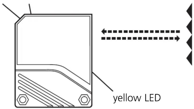
Fix prismatic reflector / reflective tape in desired position. Align the photocell towards the reflector; the light spot must hit the prismatic reflector.
Maximum range is only possible with precise alignment.
Attention: Do not align the beam towards the fixing screw of the prismatic reflector.

Mount the unit so that the mounting position cannot change (in particular avoid high vibrations!). Laser units with a very small light spot diameter are highly focussed; the slightest change in the mounting position will result in misalignment.
Adjustment aid
To make alignment easier the intensity of the light spot is increased during the setting until it becomes clearly visible. In the operating mode (after step 3 of the setting) the transmitted light is set to normal intensity.
NB: Commissioning
The retro-reflective sensor is supplied ready to operate (plug and play) set at the max. sensing range. This is sufficient if the retro-reflective sensor can operate with maximum excess gain (highest contrast). The following setting procedures should only be necessary in less straightforward applications, for example if partly transparent objects must be detected.
Setting of the sensitivity with stationary objects
| 1 | Activate the programming mode of the unit.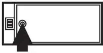 ←→ ←→  Press for about 2s until the red LED flashes. Press for about 2s until the red LED flashes. |
| The red LED goes out; the yellow and green LEDs flash alternately.The unit is in the programming mode. | |
| 2 | Set the sensitivitywithobiect.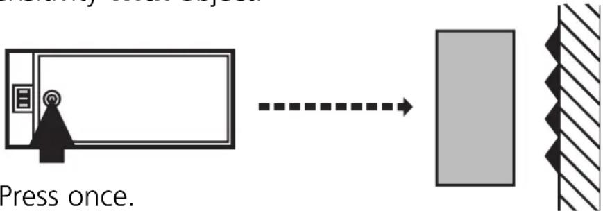 |
| The yellow and green LEDs go out for approx. 1s,then flash again alternately. |
| 3 | Set the sensitivitywithoutobject.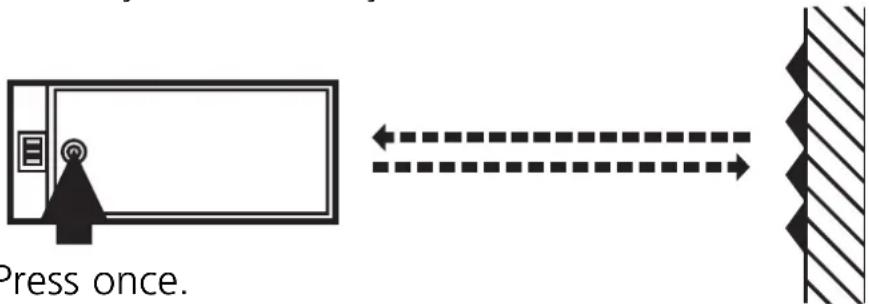 |
| The yellow and green LEDs go out for approx. 1s,then the green LED is on.The unit is in the operating mode. |
You can also proceed in reverse order: first setting without the object, then with the object.

If the setting of the sensitivity is not possible (e.g. object signal and background signal are about the same), the red LED flashes after step 3 for approx. 2s. The unit then passes into the operating mode with the sensitivity being unchanged.
Setting of the sensitivity with moving objects
| 1 | Activate the programming mode of the unit.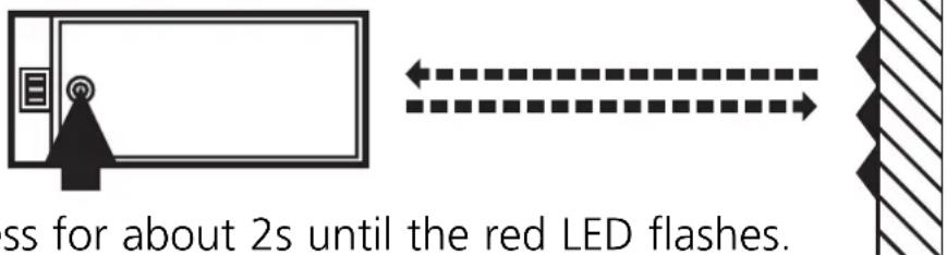 Pre Pre |
| The red LED goes out; the yellow and green LEDs flash alternately. The unit is in the programming mode. |
| 2 | During the measurement (approx. 1s) allow at least two objects to move through the sensing area of the lens.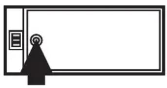 Press once. Press once. |   ↓ ↓ |
| The yellow and green LEDs go out for approx. 1s, then flash again alternately. | ||
| 3 | During the measurement (approx. 1s) allow at least two objects to move through the sensing area of the lens.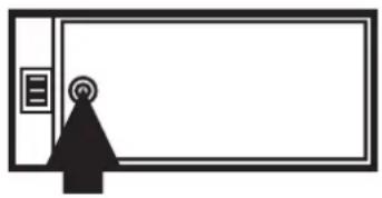 Press once. Press once. |   ↓ ↓ |
| The yellow and green LEDs go out for approx. 1s, then the green LED is on.The unit is in the operating mode. | ||

If the setting of the sensitivity is not possible (e.g. object signal and background signal are about the same), the red LED flashes after step 3 for approx. 2s. The unit then passes into the operating mode with the sensitivity being unchanged.
Setting of the maximum sensitivity
- Go into the programming mode (step 1).
- Align the unit so that no light is reflected.
- Press the setting button twice (see steps 2 and 3).
Programming the output function
 Press for 10s. Press for 10s. |  | The red LED starts to flash fast after 2 s. Then the yellow and green LED's flash alternately. After 8 s all LED's go off, the output function has changed from light-on mode to dark-on mode (or vice versa). |
Operation
Check the safe functioning of the diffuse reflection sensor. Display by LEDs and by the function check output.
| LED green is lit Unit is ready for operation. | |
| LED yellow is lit Output is switched. | |
| LED red is lit | Error in object detection, e.g. maladjustment, soiling of the lenses. |
| LEDs yellow + red | Flash alternately, 2 Hz: output short-circuited. Flash alternately, 1 Hz: internal malfunction (output is not switched). |
Function check output
- Switches in the case of incorrect object detection (error in object detection, maladjustment, soiling of the lenses) after approx. 4 s, it switches back approx. 4 s after the object is again correctly detected.
- Immediately switches in the case of a short circuit of the switching output, it switches back approx. 2 s after the fault has been rectified.
- Immediately switches in the case of an internal fault, it is only switched back by turning off the operating voltage and then on again.
Maintenance
Keep the lens of the sensor free from soiling. For cleaning do not use any solvents or cleaning agents which could damage the plastic lenses.
natural_image
Simple line drawing of a room entrance with a triangular sign and circular icon on the wall (no text or symbols)Appuyer pendant 10s.