OG5067 - Photoelectric sensor IFM - Free user manual and instructions
Find the device manual for free OG5067 IFM in PDF.

| Product type | Laser photoelectric sensor |
| Reference | OG5067 |
| Brand | IFM |
| Detection principle | Photoelectric through-beam (emitter/receiver) |
| Light source | Red laser, class 2 |
| Range | See label (typically up to 20 m) |
| Power supply | 10-30 V DC, galvanic isolation required |
| Switching output | PNP or NPN depending on model (programmable by wiring) |
| Diagnostic output | Yes, 10 mA max |
| LED indicators | Green (power on), Yellow (output active), Red (fault) |
| Connection | 2 m cable (BN, BU, BK) or M12 connector |
| Housing material | Metal (stainless steel) or plastic depending on version |
| Protection rating | IP67 |
| Operating temperature | -25 to +60 °C |
| Dimensions | Approx. 30 x 15 x 15 mm (emitter/receiver) |
| Weight | Approx. 50 g each |
| Mounting | Fixing bracket supplied |
| Sensitivity adjustment | By push button on emitter (3 modes) |
| Operation | Plug and play, maximum range reserve |
| Maintenance | Clean lenses with soft cloth (no solvents) |
| Safety | Do not look into laser beam; affix warning label |
| Special functions | Visible laser adjustment aid, lock/unlock (10 s) |
| Repairability | Spare parts not available; replace the device |
Frequently Asked Questions - OG5067 IFM
User questions about OG5067 IFM
0 question about this device. Answer the ones you know or ask your own.
Ask a new question about this device
Download the instructions for your Photoelectric sensor in PDF format for free! Find your manual OG5067 - IFM and take your electronic device back in hand. On this page are published all the documents necessary for the use of your device. OG5067 by IFM.
USER MANUAL OG5067 IFM
Through-beam sensor OG laser
natural_image
Technical line drawing of a mechanical connector or fitting (no text or symbols)natural_image
Warning symbol with sunburst inside triangle (no text or numbers)Function and features
The through-beam sensor detects objects and materials without contact and indicates their presence by a switched signal.
Range (r): see type label.
Laser radiation; laser protection class 2.
Do not look directly into the beam!
The enclosed labels (warning laser) must be applied in close proximity to the unit.
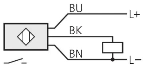
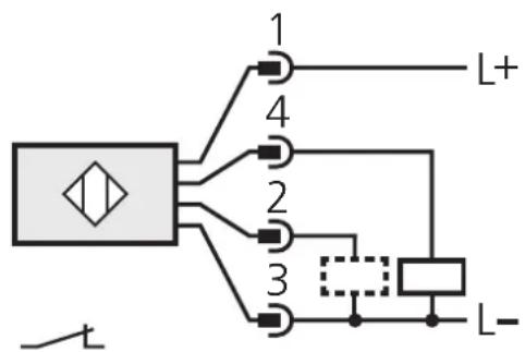
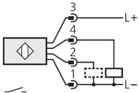
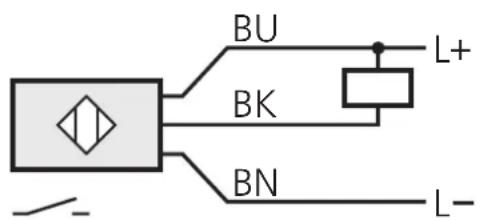
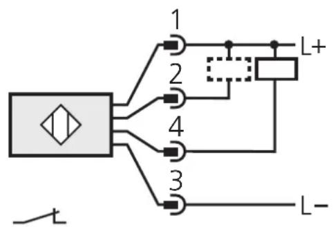
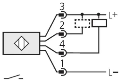
Electrical connection
The device shall be supplied from an isolating source and protected by an overcurrent device such that the limited voltage circuit requirements in accordance with UL 508 are met.
Isolate power, then connect the unit (see page 17 or type label).
Core colours: BN = brown, BU = blue, BK = black.
Programming of the output function by wiring (see page 17 or type label).
Load of the function check output (fc output): max. 10mA.
Installation and alignment
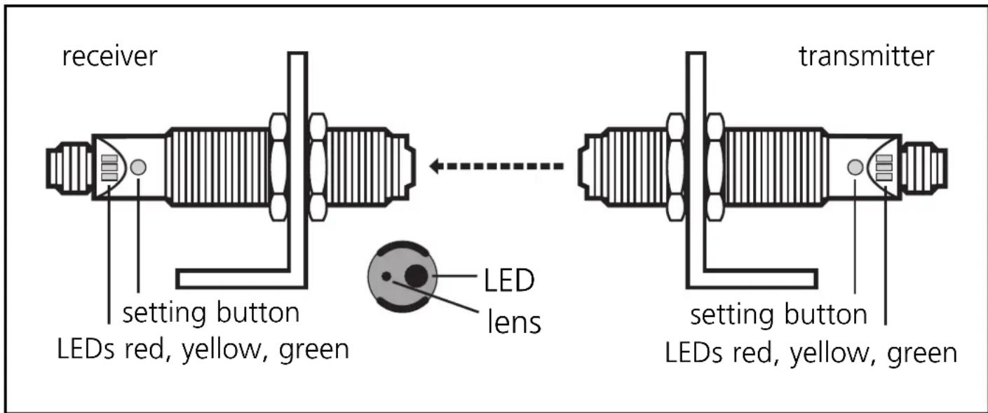
Fix the receiver (type OGEL...) in position.
Align the transmitter (type OGES...) towards the receiver; the light spot must hit the receiver lens (confirmation by LED).

Mount the unit so that the mounting position cannot change (in particular avoid high vibrations!). Laser units with a very small light spot diameter are highly focussed; the slightest change in the mounting position will result in misalignment.
Adjustment aid
For the alignment the transmitter incorporates an adjustment aid.
After pressing the setting button on the transmitter the red LED flashes, then the green LED and the yellow LED flash alternately. The intensity of the transmitted light is increased and the light spot is clearly visible. After pressing the button again the green LED is on again and the transmitted light is set again to normal intensity.
If the button is not pressed again, the transmitted light is set to normal intensity after about 15 min.
NB: Commissioning
The through-beam sensor is supplied ready to operate (plug and play) set at the max. sensing range. This is sufficient if the through-beam sensor can operate with maximum excess gain (highest contrast). The following setting procedures should only be necessary in less straightforward applications, for example if partly transparent objects must be detected.
Setting of the sensitivity with stationary objects
| 1 | Activate the programming mode of the unit.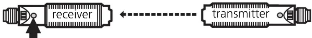 Press for about 2s until the red LED flashes. Press for about 2s until the red LED flashes. |
| The red LED goes out; the yellow and green LEDs flash alternately.The unit is in the programming mode. | |
| 2 | Set the sensitivitywithobject.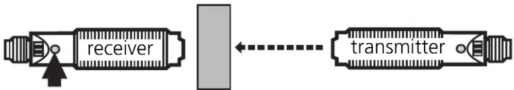 Press once. Press once. |
| The yellow and green LEDs go out for approx. 1s,then flash again alternately. |
| 3 | Set the sensitivitywithoutobject.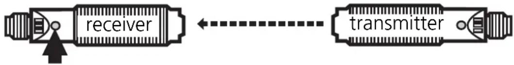 Press once. Press once. |
| The yellow and green LEDs go out for approx. 1s,then the green LED is on.The unit is in the operating mode. |
You can also proceed in reverse order: first setting without the object, then with the object.

If the setting of the sensitivity is not possible (e.g. object signal and background signal are about the same), the red LED flashes after step 3 for approx. 2s. The unit then passes into the operating mode with the sensitivity being unchanged.
Setting of the sensitivity with moving objects
| 1 | Activate the programming mode of the unit.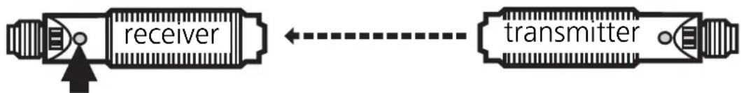 Press for about 2s until the red LED flashes. Press for about 2s until the red LED flashes. |
| The red LED goes out; the yellow and green LEDs flash alternately.The unit is in the programming mode. | |
| 2 | During the measurement (approx. 1s) allow at least two objects to move through the sensing area of the lens.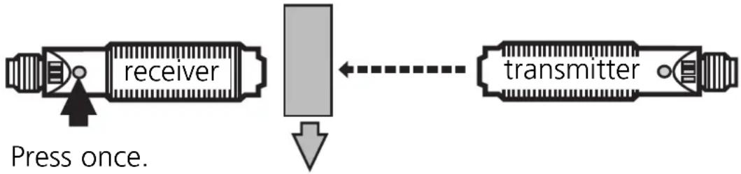 |
| The yellow and green LEDs go out for approx. 1s, then flash again alternately. |
| 3 | During the measurement (approx. 1s) allow at least two objects to move through the sensing area of the lens. |
| The yellow and green LEDs go out for approx. 1s, then the green LED is on.The unit is in the operating mode. |

If the setting of the sensitivity is not possible (e.g. object signal and background signal are about the same), the red LED flashes after step 3 for approx. 2s. The unit then passes into the operating mode with the sensitivity being unchanged.
Setting of the maximum sensitivity
- Go into the programming mode (step 1).
- Interrupt the light beam.
- Press the setting button twice (see steps 2 and 3).
Locking
 Press for 10s. Press for 10s. |  | The red LED flashes for a short time,then the yellow and green LEDsflash alternately;after 10s the LEDs go out, the unitis locked. |
Unlocking
 Press for 10s. Press for 10s. |  | After 10s the LEDs go out, locking is cancelled. |
Operation
Check the safe functioning of the diffuse reflection sensor. Display by LEDs and by the function check output.
| LED green is lit Unit is ready for operation. | |
| LED yellow is lit Output is switched. | |
| LED red is lit | Error in object detection, e.g. maladjustment, soiling of the lenses. |
| LEDs yellow + red | Flash alternately, 2 Hz: output short-circuited. Flash alternately, 1 Hz: internal malfunction (output is not switched). |
Function check output
(not for sensors with cable connection)
- Switches in the case of incorrect object detection (error in object detection, maladjustment, soiling of the lenses) after approx. 4 s, it switches back approx. 4 s after the object is again correctly detected.
- Immediately switches in the case of a short circuit of the switching output, it switches back approx. 2 s after the fault has been rectified.
- Immediately switches in the case of an internal fault, it is only switched back by turning off the operating voltage and then on again.
Maintenance
Keep the lens of the sensor free from soiling. For cleaning do not use any solvents or cleaning agents which could damage the plastic lenses.
flowchart
graph TD
    A["Input"] --> B["1"]
    A --> C["2"]
    A --> D["3"]
    B --> E["L+"]
    C --> F["L-"]
    D --> G["L-"]
    H["Switch"] --> A
flowchart
graph TD
    A["Switch"] --> B["Component 1"]
    A --> C["Component 2"]
    A --> D["Component 3"]
    A --> E["Component 4"]
    B --> F["L+"]
    C --> G["L-"]
    D --> H["L+"]
    E --> I["L-"]
    style A fill:#f9f,stroke:#333
    style B fill:#ccf,stroke:#333
    style C fill:#ccf,stroke:#333
    style D fill:#ccf,stroke:#333
    style E fill:#ccf,stroke:#333
    style F fill:#dfd,stroke:#333
    style G fill:#dfd,stroke:#333
    style H fill:#dfd,stroke:#333
    style I fill:#dfd,stroke:#333
flowchart
graph TD
    A["Switch"] --> B["Gate 1"]
    A --> C["Gate 2"]
    A --> D["Gate 3"]
    A --> E["Gate 4"]
    B --> F["L+"]
    C --> G["Ground"]
    D --> H["Ground"]
    E --> I["L-"]
flowchart
graph TD
    A["Component"] --> B["1"]
    A --> C["2"]
    A --> D["3"]
    A --> E["4"]
    B --> F["L+"]
    C --> G["Ground"]
    D --> H["Ground"]
    E --> I["L-"]
PIN 2 = fc-output