
LI5045 - Level sensor IFM - Free user manual and instructions
Find the device manual for free LI5045 IFM in PDF.
| Brand | IFM |
| Model | LI5045 |
| Product type | Capacitive level sensor |
| Dimensions (L) | 273 mm |
| Active zone | 25 mm (radial detection) |
| Weight | Approx. 120 g |
| Supply voltage | 10 ... 36 V DC |
| Max. output current | 250 mA |
| Main functions | Level detection of aqueous liquids, N.O./N.C. output (selectable by wiring), LED indicators (green, yellow, red) |
| Maintenance and cleaning | Clean the probe if deposits affect switching; check installation height |
| Safety | IP67 protection, Class II, protection against short circuits, reverse polarity, and overload |
| Spare parts and repairability | Repair by manufacturer; mounting accessories available (E43000 - E43007) |
| Ambient temperature | 0 ... +80 °C |
| Fluid temperature | 0 ... +35 °C |
| Max. tank pressure | 0.5 bar (with mounting accessories) |
| Switching frequency | 5 Hz |
Frequently Asked Questions - LI5045 IFM
User questions about LI5045 IFM
0 question about this device. Answer the ones you know or ask your own.
Ask a new question about this device
Download the instructions for your Level sensor in PDF format for free! Find your manual LI5045 - IFM and take your electronic device back in hand. On this page are published all the documents necessary for the use of your device. LI5045 by IFM.
USER MANUAL LI5045 IFM
Operating instructions
Notice utilisateurs

Kapazitiver
Niveauschalter
Capacitive level switch
- Function and features 9
- Installation . page 10
- Electrical connection page 11
- Installation and set-up / operation 12
- Technical data page 13
Contenu
1 = BN(braun), 3 = BU(blau), 4 = BK(schwarz).
1. Function and features
Applications:
The unit was specially designed to meet the requirements of machine tool building. It is specially suitable for monitoring coolant emulsions as well as other hydrous media.
The unit is virtually immune to build-up of almost any kind on the probe (e.g. particles of metal, foam).
The sensor is not suitable for oils, granulates and bulk materials, acids and alkalis. It is not suitable for food and electroplating applications.
In case of doubt ensure the correct function by performing a test in your application.
Description of the function
The sensor detects the level of media in tanks.
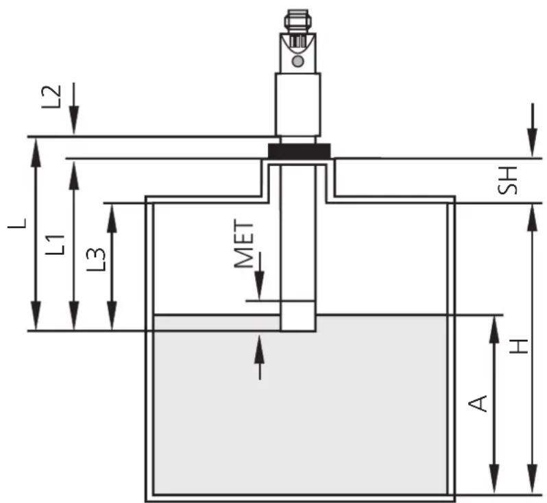
- The unit detects by direct contact with the medium whether the requested level is reached and indicates this by a switched signal (N.O. or N.C., programmable by wiring; page 11).
| level reached level n | pt reached | |
| N.O. | output = ON output | = OFF |
| N.C. | output = OFF output | = ON |
- The level is determined by the installation length ( page 10, Installation).
- The unit is preset at the factory and is immediately ready for operation if used correctly. On delivery the programming button is electronically locked. Programming or adjustment are not necessary!
- Installation: vertical from the top.
The unit operates with radial detection characteristics. Therefore media below the active zone are not detected in the case of vertical installation. Media are only detected when the active zone is covered.
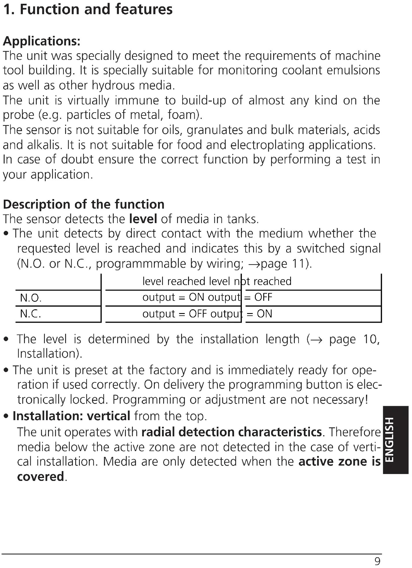
2. Installation
A = response level
H = height of the tank
SH = height of the neck
L = probe length (probe)
L1 = installation length
L2 = outside length
L3 = mounting length
MET = maximum immersion depth (= active zone, 25mm)
Mount the unit vertical from the top.
Mounting length (L3): minimum 60mm.
For safe and easy mounting use the ifm mounting accessories (Order no. E43000 - E43007).

Maximum vessel pressure when mounted with mounting accessories: 0.5bar.
- The units should be used in metal tanks.
Use in plastic tanks is not recommended. When the unit is used in plastic tanks, malfunctions may occur because the electrical contact of the medium to the machine ground may be insufficient.
- The distance between the active zone and the wall/bottom of the metal tank must be min. 20mm .
- When several LI5 units are mounted in one tank minimum distances between them must be maintained: 40mm from the centreline of a probe to the centreline of another probe.
- Distance between sensors type L15xxx and LKxxxx: min. 60mm from the centreline of a probe to the centreline of another probe.
3. Electrical connection

The unit must only be connected by an electrician.
The national and international regulations for the installation of electrical equipment must be observed.
Disconnect power before connecting the unit,
$$ (\text {一} = \quad N. O. 4 \quad / \quad = \quad N. C.) $$
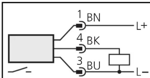
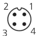
Core colours of ifm sockets:
1 = BN(brown) , 3 = BU(blue) , 4 = BK(black) .
4. Installation and set-up / operation
After mounting and wiring check whether the unit operates correctly. Empty and fill the tank and check whether the unit switches correctly and whether the LED's correctly indicate the operations.
Display by LEDs:
| LED green lights unit is ready for operation | |
| LED yellow lights the output has switched | |
| LED's yellow and red flash quickly (2Hz) | short circuit of the switching output |
| LED red lights function check | |
| LED red flashes quickly (2Hz) in internal fault or unit damaged | |
Function check
The red LED indicates no malfunction of the unit, it indicates that the internal sensor signal is near the switching threshold.
2 cases can be distinguished:
- Normal operation/safe operation
The red LED is lit temporarily when the level of the medium approaches the response level or falls below the response level.
- Warning of possible malfunction
If the red LED is lit continuously, the operating conditions are no longer optimum.
It is for example possible that build-up of dirt on the probe has changed the switching level within the active zone.
You can take preventive measures to avoid a malfunction. Check for example the installation height or clean the unit.
5. Technical data
| Operating voltage [V] | 10 ... 36 DC | ||
| Current rating [mA] | 250;Short-circuit protection;Reverse polarity protection / Overload protectionVoltage drop [V] < 2.5Current consumption [mA] | < 13 (24V DC)Switching frequency [Hz] | 5 |
| Maximum vessel pressure [bar] | 0.5(when mounted with mounting accessories) | ||
| Housing material | PP (polypropylene); TPE/VMaterials (wetted parts) PP (polypropylene) | ||
| Operating temperature [°C] | 0 ... +80Medium temperature [°C] 0 ... +35Protection IP 67, IIEMCIEC 1000-4-2 / EN 61000-4-2: 15kV air discharge / 8kV contact dischargeIEC 1000-4-3 / EN 61000-4-3: 10V/m, 80 ... 1000MHzIEC 1000-4-4 / EN 61000-4-4: 2kV coupling pliersIEC 1000-4-6 / EN 61000-4-6: 10V, 0.15 ... 80MHzIEC 255-5: 1kV |
1 = BN(brun), 3 = BU(bleu), 4 = BK(noir).


Brand : IFM
Model : LI5045
Category : Level sensor