
LI2041 - Level sensor IFM - Free user manual and instructions
Find the device manual for free LI2041 IFM in PDF.
| Product type | Capacitive level sensor |
| Brand | IFM |
| Model | LI2041 |
| Technology | Capacitive |
| Power supply | 10...36 V DC |
| Output current | 250 mA, short-circuit protection |
| Protections | Reverse polarity, overload |
| Protection rating | IP 67, II |
| Ambient temperature | 0...+65 °C (0...+35 °C for aqueous fluids) |
| Fluid temperature | 0...+65 °C (0...+35 °C for aqueous fluids) |
| Max tank pressure | 0.5 bar (with mounting accessories) |
| Housing material | PP (polypropylene) |
| Material in contact with fluid | PP (polypropylene) |
| Probe length | 481 mm |
| Switching frequency | 5 Hz |
| Operation | Level detection of fluids (conductive or non-conductive, εr>1.8) |
| Setting | By push button: empty and full adjustment |
| LED display | Green (power on), yellow (output active), red (fault/control) |
| Mounting | Vertical from top, minimum distance to walls 20 mm, between sensors 200 mm |
| Electrical connection | By electrician, de-energized |
| Safety | Observe national and international standards |
| Maintenance | Clean if deposits; perform a new adjustment if necessary |
Frequently Asked Questions - LI2041 IFM
User questions about LI2041 IFM
0 question about this device. Answer the ones you know or ask your own.
Ask a new question about this device
Download the instructions for your Level sensor in PDF format for free! Find your manual LI2041 - IFM and take your electronic device back in hand. On this page are published all the documents necessary for the use of your device. LI2041 by IFM.
USER MANUAL LI2041 IFM
natural_image
Simple line drawing of a mechanical device with no text or symbolsInhalt
10829 Berlin, 13. November 2006
Kolonnenstraße 30 L
Telefon: 030 78730-370
Telefax: 030 78730-320
GeschZ.: | 53-1.65.13-60/06
Bechlinger Straße 34
88069 Tettnang
A = Ansprechhöhe
H = Behälterhöhe
L = Sondenlänge
L1 = Einbaulänge
L2 = Auszugslänge
M = H öhe Montageadapter
(Aktive Zone) = 25mm
S = Stutzenhöhe
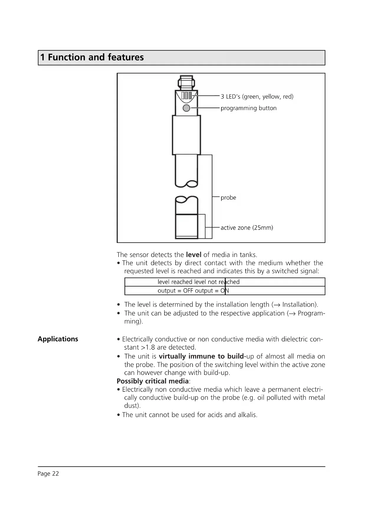
1 Function and features
The sensor detects the level of media in tanks.
- The unit detects by direct contact with the medium whether the requested level is reached and indicates this by a switched signal:
| level reached level not reached |
| output = OFF output = ON |
- The level is determined by the installation length (→ Installation).
- The unit can be adjusted to the respective application ( Programming).
Applications
- Electrically conductive or non conductive media with dielectric constant >1.8 are detected.
- The unit is virtually immune to build-up of almost all media on the probe. The position of the switching level within the active zone can however change with build-up.
Possibly critical media:
- Electrically non conductive media which leave a permanent electrically conductive build-up on the probe (e.g. oil polluted with metal dust).
- The unit cannot be used for acids and alkalis.
2 Installation
A = response level
H = height of the tank
L = probe length
L1 = installation length
L2 = outside length
L3 = mounting length
M = hight of the adapter
S = height of the neck
MET = maximum
immersion depth
(= active zone,
25mm)
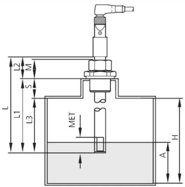
Mount the unit vertical from the top.
Mounting length (L3): minimum 60mm.
For safe and easy mounting use the ifm mounting accessories (Order no. E43000 - E43006).

Maximum vessel pressure when mounted with mounting accessories: 0.5bar.
- If possible, mount the unit in the middle of the tank when it is installed in small plastic tanks:
- When installed in metal tanks the distance between sensor and tank wall / tank bottom must be min. 20mm.
- When several units are installed in a tank, the distance between them should be min. 200mm.
3 Electrical connection

The unit must only be connected by an electrician.
The national and international regulations for the installation of electrical equipment must be observed.
Disconnect power before connecting the unit.
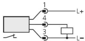
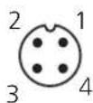
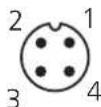
Pin1 = L+
Pin4 = output / normally open
Pin3 = L-
4 Programming
Empty adjustment
After mounting you must adjust the unit to the empty tank.
| 1 | Empty the tankuntil the material is min. 20mm away from the active zone. | |
| 2 | 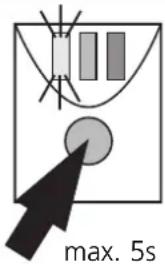 | Press the programming button until the green LED flashes(= the unit is in the adjustment mode).After adjustment the green LED is lit continuously (the unit is in the operating mode). |
- During the empty adjustment the unit determines a measured value for the empty state,
- automatically generates a hypothetical value for the full state (from the measured value for the empty state and a factory predefined signal difference).
- It then sets the optimum switching threshold between the two values.
The unit is then ready for operation.
Full adjustment
For an optimum adjustment of the unit to your application it is recommended to carry out a full adjustment in addition to an empty adjustment as well.
| 1 | Fill the tankuntil the medium covers the active zone. | |
| 2 | 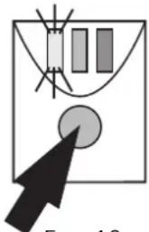 | Press the programming button until the green LED flashes quickly(= the unit is in the adjustment mode).The LED first flashes slowly (about 1Hz), after 5s it flashes double as quickly (about 2Hz).After adjustment the green and yellow LED's are lit continuously (the unit is in the operating mode). |
- During the full adjustment the unit adopts the measured value for the empty state determined during the empty adjustment,
• determines a measured value for the full state and - sets the optimum switching threshold between the two values.
This ensures an optimum adjustment of the unit to your application.
You can repeat the full adjustment as often as you wish. The stored value for the empty state is not overwritten by the full adjustment. When an empty adjustment is made again the previously defined values are overwritten/replaced by the newly determined values. So always carry out the empty adjustment first, then the full adjustment.
4 Programming
Error messages
If the adjustment to the empty or full state is not possible, the red LED flashes quickly after the adjustment attempt (about 2Hz).
To delete this error message press the programming button once or disconnect and then connect power again. The previous adjustment values remain unchanged.
Remove the error cause and then make the adjustment again. Avoid the faults the operator may have made.Possible reasons for an error message:
- The signal difference between the empty and full state is too small (e.g. adjustment to the empty and full state without sufficient change of the level; or too low density of the medium).
- The signal change between the empty and full state is in the wrong order (e.g. adjustment to the empty state when the vessel is full and then adjustment to the full state when the vessel is empty).
- Fault during the empty adjustment (e.g. distance between the medium and active zone is too small or empty adjustment made when there is direct contact with an electrically conductive medium, e.g. water).
Faults of the unit can also disturb the adjustment and result in a fault message:
• Electronic fault or sensing zone of the unit damaged.
- Internal fault (can only be deleted by disconnecting and connecting power again, hardware reset).
Locking / Unlocking
The stored adjustment values can be protected against unauthorised programming: Press the programming button for 10s. The green LED first flashes slowly (about 1Hz), after 5s more quickly. As soon as the indication goes out the unit is locked. Then the green LED is lit, the unit is in the operating mode.
To unlock the unit press the programming button for 10s. After about 10s all LEDs go out briefly, the unit is unlocked.
Units are delivered from the factory in the unlocked state.
5 Installation and set-up / operation
After mounting, wiring and setting check whether the unit operates correctly.
Empty and fill the tank and check whether the unit switches correctly and whether the LED's correctly indicate the operations.
Display by LEDs:
| LED green lights unit is ready for operation | |
| LED yellow lights the output has switched | |
| LED's yellow and red flash quickly (2Hz) | short circuit of the switching output |
| LED red lights function check | |
| LED red flashes quickly (2Hz) in | internal fault or unit damaged |
Function check
The red LED indicates no malfunction of the unit, it indicates that the internal sensor signal is near the switching threshold.
2 cases can be distinguished:
- Normal operation/safe operation
The red LED is lit temporarily when the level of the medium approaches the response level or falls below the response level.
- Warning of possible malfunction
If the red LED is lit continuously, the operating conditions are no longer optimum.
It is for example possible that build-up of dirt on the probe has changed the switching level within the active zone.
You can take preventive measures to avoid a malfunction. For example readjust or clean the unit.
6 Technical data
| Operating voltage [V] . . . . . . . . . . . . . . . . . . . . . . . . . . . . . . . . . . . . . . . . . . . . . . . . . . . . . . . . . . . . . . . . . . . . . . . . . . . . . . . . . . . . . . . . . . . . . . . . . . . . 10 ... 36 DCCurrent rating [mA] . . . . . . . . . . . . . . . . . . . . . . . . . . . . . . . . . . . . . . . . . . . . . . . . . . . . . . . . . . . . . . . . . . . . . . . . . . . . . . . . . . . . . . . . . . . . . . . . . . 250;Short-circuit protection;Reverse polarity protection / Overload protectionVoltage drop [V] < 2.5Current consumption [mA] . . . . . . . . . . . . . . . . . . . . . . . . . . . . . . . . . . . . . . . . . . . . . . . . . . . . . . . . . . . . . . . . . . . . . . . . . . . . . . . . . . . . . . . . . . . . . . . . 5Switching frequency [Hz] . . . . . . . . . . . . . . . . . . . . . . . . . . . . . . . . . . . . . . . . . . . . . . . . . . . . . . . . . . . . . . . . . . . . . . . . . . . . . . . . . . . . . . . . . . . . . . . . . . |
| Maximum vessel pressure [bar] . . . . . . . . . . . . . . . . . . . . . . . . . . . . . . . . . . . . . . . . . . . . . . . . . . . . . . . . . . . . . . . . . . . . . . . . . . . . . . . . . . . . . . . . . . . . . . . . . . (when mounted with mounting accessories) |
| Housing material. . . . . . . . . . . . . . . . . . . . . . . . . . PP (polypropylene); TPE/VMaterials (wetted parts) . . . . . . . . . . . . . . . . . . . . PP (polypropylene) |
| Operating temperature [°C] . . . . . . . . . . . . . . . . . . . . . . . . . . . . . . . . . . . . . . . . . . . . . . . . . . . . . . . . . . . . . . . . . . . . . . . . . . . . . . . . . . . . . . . . . . . . . . . . . . Medium temperature [°C] . . . . . . . . . . . . . . . . . . . . . . . . . . . . . . . . . . . . . . . . . . . . . . . . . . . . . . . . . . . . . . . . . . . . . . . . . . . . . . . . Protection. IP 67, IIEMCIEC 1000-4-2 / EN 61000-4-2: .. 15kV air discharge / 8kV contact dischargeIEC 1000-4-3 / EN 61000-4-3: 10V/m, 80 ... 1000MHzIEC 1000-4-4 / EN 61000-4-4: 2kV coupling pliersIEC 1000-4-6 / EN 61000-4-6: 10V, 0.15 ... 80MHzIEC 255-5: 1kV |
*for water and hydrous media
Scale drawing
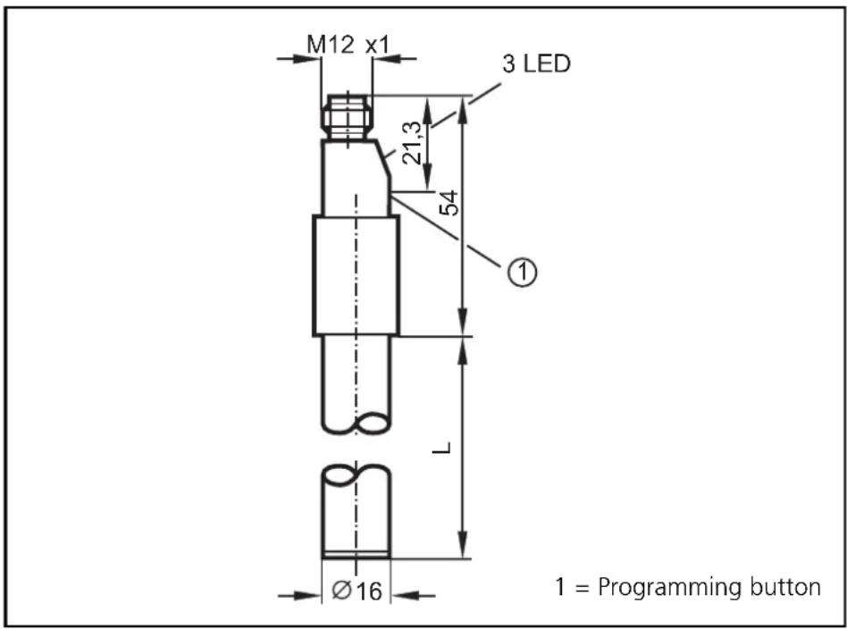
| LI2043LI2042LI20 | |||
| L = probe length [mm] | 481273132 |
Pin1 = L+ Pin4 = sortie / N.F. Pin3 = L-
4 Programmation
Réglage vide


- Inhalt
- Function and features
- Applications
- Possibly critical media:
- Installation
- Mounting length (L3): minimum 60mm.
- Electrical connection
- Programming
- Empty adjustment
- The unit is then ready for operation.
- Full adjustment
- This ensures an optimum adjustment of the unit to your application.
- Error messages
- Locking / Unlocking
- Installation and set-up / operation
- Function check
- Technical data
- Scale drawing
- Programmation
- Réglage vide
Brand : IFM
Model : LI2041
Category : Level sensor