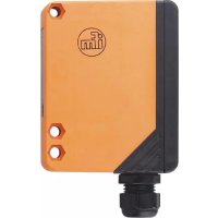
OA0123 - Motion detector IFM - Free user manual and instructions
Find the device manual for free OA0123 IFM in PDF.


| Product Type | Photoelectric barrier (non-contact motion detector) |
| Brand | IFM |
| Model | OA0123 |
| Range | See label (not specified in the manual) |
| Power Supply | 10–30 VDC (DC devices) |
| Power Consumption | Indicated by green LED (voltage OK) |
| Detection Type | Non-contact, by interruption of light beam |
| Output | Switched (transistor) with yellow LED for switching status |
| Diagnostic Output | 5 Hz signal in case of poor detection (dirt, misadjustment) |
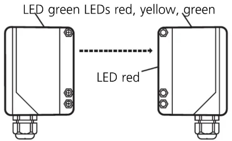
| Indicator LEDs | Green: voltage OK; Red (receiver): on if light received, flashes if poor reception; Yellow: output switched |
| Settings | Function selector (S1, S3): sensitivity, output function, timing (delay on activation/deactivation) |
| Timing | Configurable via selector: delay on rising/falling edge, resettable by pulse |
| Test Input (Emitter) | Disables light emission for test (DC devices) |
| Mounting | Receiver on mounting bracket; emitter oriented towards receiver |
| Electrical Connection | Strictly according to label; provide miniature fuse if specified |
| Warning | Disconnect installation before connection; check after short circuit |
| Maintenance | Clean lenses regularly to avoid dirt buildup |
| Repairability | Spare parts not specified; contact IFM or authorized dealer |
| Certifications | Not specified |
Frequently Asked Questions - OA0123 IFM
User questions about OA0123 IFM
0 question about this device. Answer the ones you know or ask your own.
Ask a new question about this device
Download the instructions for your Motion detector in PDF format for free! Find your manual OA0123 - IFM and take your electronic device back in hand. On this page are published all the documents necessary for the use of your device. OA0123 by IFM.
USER MANUAL OA0123 IFM
Through-beam sensor OA
Barrages
photoelectriques OA
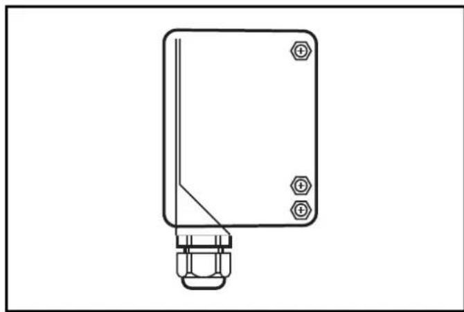
Functions and features
The through-beam sensor detects objects and materials without contact and indicates their presence by a switched signal.
Range: see type label.
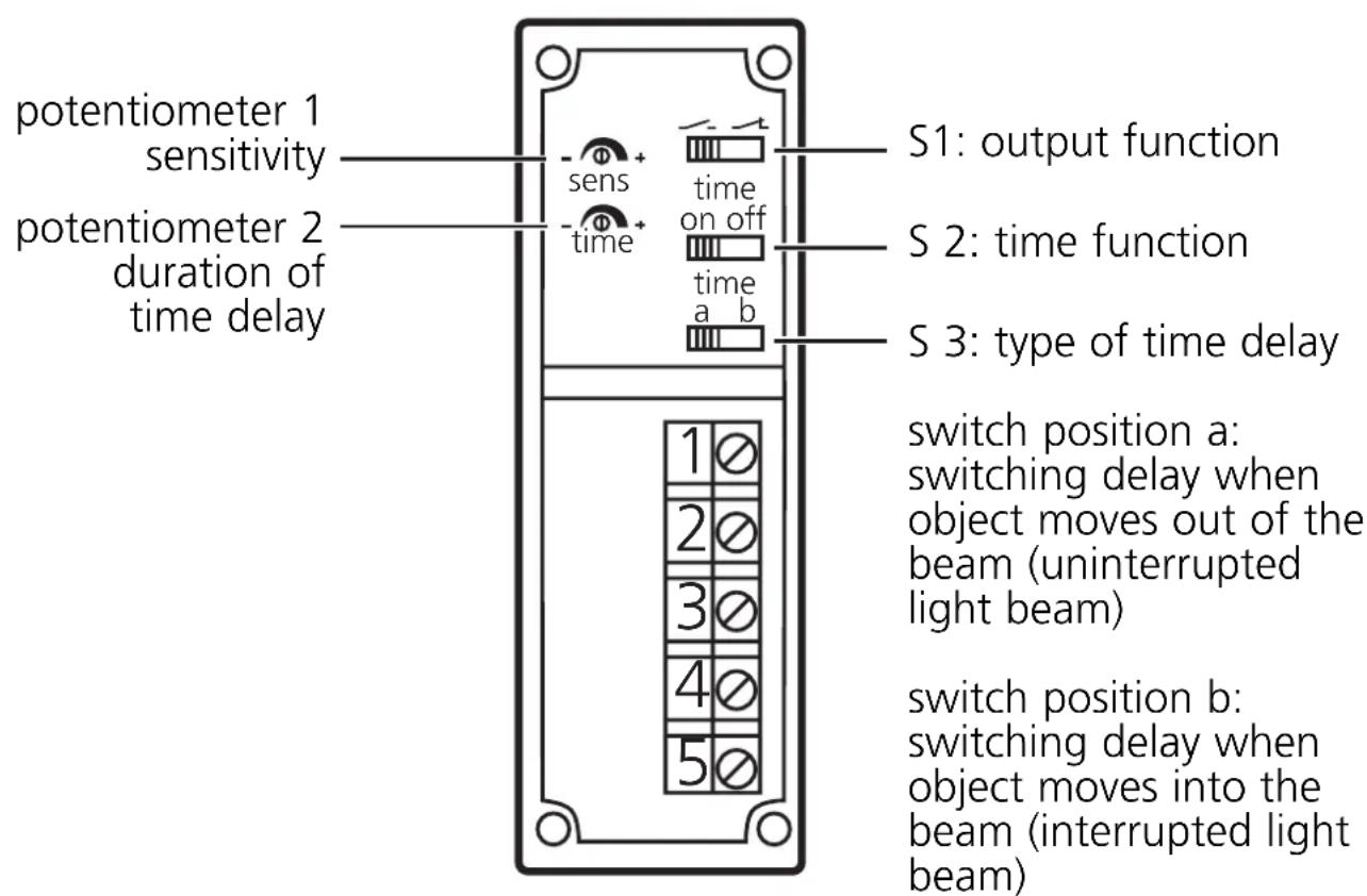
Controls and indicators
Electrical connection
Disconnect power before connecting the sensor.
Connection strictly to the indications on the type label.
Note: insert a miniature fuse according to the technical data sheet, if specified.
Recommendation: check the unit for reliable function after a short circuit
Installation
Fix the receiver (OAE...) in position.
Align the transmitter (OAS) towards the receiver and tighten in the same way.
Following electrical connection the transmitter can be set exactly by means of the LED display:
- The red LEDs of the receiver light if setting is exact.
- They flash if setting is inexact.
Maximum range only with precise alignment.
Test input of the transmitter (only for DC units)
By activating the test input (test at L-) the transmitter is deactivated. When no object is in the light beam between transmitter and receiver the LEDs indicating the reception of light must go off and the switching state of the output must change.
Setting
Set the sensitivity, the output function, the time function as well as the type and duration of the time delay.
Switch 3 = a
The signal "no object present" is transferred to the switching output after a delay.
- In the case of S1 = the output switches OFF after the falling edge + t.
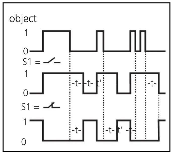
- In the case of S1 = the output switches ON after the falling edge + t.
A pulse during the time t triggers the timer again.
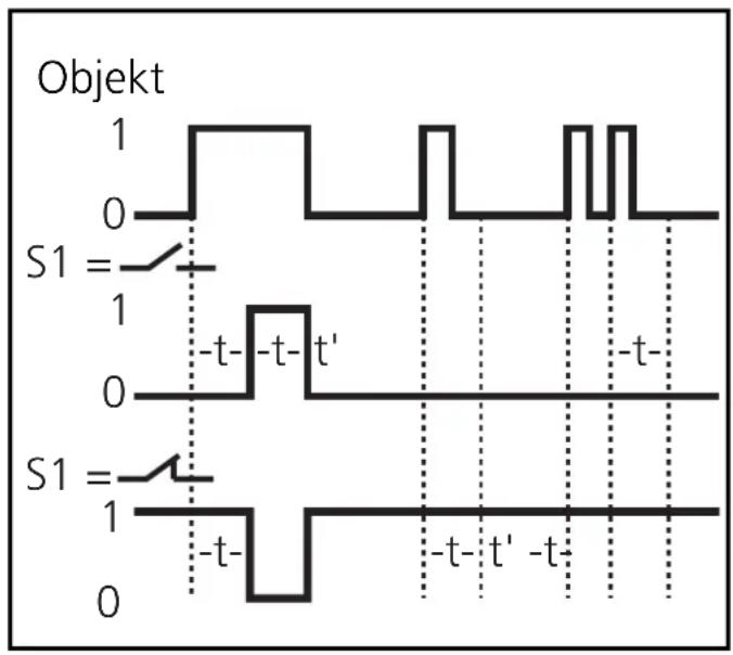
Switch 3 = b
The signal "object present" is transferred to the switching output after a delay.
In the case of S1 = the output switches ON after the rising edge + t.
In the case of S1 = the output switches OFF after the rising edge + t.
A pulse during the time t triggers the timer again.
Operation
Check the safe functioning of the through-beam sensor.
Display by LEDs and function check output.
- Green LEDs are lit = supply voltage o.k.
- Red LEDs are lit (receiver) = light reception (no object between transmitter and receiver).
- Red LEDs flashing = reception deteriorating (e.g. by soiling of the lenses or maladjustment).
- Yellow LED is lit = output switched.
The function check output indicates a wrong object detection (soiling of the lenses, maladjustment) by means of a 5 Hz signal.
When the object is again clearly detected, the output provides again a continuous signal.

Maintenance: Keep the lens of the sensor free from soiling.
Brand : IFM
Model : OA0123
Category : Motion detector