
KN0004 - Level sensor IFM - Free user manual and instructions
Find the device manual for free KN0004 IFM in PDF.

| Product type | Capacitive level sensor |
| Brand | IFM |
| Model | KN0004 |
| Detection type | Capacitive, for liquids and dry bulk materials (plastic granules) |
| Active face temperature | Up to 110 °C |
| Mounting | Non-contact (non-metallic tanks) or direct contact with fluid |
| Electrical connection | According to label; disconnect power before connection |
| Power supply | Not specified in manual; refer to product label |
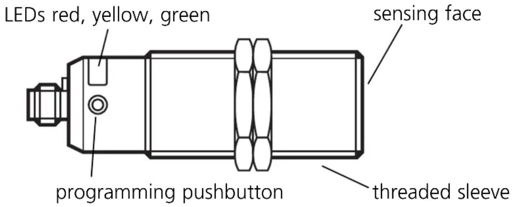
| LED indicators | Green, yellow, red LED for switching status, modes and errors |
| Main functions | Level detection, empty/full adjustment, NO/NC mode, automatic adjustment via push button |
| Programming | Via programming push button (non-sharp object) |
| Switching output | Normally open (NO) or normally closed (NC) configurable |
| Adjustments | Empty adjustment (empty tank), full adjustment (active zone covered), combined adjustment for optimal thresholds |
| Error messages | Red LED fast flashing (8 Hz): adjustment fault or internal fault; solution: repeat adjustment or cycle power |
| Maintenance and cleaning | No maintenance required; keep active face and surroundings free of deposits and foreign objects |
| Safety instructions | Disconnect power before any electrical connection |
| Warranty | Not mentioned; refer to IFM conditions |
Frequently Asked Questions - KN0004 IFM
User questions about KN0004 IFM
0 question about this device. Answer the ones you know or ask your own.
Ask a new question about this device
Download the instructions for your Level sensor in PDF format for free! Find your manual KN0004 - IFM and take your electronic device back in hand. On this page are published all the documents necessary for the use of your device. KN0004 by IFM.
USER MANUAL KN0004 IFM
Capacitive level sensor
natural_image
Technical line drawing of a mechanical component with no visible text or symbolsInhalt Seite
natural_image
Diagram of a micrometer measuring a granular liquid in a container (no text or symbols)natural_image
Diagram of a micrometer measuring a granular liquid in a container (no text or symbols)Medienberührend
natural_image
Technical line drawing of a mechanical device with a screwdriver inserted (no text or symbols)Programmieren
natural_image
Line drawing of a vintage camera with a screwdriver inserted (no text or symbols)Function and features 9
Mounting 10
Electrical connection 10
Operation 10
Programming 10
Set-up / Operation 14
Function and features
- Capacitive level switch for monitoring levels of liquids and dry bulk material, preferably plastic granulates.
- Automatic adjustment to the medium to be detected by means of programming pushbutton.
- The sensing face is rated for temperatures up to 110°C and can be mounted in direct contact with the sight glass (without air gap).
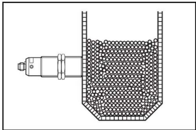
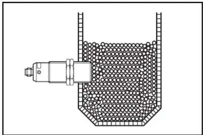
Mounting
Mount the level switch as shown:
natural_image
Diagram of a micrometer measuring a granular liquid in a container (no text or symbols)Not in contact with the medium (only for non-metallic tanks)
natural_image
Diagram of a mechanical device inside a container filled with spherical particles, no text or symbols presentIn contact with the medium
Electrical connection
Disconnect the installation from power. Connect the unit (see type label).
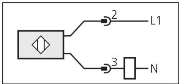
flowchart
graph TD
    A["Square Block"] --> B["AND Gate 2"]
    A --> C["AND Gate 3"]
    B --> D["L1"]
    C --> E["N"]
Operation
Adjust the sensor. To do so, press the programming pushbutton with a blunt object.
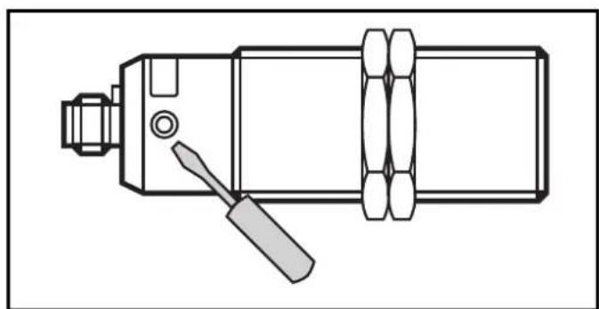
natural_image
Technical line drawing of a mechanical device with a screwdriver inserted (no text or symbols)Programming
Overview of the modes and their basic functions:
- Operating mode: Normal operating mode. In this mode all normal sensor functions are active.
- Adjustment mode: Setting of the switching threshold by empty and full adjustment.
- Normally closed/normally open mode (NO/NC mode): Change between normally closed and normally open function.
Empty adjustment
The unit must be adjusted after installation in the empty tank (empty adjustment). The tank can be considered to be "empty" when the medium to be detected is min. 20mm away from the active zone. If the sensor detects a medium after adjustment, its switching status changes.
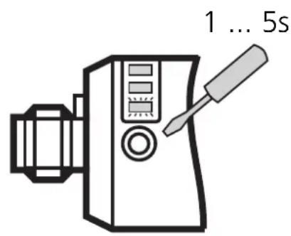
Press the programming pushbutton until the green LED flashes (for min.1s and max. 5s; unit is in the adjustment mode).
After adjustment - for the output function "normally open" - all LEDs are off. For the output function "normally closed" the yellow LED lights.
Note:
The sensor is operational just with empty adjustment. However, it is recommended to carry out a "full adjustment" with the active zone being completely covered after empty adjustment. On the basis of the values for the empty state/full state the internal microprocessor determines the optimum position of the switching thresholds between the two states. Using both adjustment criteria (empty and full adjustment) results in the maximum operational reliability for the application. For empty adjustment the internal microprocessor generates 2 values.
The first value corresponds to the sensor signal measured in the empty state. The second value is an assumed measured value for the full state. It is calculated from the just measured empty state and a factory signal preset. For full adjustment this second value is replaced by a real measured value.
Full adjustment
After empty adjustment the full state is to be achieved, if possible, so that the unit switches.
| 5 ... 10s | Press the programming pushbutton until the green LED flashes quickly(= unit is in the adjustment mode). |
 | The LED first flashes slowly (about 1 Hz), after 5s it flashes double as quickly (about 2 Hz).After adjustment - for the output function " normally open" - only the yellow LED lights. For the output function "normally closed" all LEDs are off. |
The full adjustment can be repeated as often as you like. The stored value for the empty state is not overwritten by the full adjustment. After a new empty adjustment both values are automatically set again, the values last defined are overwritten.

Therefore always carry out the empty adjustment first, then, if necessary, the full adjustment!
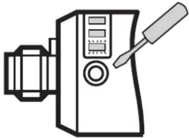
NO/NC mode:
The switching output of the unit can be operated as normally closed or normally open contact. To do so the unit must first be put in the NO/NC mode.
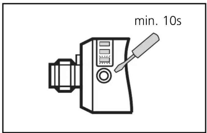
Activating the NO/NC mode:
Press the programming pushbutton for min. 10s.
The green LED first flashes slowly (about 1Hz), after 5s more quickly (about 2Hz), after 10s slowly again (about 1 Hz).
The unit now displays the current output function (normally closed or normally open):
- Normally open: green LED flashes slowly (about 1Hz)
- Normally closed: green and yellow LEDs flash alternately (about 1Hz)
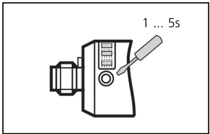
Changing the output function:
Press the programming pushbutton for min. 1s but not longer than 5s.
The change is immediately displayed by the LEDs after the programming pushbutton is released.
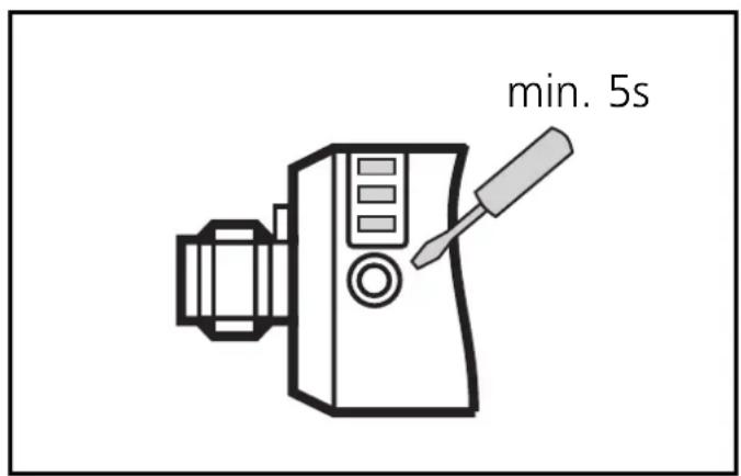
Deactivating the NO/NC mode:
Press the programming pushbutton in the NO/NC mode until the LEDs go out (min. 5s).
The unit is in the operating mode again. All normal sensor functions are active again.

After each programming operation the NO/NC mode must be deactivated.
If after the change into the NO/NC mode no operation is carried out for 30s the unit automatically changes back to the operating mode. The output function is not defined. Repeat the programming operation and then deactivate the NO/NC mode.
Note:
The switching function of the sensor is not active in the NO/NC mode. The output maintains the switching state which it had before switching on the NO/NC mode. The output stays virtually "frozen" until the NO/NC mode is deactivated again.
Error messages
If empty or full adjustment cannot be made, the red LED flashes quickly at about 8Hz after the adjustment attempt (adjustment error).
To delete this error message press the programming pushbutton once or power off and then power on again. The measured values successfully read so far remain unchanged.
Possible reasons for an error message:
- The signal difference between the empty and full state is too small (e.g. empty and full adjustment without sufficient change of the level).
- The signal change between the empty and full state is in the wrong order (e.g. empty adjustment in the full state and then full adjustment in the empty state).
- Empty adjustment outside the operating range (e.g. empty adjustment in case of direct contact with an electrically grounded medium, e.g. if the active zone is immersed in water).
Help: Avoid the above-mentioned errors and repeat the adjustment for error correction.
Further faults:
• Electronic fault or sensing zone of the unit damaged.
- Internal fault (can only be deleted by power off and then power on again, hardware reset).
Set-up/Operation
Check the safe functioning of the unit. To do so, bring about a sensor response by taking suitable measures.
Display by LEDs:
| LED green | • Flashes slowly (1Hz): adjustment mode empty state or NO/NC mode (output configured as normally open)• Flashes quickly (2Hz): adjustment mode full state• OFF: unit in the operating mode |
| LEDs green + yellow | • flash alternately (1Hz): NO/NC mode (output configured as normally closed) |
| LED yellow | • OFF: switching output disabled• ON: switching output enabled |
| LED red | • flashes quickly (8Hz): adjustment error, internal fault• flashes slowly (1Hz): close to reaching the switching threshold |
The red LED becomes active for a short time during the change between "medium not present" and "medium present" (flashes at 1Hz) if the medium is close to reaching the switching threshold. This can occur in particular if the level changes very slowly and is no error message meaning a fault in the unit.
The operation of the level switch is maintenance-free. For a correct function ensure:
- The sensing face and the open space should be kept free of deposits and foreign bodies, particularly for mounting with the sensing face showing upwards.
Contenu Page
natural_image
Diagram of a mechanical device with a granular material inside a container (no text or symbols)natural_image
Diagram of a mechanical device inside a container filled with spherical particles, no text or symbols presentnatural_image
Technical line drawing of a mechanical device with a screwdriver inserted (no text or symbols)Programmation


- Inhalt Seite
- Programmieren
- Function and features
- Mounting
- Electrical connection
- Operation
- Programming
- Empty adjustment
- Note:
- Full adjustment
- NO/NC mode:
- Activating the NO/NC mode:
- Changing the output function:
- Deactivating the NO/NC mode:
- After each programming operation the NO/NC mode must be deactivated.
- Error messages
- Set-up/Operation
- Contenu Page
- Programmation
Brand : IFM
Model : KN0004
Category : Level sensor