DMX Operator 192 - Controller Eurolite - Free user manual and instructions
Find the device manual for free DMX Operator 192 Eurolite in PDF.
| Product Type | DMX Controller |
| Brand | Eurolite |
| Model | DMX Operator 192 |
| Dimensions (L x W x H) | 483 x 132 x 80 mm |
| Minimum mounting depth | 170 mm |
| Weight | 2.5 kg |
| Power supply | 230 V AC, 50 Hz via power supply unit 9-12 V DC, 300 mA (included) |
| Power consumption | 4 W |
| Number of DMX channels | 192 (12 fixtures x 16 channels) |
| DMX output | XLR 3-pin connector |
| MIDI input | MIDI IN socket |
| Programs (Banks) | 16, up to 8 scenes each |
| Chasers | 6, up to 240 scenes each |
| Preset scenes | 8 |
| Sound control | Built-in microphone |
| Special functions | Blackout, Tap Sync, Manual programming, Copy/Delete scenes and programs, MIDI control |
| Rack mounting | 19", 3 units (U) |
| Operating temperature | -5°C to +45°C |
| Max. relative humidity | 50% at 45°C |
| Max. altitude | 2000 m |
| Maintenance | Clean with a damp, lint-free cloth, no alcohol or detergents |
| Repairability | Repairs by qualified technician only, original spare parts |
| Safety | Protect from moisture, disconnect before opening, indoor use only |
Frequently Asked Questions - DMX Operator 192 Eurolite
User questions about DMX Operator 192 Eurolite
0 question about this device. Answer the ones you know or ask your own.
Ask a new question about this device
Download the instructions for your Controller in PDF format for free! Find your manual DMX Operator 192 - Eurolite and take your electronic device back in hand. On this page are published all the documents necessary for the use of your device. DMX Operator 192 by Eurolite.
USER MANUAL DMX Operator 192 Eurolite
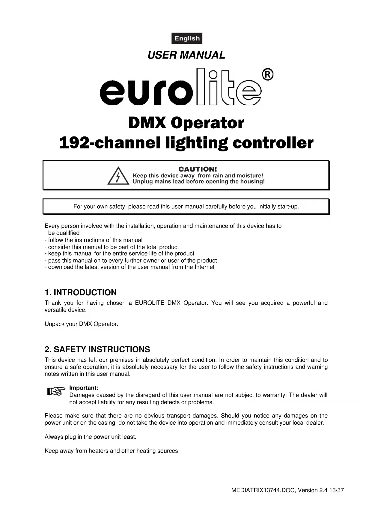
192-channel lighting controller
text_image
SCENES FRANKS Drip Programm 62880 Auto Vtgger Auto Vtgger SP - 100 Blackout Blue Programm 62880 CRASE 1 CRASE 2 CRASE 3 CRASE 4 CRASE 5 CRASE 6 CRASE 7 CRASE 8 CRASE 9 CRASE 10 CRASE 11 CRASE 12 CRASE 13 CRASE 14 CRASE 15 CRASE 16 PAGE A PAGE B DMX OPERATORMULTI-LANGUAGE-INSTRUCTIONS
5.1 Installation 16
5.2 Sound-control.... 16
5.3 DMX-512 connection with the projector 16
5.4 Connection of the Remote Switch socket 17
- OPERATION 17
6.1 Manual-mode 17
6.2 Programming....18
6.3 Chaser....18
6.4 Copying scenes, programs and records 19
6.5 Sound-control....19
6.6 MIDI-operation 20
- PROBLEM CHART 20
- CLEANING AND MAINTENANCE 20
- TECHNICAL SPECIFICATIONS....21
Français
-
INTRODUCTION 22
-
INSTRUCTIONS DE SÉCURITÉ ...... 22
-
EMPLOI SELON LES PRESCRIPTIONS....23
-
DESCRIPTION 24
This user manual is valid for the article numbers 70064520
You can find the latest update of this user manual in the Internet under:
text_image
1=Ground 2=Data 3=DATA+ STRONG 1/4" stereo jack Power supply: 0.12 V DC,0.34 m Power consumption: 4 W Type: CRR Counter Power supply: 0.12 V DC,0.34 m Power consumption: 4 W Rated output manual buttons with: Keep ready from measurement. Press open the control set out to be installed parts inside the device. Maintenance and service operations only by uncontrolled dealer. EURO REMOTE SWITCH The Sears - ring ring = 1.0V192-channel lighting controller
CAUTION!
Keep this device away from rain and moisture! Unplug mains lead before opening the housing!
For your own safety, please read this user manual carefully before you initially start-up.
Every person involved with the installation, operation and maintenance of this device has to
- be qualified
- follow the instructions of this manual
- consider this manual to be part of the total product
- keep this manual for the entire service life of the product
- pass this manual on to every further owner or user of the product
- download the latest version of the user manual from the Internet
1. INTRODUCTION
Thank you for having chosen a EUROLITE DMX Operator. You will see you acquired a powerful and versatile device.
Unpack your DMX Operator.
2. SAFETY INSTRUCTIONS
This device has left our premises in absolutely perfect condition. In order to maintain this condition and to ensure a safe operation, it is absolutely necessary for the user to follow the safety instructions and warning notes written in this user manual.

Important:
Damages caused by the disregard of this user manual are not subject to warranty. The dealer will not accept liability for any resulting defects or problems.
Please make sure that there are no obvious transport damages. Should you notice any damages on the power unit or on the casing, do not take the device into operation and immediately consult your local dealer.
Always plug in the power unit least.
Keep away from heaters and other heating sources!
English
If the device has been exposed to drastic temperature fluctuation (e.g. after transportation), do not switch it on immediately. The arising condensation water might damage your device. Leave the device switched off until it has reached room temperature.
This device falls under protection-class III. The device always has to be operated with an appropriate transformer.
Always disconnect from the mains, when the device is not in use or before cleaning it.
Please note that damages caused by manual modifications on the device or unauthorized operation by unqualified persons are not subject to warranty.
Keep away children and amateurs from the device!
There are no serviceable parts inside the device. Maintenance and service operations are only to be carried out by authorized dealers.
3. OPERATING DETERMINATIONS
This device is a DMX-controller for controlling DMX-effects or spots in discotheques, on stages etc. This product is allowed to be operated with a direct voltage of DC 9-12 V, 300 mA and was designed for indoor use only.
Do not shake the device. Avoid brute force when installing or operating the device.
When choosing the installation-spot, please make sure that the device is not exposed to extreme heat, moisture or dust. There should not be any cables lying around. You endanger your own and the safety of others!
This device must never be operated or stockpiled in sourroundings where splash water, rain, moisture or fog may harm the device. Moisture or very high humidity can reduce the insulation and lead to mortal electrical shocks. When using smoke machines, make sure that the device is never exposed to the direct smoke jet and is installed in a distance of 0.5 meters between smoke machine and device. The room must only be saturated with an amount of smoke that the visibility will always be more than 10 meters.
The ambient temperature must always be between -5^ C and +45^ C. Keep away from direct insulation (particularly in cars) and heaters.
The relative humidity must not exceed 50 % with an ambient temperature of 45^ C.
This device must only be operated in an altitude between -20 and 2000 m over NN.
Never use the device during thunderstorms. Over voltage could destroy the device. Always disconnect the device during thunderstorms.
Operate the device only after having familiarized with its functions. Do not permit operation by persons not qualified for operating the device. Most damages are the result of unprofessional operation!
Please use the original packaging if the device is to be transported.
Please consider that unauthorized modifications on the device are forbidden due to safety reasons!
Never remove the serial barcode from the device as this would make the guarantee void.
If this device will be operated in any way different to the one described in this manual, the product may suffer damages and the guarantee becomes void. Furthermore, any other operation may lead to dangers like short-circuit, burns, electric shock, etc.
4. DESCRIPTION
4.1 Features
Compact DMX-controller
• 192 control channel for 12 projectors with up to 16 channels
- 6 chaser with up to 240 scenes can be programmed
- 8 Preset Scenes
- Copy-function for the scenes, programs and records
- Blackout-function
• Sound control via built-in microphone
- Rack installation with 3 units
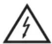
4.2 Overview
Overview on the control elements
flowchart
graph TD
    A["Scanners"] --> B["Flow"]
    B --> C["SCENES"]
    C --> D["Page A"]
    C --> E["Page B"]
    D --> F["DMX OPERATOR"]
    E --> F
    F --> G["10 MHz"]
    F --> H["30 MHz"]
    F --> I["60 MHz"]
    F --> J["80 MHz"]
    style A fill:#f9f,stroke:#333
    style B fill:#ccf,stroke:#333
    style C fill:#cfc,stroke:#333
    style D fill:#fcc,stroke:#333
    style E fill:#cff,stroke:#333
    style F fill:#ffc,stroke:#333
    style G fill:#fcf,stroke:#333
    style H fill:#cfc,stroke:#333
    style I fill:#cfc,stroke:#333
    style J fill:#cfc,stroke:#333
1) PROJECTOR SELECT BUTTONS
With the Projector select buttons you can choose the desired projector.
2) SCENE-BUTTONS
3) DISPLAY
4) CHANNEL FADERS
For adjusting the different DMX-values. The channels 1-8 can be adjusted directly after pressing the respective projector select button. The channels 9-16 can be adjusted after pressing the Page-button.
5) PAGE-BUTTON
In the manual mode, you can switch the channel faders from CH 1-8 to CH 9-16 by pressing the Page-button.
6) SPEED-FADER
7) FADE TIME-FADER
8) BANK-BUTTONS
9) CHASE-BUTTONS
10) PROGRAM-BUTTON
11) MIDI/ADD-BUTTON
12) AUTO/DEL-BUTTON
13) MUSIC/BANK-COPY-BUTTON
If this LED is on, the controller is in Audio-mode (operation with sound-control).
14) TAPSYNC DISPLAY-BUTTON
15) BLACKOUT-BUTTON
The Blackout-function closes the light output of all connected projectors via the shutter.
Rear panel:
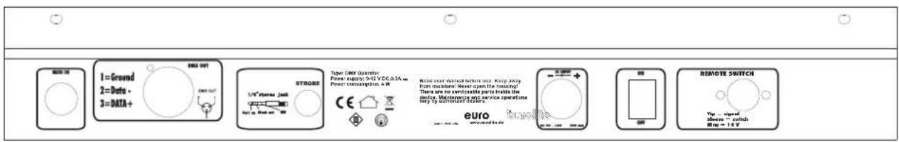
text_image
1=Ground 2=Data+ 3=DATA+ STROSE 1/4" Inverter: Joint Power Supply: 5V DC/ATA m Power consumption: + R Type: Case Operator Power supply: 5V DC/ATA m Power consumption: + R Real user trained before use. Keep X-ray From modules/ Rear open the baseing! There are no verifiable parts inside the device. Lowering test service operations only by unsecured power. EURO REMOTE SWITCH The closed Meets - catch Step = 1.5 VEnglish
Install the device on a plane surface or install it in rack.
This device is built for 483 mm racks (19"). This rack should be a double-door rack where front panel and rear panel can be opened. The rack should be provided with a cooling fan. When mounting the device into the rack, please make sure that there is enough space around the device so that the heated air can be passed on. Steady overheating will damage your device. You can fix the device with four screws M6 in the rack. If several devices are to be installed, make sure that you leave 1 unit (1 u) space between the devices. Connect the connection cable of the power-unit with the DC IN-socket. Plug the power unit into your outlet.
5.2 Sound-control
The sound-control works via the built-in microphone.
5.3 DMX-512 connection with the projector
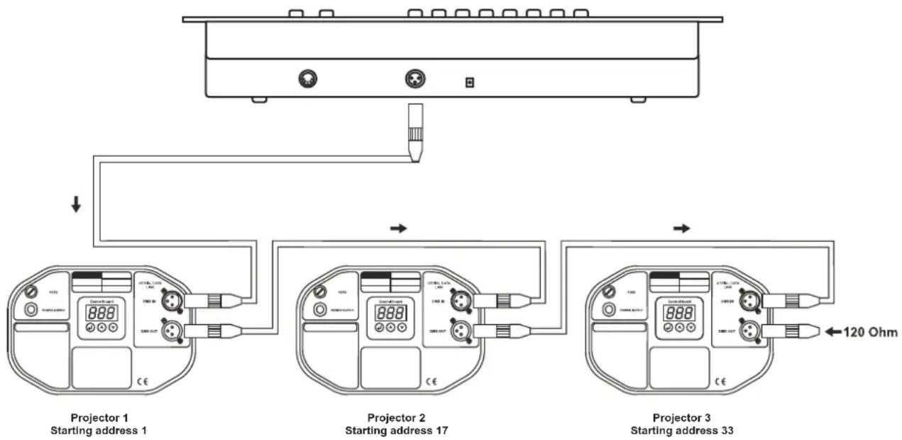
flowchart
graph TD
    A["Device"] --> B["Projector 1: Starting address 1"]
    A --> C["Projector 2: Starting address 17"]
    A --> D["Projector 3: Starting address 33"]
    B --> E["Control panel with 888/120 Ohm"]
    C --> F["Control panel with 120 Ohm"]
    D --> G["Control panel with 120 Ohm"]

The wires must not come into contact with each other, otherwise the fixtures will not work at all, or will not work properly.

Only use a stereo shielded cable and 3-pin XLR-plugs and connectors in order to connect the controller with the fixture or one fixture with another.
Building a serial DMX-chain:
Connect the DMX-output of the DMX Operator with the DMX-input of the nearest projector. Always connect one output with the input of the next fixture until all fixtures are connected.
Caution: At the last fixture, the DMX-cable has to be terminated with a terminator. Solder a 120 Ω resistor between Signal (−) and Signal (+) into a 3-pin XLR-plug and plug it in the DMX-output of the last fixture.
Projector addressing
Please note that the DMX Operator assigns the DMX-starting addresses every 16 steps. You have to
English
address every projector to the respective starting address. Otherwise, the channel assignment will not be correct. All projectors with the same starting address work synchronically.
| Projector | Starting address | Projector | Starting address | Projector | Starting address |
| Projector 1 1 | Projector 3 33 Projector 5 65 | ||||
| Projector 2 17 | Projector 4 49 Projector 6 81 | ||||
| Projector 7 97 | Projector 8 113 Projector 9 129 | ||||
| Projector 10 | 145 Projector 11 161 Projector 12 | 177 |
5.4 Connection of the Remote Switch socket
You can connect analogue-controlled devices, e. g. smoke-machines with low voltage connector to the Remote Switch socket.
This socket is only meant for low voltage!
The pin occupation of the stereo jack socket is as follows:
Tip = signal
Sleeve = switch
Ring = 10 V
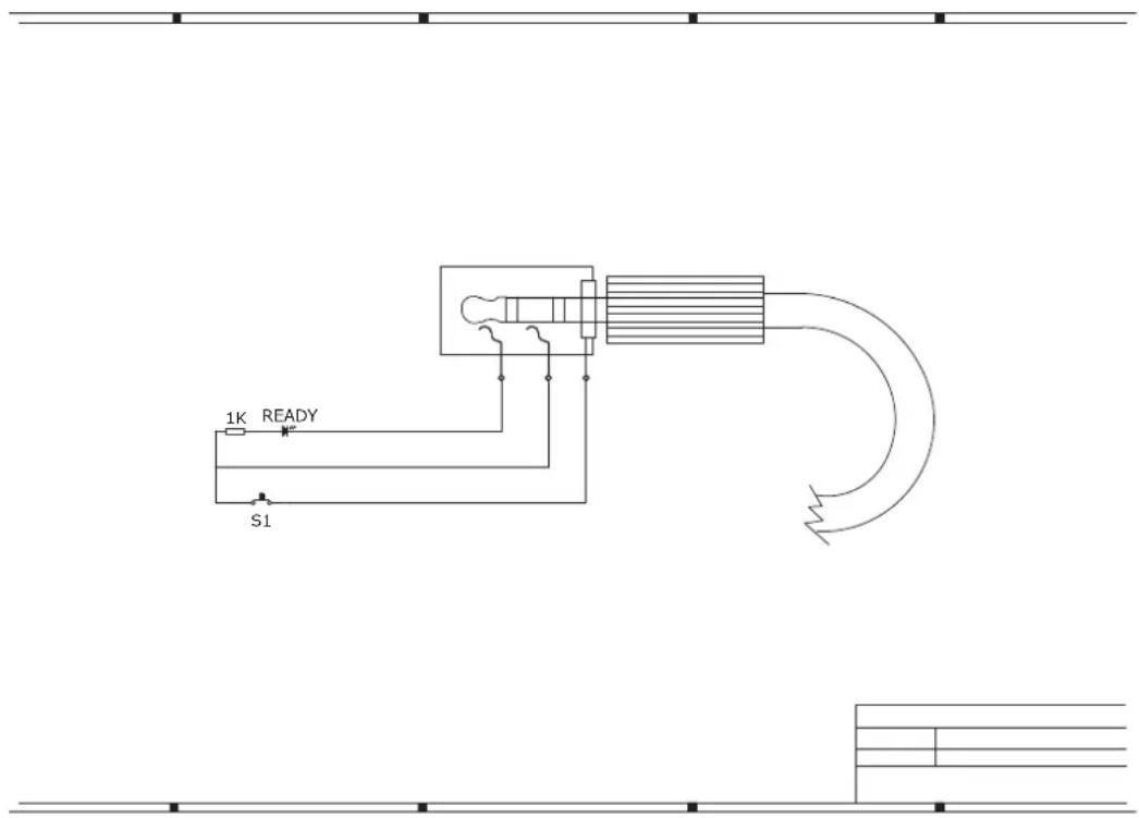
text_image
1K READY S16. OPERATION
After you connected the device to the mains, the DMX Operator is ready for use.
6.1 Manual-mode
6.1.1 Call up projectors manually
In the Manual-mode (Program-LED off), you can call up the connected projectors manually and control them via the channel faders. Please note that the adjusted settings cannot me memorized.
Select the desired projector via the respective projector select button.
Adjust the desired function via the channel faders.
Page Select-button:
Via the Page Select-button, you can adjust the channel faders from CH 1-8 to CH 9-16.
Display-button:
Via the Display-button, you can switch the faderway display from DMX-value (0-255) to procent (0-100).
6.2 Programming
A program is a sequence of different scenes that will be called up one after another. With the DMX Operator, you can program up to 30 different programs (banks) with up to 8 scenes each.
6.2.1 Programming a program
Press and hold the Program-button until the Program-LED flashes in the display. Select the desired program (bank) via the Bank-buttons.
Select the desired projector via the projector select buttons. Adjust the desired settings via the respective channel faders. Select the next projector via the projector select buttons and adjust the settings. Press the Add-button and then the respective Scene-button in order to save the first step. Program the next steps until the program is finished or the maximum number of steps - 8 - has been reached. Press the Program-button in order to save the program. The controller is now in the blackout-mode (Blackout-LED illuminated).
6.2.2 Running a program
Press the Bank-buttons and select the desired program. Press the Auto-button and the Auto Trigger LED is illuminated in the display. Adjust the program speed via the Speed-Fader and the repetition rate via the Fade Time-Fader.
As an alternative, you can adjust the program speed by tapping the Tapsynch-button twice. The time interval between the two taps corresponds to the program speed (up to 10 minutes).
6.2.3 Checking a program
Press and hold the Program-button and select the desired program via the Bank-buttons. Check every scene individually by pressing the respective Scene-button.
6.2.4 Editing a program
Should you notice that a scene does not correspond to your imagination or when programs have to be edited for a new stage, it is necessary to modify a scene manually.
Press and hold the Program-button and select the desired program via the Bank-buttons.
Select the desired scene via the scene button. Select the desired projector via the projector select buttons. Adjust the desired settings via the respective channel faders. Select the next projector via the projector select buttons and adjust the settings. Press the Add-button and the respective Scene-button in order to save the edited step. Edit the next steps until the program is finished.
6.3 Chaser
A chaser is a sequence of different programs that will be called up one after another. With the DMX Operator, you can program up to 6 different chasers with up to 240 steps.
6.3.1 Programming a chaser
Press and hold the Program-button. Select the desired chaser via the Chase-buttons.
Select the desired program via the Bank-buttons. Select the desired scene via the Scene-buttons. Press the Add-button. Program the next steps until the chaser is finished or the maximum number of steps - 240 - has been reached. Press and hold the Program-button in order to save the chaser.
Copying a bank into a chaser
As an alternative, you can copy a whole bank (with up to 8 scenes) into a chaser. Select the desired program via the Bank-buttons. Press the Bank Copy-button and the Add-button.
6.3.2 Running a chaser
Press the respective Chaser-button and press the Auto-button. You can adjust the chaser speed by tapping the Tapsynch-button twice. The time interval between the two taps corresponds to the chaser speed (up to 10 minutes).
Press the Record-button and select the desired record via the projector select buttons.
6.3.3 Checking a chaser
Press and hold the Program-button and select the desired chaser via the Chase-buttons. Press the Display-button in order to switch the display to step. Check every scene individually by pressing the respective Bank-button.
English
6.3.4 Editing a chaser
Insert step
Press and hold the Program-button. Select the desired chaser via the Chase-buttons. Press the Display-button in order to switch the display to step. Press the respective Bank-button in order to select the scene where the steps is to be inserted.
Press the Add-button. Select the desired scene via the Bank-buttons and the respective Scene-button. Press the Add-button once more.
Delete step
Press and hold the Program-button. Select the desired chaser via the Chase-buttons. Press the Display-button in order to switch the display to step. Press the respective Bank-buttons in order to select the scene which is to be deleted. Press the Del-button.
Press and hold the Program-button in order to save the edited chaser.
6.3.5 Delete a chaser
Press and hold the Program-button. Select the desired chaser via the Chase-buttons. Press and hold the Del-button and press the Chase-button.
6.3.6 Delete all chasers
Caution: When you select this function, all programmed chaser will irrevocably be lost. The individual scenes and programs are still maintained.
Press and hold the Bank Down-button and the Del-button while disconnecting the device from the mains.
Connect the device to the mains again.
6.4 Copying scenes, programs and records
With the Copy-function, you can make programming of programs and chasers easier by copying already existent scenes into a program.
Copy a scene
Press and hold the Program-button and select the desired program via the Bank-buttons. Press the respective Scene-button. Press the Add-button and select the desired bank where you want to copy the scene to. Press the desired Scene-button.
Delete a scene
Press and hold the Program-button and select the desired program via the Bank-buttons. Press the respective Scene-button. Press and hold the Del-button and press the desired Scene-button. The DMX-value of this scene is set to 0.
Copy a program
Press and hold the Program-button and select the desired program via the Bank-buttons. Press the Add-button and select the desired bank where you wish to copy the program to. Press the Bank Copy-button.
Delete a program
Press and hold the Program-button and select the desired program via the Bank-buttons. Press and hold the Del-button and press the Bank Copy-button.
Delete all scenes
Caution: When you select this function, all programmed scenes will be irrevocably lost!
Press and hold the Program-button and the Bank Down-button while disconnecting the device from the mains. Connect the device to the mains again.
6.5 Sound-control
You can activate the sound-control by pressing the Music-button (LED flashes). Please note that programs and records are only active in this mode when the controller receives a music-signal. If there is no music present, the program or chaser stops.
English
6.6 MIDI-operation
Press the MIDI-button and the third and fourth digit in the display start flashing. Select the respective MIDI-channel via the Bank-buttons. Press the MIDI-button again in order to terminate the adjustment of the MIDI-channels.
Overview on the MIDI-functions:
| Bank | Note-number | Function | e-number | Function | ||
| Bank 1 | 00 | Scene 1 | Bank | 15 | 112 Scene 1 | |
| 01 | Scene 2 | Bank | 15 | 113 Scene 2 | ||
| 02 | Scene 3 | Bank | 15 | 114 Scene 3 | ||
| 03 | Scene 4 | Bank | 15 | 115 Scene 4 | ||
| 04 | Scene 5 | Bank | 15 | 116 Scene 5 | ||
| 05 | Scene 6 | Bank | 15 | 117 Scene 6 | ||
| 06 | Scene 7 | Bank | 15 | 118 Scene 7 | ||
| 07 | Scene 8 | Bank | 15 | 119 Scene 8 | ||
| Bank 2 | 08 | Scene 1 | Chase | 120 Chase 1 | ||
| 09 | Scene 2 | Chase | 121 Chase 2 | |||
| 10 | Scene 3 | Chase | 122 Chase 3 | |||
| ... | ... | Chase | 123 Chase 4 | |||
| Chase | 124 | Chase 5 | ||||
| Chase | 125 | Chase 6 | ||||
| Chase | 126 | Blackout | ||||
7. PROBLEM CHART
| PROBLEM | CAUSE | REMEDY |
| No power. | The power unit is not connected. | Check the connection cable of the power unit and any extension-cables. |
| No signal output. | Blackout-mode activated. | Switch off blackout by pressing the Blackout-button. |
8. CLEANING AND MAINTENANCE
DANGER TO LIFE!
Disconnect from mains before starting maintenance operation!
We recommend a frequent cleaning of the device. Please use a soft lint-free and moistened cloth. Never use alcohol or solvents!
There are no servicable parts inside the device. Maintenance and service operations are only to be carried out by authorized dealers.
Should you need any spare parts, please use genuine parts.
Should you have further questions, please contact your dealer.
9. TECHNICAL SPECIFICATIONS
| Power supply: 230 V AC, 50 Hz ~ | |
| via 9-12 V DC, 300 mA power unit included in the delivery | |
| Power consumption: 4 W | |
| Number of control channels: 192 | |
| Sound-control: via built-in microphone | |
| DMX512 output: 3-pin XLR connector | |
| Free chasers: 6 x 240 scenes | |
| Dimensions (LxWxH): 483 x 132 x 80 mm | |
| Rack installation with 3 u | |
| Minimum mounting depth: 170 mm | |
| Weight: | 2.5 kg |
| Accessory: | |
| Mixer case Pro MCB-19, sloping, black 8U No. 30111560 | |
| Mixer case Pro MCB-19, sloping, alu 8U No. 30111564 | |
| Cable MC-100, 10m,black,XLR m/f,balanced No. 3022055N | |
| DMX terminator DES-3 DMX 3-pin | No. 51834001 |
Please note: Every information is subject to change without prior notice. 04.10.2011 ©
eurolite® GERMANY
MODE D'EMPLOI
eurolite®
DMX Operator
flowchart
graph TD
    A["Device"] --> B["Projector 1: Starting address 1"]
    A --> C["Projector 2: Starting address 17"]
    A --> D["Projector 3: Starting address 33"]
    B --> E["Current meter connected to terminal block"]
    C --> F["Current meter connected to terminal block"]
    D --> G["Current meter connected to terminal block"]
    E --> H["120 Ohm current"]
    F --> I["120 Ohm current"]
    G --> J["120 Ohm current"]