
SandMaster SM2506T - Water filter HAYWARD - Free user manual and instructions
Find the device manual for free SandMaster SM2506T HAYWARD in PDF.
| Brand | Hayward |
| Model | SandMaster SM2506T |
| Product Type | High-Flow Sand Filter |
| Effective Filtration Area | 3.14 ft² (0.29 m²) |
| Rated Flow Rate | 63 GPM (238 L/min) |
| Maximum Working Pressure | 50 psi (3.45 bar) |
| Side Clearance | 18 in (45 cm) |
| Top Clearance | 18 in (45 cm) |
| Required Material (Sand) | 0.45 - 0.55 mm (#20 silica sand) |
| Sand Quantity | 136 kg (300 lb) |
| Valve Type | 6-Position Vari-Flo (Filter, Backwash, Rinse, Waste, Recirculate, Closed) |
| Tank Material | Anti-corrosion (resin or high-density polyethylene) |
| Functions | Filtration, backwash, rinse, waste drainage, recirculation, shut-off |
| Maintenance | Backwash when pressure increases 8-10 psi (4-6 bar) above initial pressure |
| Winterizing | Drain tank, unscrew drain plug, set valve to neutral position |
| Safety | Always stop pump before changing valve position |
| Replacement Parts | Pressure gauge (EC-2708-1), O-ring (GM-600-F), collar clamp (GM-600-NM), laterals (S-200-Q), drain plug (S-180-LM) |
| Repairability | Contact Hayward authorized service center |
| Warranty | See manual or dealer |
Frequently Asked Questions - SandMaster SM2506T HAYWARD
User questions about SandMaster SM2506T HAYWARD
0 question about this device. Answer the ones you know or ask your own.
Ask a new question about this device
Download the instructions for your Water filter in PDF format for free! Find your manual SandMaster SM2506T - HAYWARD and take your electronic device back in hand. On this page are published all the documents necessary for the use of your device. SandMaster SM2506T by HAYWARD.
USER MANUAL SandMaster SM2506T HAYWARD
Your Sandmaster high rate sand filter is a high performance totally corrosion-proof filter that blends superior flow characteristics and features with ease of operation. It represents the very latest in high rate sand filter technology. It is virtually foolproof in design and operation and when installed, operated and maintained according to instructions, your filter will produce clear, sparkling water with only the least attention and care.
HOW IT WORKS
The Sandmaster uses special filter sand to remove dirt particles from pool water. Sand is loaded into the filter tank and functions as the permanent dirt removing media. The pool water, which contains suspended dirt particles, is pumped through your piping system and is automatically directed by the patented filter control valve to the top of the filter tank. As the pool water is pumped through the filter sand, dirt particles are trapped by the sand bed, and filtered out. The cleaned pool water is returned from the bottom of the filter tank, through the control valve and back to the pool through the piping system. This entire sequence is continuous and automatic and provides for total recirculation of pool water through your filter and piping system. After a period of time the accumulated dirt in the filter causes a resistance to flow, and the flow diminishes. This means it is time to clean (backwash) your filter. With the control valve in the backwash position, the water flow is automatically reversed through the filter so that it is directed to the bottom of the tank, up through the sand, flushing the previously trapped dirt and debris out of the waste line. Once the filter is backwashed (cleaned) of dirt, the control valve is manually resequenced to Rinse, and then Filter, to resume normal filtering.
INSTALLATION
Only simple tools (screwdriver and wrenches), plus pipe sealant for plastic adapters, are required to install and/or service the filter.
-
The filter system should be placed on level, very firm ground, or equivalent, as recommended by your pool dealer. Position the filter so that the piping connections, control valve and winter drain are convenient and accessible for operation, servicing and winterizing.
-
Assemble the Pump to the platform base. The flexible hose and adapters must now be installed to connect the pump/filter system.
a. Screw straight adapter, using Teflon pipe sealant tape or Permatex No. 2, securely into 1 1/2" pump discharge.
b. Screw other straight adapter, using Teflon pipe sealant tape or Permatex No. 2, securely into opening in control valve marked PUMP. (Do not overtighten.)
STOP here and load media per instructions (No. 3).
c. Place hose clamps on hose and fit hose over straight adapters and secure with clamps. If hose is difficult to fit over adapters, place hose in hot water for several minutes.
NOTE: To prevent breakage and damage to pump and control valve, use only pipe sealants specifically formulated for plastics. Do not overtighten fittings or adapters.
SPECIFICATIONS
| MODEL NO. | EFFECTIVE FILTRATION AREA | DESIGN FLOW RATE | MAXIMUM WORKING PRESSURE | ABOVE CLEARANCES | DE CLEARANCEA REQUIRED | ||||||||
| FT2 | M2 | GPM | LPM | PSI | BAR | INCH | CM | INCH | CM | TYPE | LBS | KG | |
| SM1706T | 1.50 | 0.14 | 38 | 144 | 50 | 3.45 | 18 | 45 | 18 | 45 | .45 mm -.55 mmNo 20 or No 1/2Silica Filter Sand | 125 | 57 |
| SM1906T | 1.80 | 0.17 | 40 | 151 | 50 | 3.45 | 18 | 45 | 18 | 45 | 175 | 80 | |
| SM2106T | 2.20 | 0.20 | 44 | 161 | 50 | 3.45 | 18 | 45 | 18 | 45 | 225 | 100 | |
| SM2306T | 2.64 | 0.25 | 53 | 200 | 50 | 3.45 | 18 | 45 | 18 | 45 | 250 | 114 | |
| SM2506T | 3.14 | 0.29 | 63 | 238 | 50 | 3.45 | 18 | 45 | 18 | 45 | 300 | 136 | |
| REF. NO. | PART NO. | DESCRIPTION | NO. REQ'D. |
| 1 | SP-0714TC | Vari-Flo Control Valve 6-Position | 1 |
| 2 | EC-2708-1 | Pressure Gauge | 1 |
| 3 | GM-600-F | Valve/Tank O-Ring | 1 |
| 4 | GM-600-NM | Flange Clamp (Valve Tank) | 1 |
| 5a | S-170-DA | Lateral Assy. (SM1706T) | 1 |
| 5b | S-180-DA | Lateral Assy. (SM1906T) | 1 |
| 5c | S-210-DA | Lateral Assy. (SM2106T) | 1 |
| 5d | S-220-DA | Lateral Assy. (SM2306T) | 1 |
| 5e | S-244-DA | Lateral Assy. (SM2506T) | 1 |
| 6a | DP-10298-B | Filter Tank (SM1706T) | 1 |
| 6b | S-180-AB | Filter Tank (SM1906T) | 1 |
| 6c | S-210-AB | Filter Tank (SM2106T) | 1 |
| 6d | S-220-AB | Filter Tank (SM2306T) | 1 |
| 6e | S-244-AB | Filter Tank (SM2506T) | 1 |
| 7 | S-200-Q | Lateral | 10 |
| 8 | S-180-LM | Drain Cap & Gasket | 1 |
| 9a | S-164-B | Base (SM1706T) | 1 |
| 9b | S-200-J | Base (SM2306T, SM1906T, SM2106T & SM2506T) | 1 |
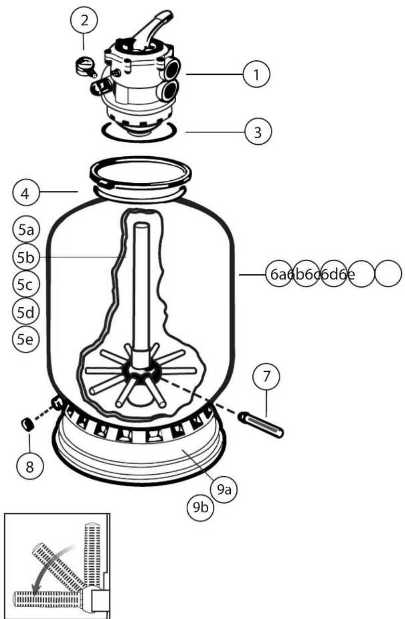
Figure A
- Loading sand media. Filter sand media is loaded through the top opening of the filter.
a. Loosen flange clamp and remove Filter Control Valve (if previously installed).
b. Cap internal pipe with plastic cap to prevent sand from entering it. Be sure pipe is securely in place in bottom underdrain hub.
c. We recommend filling tank approximately 1/2 way with water to provide a cushioning effect when the filter sand is poured in. This helps protect the under-drain laterals from excessive shock. (Be sure the winter drain cap is securely in place on drain pipe.) Note: Please check to confirm all laterals are in the down position before loading with sand. See figure A.
d. Slowly pour in correct amount and grade of filter sand, as specified. (Be sure center pipe remains centered in opening.) Sand surface should be leveled and should come to about the middle of the filter tank. Remove plastic cap from internal pipe.
- Assemble Filter Control Valve to filter tank.
a. Place stainless steel valve flange clamp around neck of tank. Do not tighten. Wipe filter flange clean.
b. Insert Filter Control Valve (with valve/flange o-ring in place) into the tank neck, taking care that the center pipe slips into the hole in the bottom of the valve. Place clamp around valve flange and tank flange and tighten just enough so that the valve may be rotated on tank for final positioning.
c. Carefully screw pressure gauge, with pipe tape, into 1/4 tapped hole in valve body. Do not overtighten.
d. Connect pump to control valve opening marked PUMP according to instructions. After connections are made, tighten valve flange clamp with screwdriver, tapping around clamp with screwdriver handle to help seat valve flange clamp.
-
Make return to pool pipe connection to control valve opening marked RETURN and complete other necessary plumbing connections, suction lines to pump, waste, etc.
-
Make electrical connections to pump per pump instructions.
-
To prevent water leakage, be sure winter drain cap is securely in place and all pipe connections are tight.
INITIAL START UP OF FILTER
- Be sure correct amount of filter sand media is in tank and that all connections have been made and are secure.
- Depress Vari-Flo control valve handle and rotate to BACKWASH position. (To prevent damage to control valve seal, always depress handle before turning.)
-
Prime and start pump according to pump instructions (be sure all suction and return lines are open), allowing the filter tank to fill with water. Once water flow is steady out the waste line, run the pump for at least 2 minutes. The initial backwashing of the filter is recommended to remove any impurities or fine sand particles in the sand media.
-
Turn pump off and set valve to RINSE position. Start pump and operate until water in sight glass is clear - about 1/2 to 1 minute. Turn pump off and set valve to FILTER position and restart pump. Your filter is now operating in the normal filter mode, filtering particles from the pool water.
- Adjust pool suction and return valves to achieve desired flow. Check system and filter for water leaks and tighten connections, bolts, nuts, as required.
- Note the initial pressure gauge reading when the filter is clean. (It will vary from pool to pool depending upon the pump and general piping system.) As the filter removes dirt and impurities from the pool water, the accumulation in the filter will cause the pressure to rise and flow to diminish. When the pressure gauge reading is 8-10 lbs. (4-6 BAR) higher than the initial "clean" pressure you noted, it is time to backwash (clean) the filter (see BACKWASH under Filter and Control Valve Functions).
NOTE: During initial clean-up of the pool water it may be necessary to backwash frequently due to the unusually heavy initial dirt load in the water.
CAUTION: To prevent unnecessary strain on piping system and valving, always shut off pump before switching Filter Control Valve Functions positions.
To prevent damage to the pump and filter and for proper operation of the system, clean pump strainer and skimmer baskets regularly.
FILTER AND CONTROL VALVE FUNCTIONS
FILTER - Set valve to FILTER for normal filtering. Also use regular vacuuming.
BACKWASH - For cleaning filter. When filter pressure gauge rises 8-10 lbs. (4-6 BAR) above start-up (clean pressure): Stop the pump, set valve to BACKWASH. Start pump and backwash until waste water is clear. Approximately 2 minutes or less depending on dirt accumulation. Proceed to RINSE.
RINSE - After backwashing, with pump off, set valve to RINSE. Start pump and operated for about 1/2 to 1 minute. This assures that all dirty water from backwashing is rinsed out of the filter to waste, preventing possible return to the pool. Stop pump, set valve to FILTER, and start pump for normal filtering.
WASTE - To bypass filter for draining or lowering water level and for vacuuming heavy debris directly to waste.
RECIRCULATE - Water is recirculated through the pool system by-passing the filter.
CLOSED - Shuts off flow from pump to filter.
VACUUMING - Vacuuming can be performed directly into the filter. When vacuuming heavy debris loads, set valve to WASTE position to bypass the filter and vacuum directly out to waste.
*NOTE: For new concrete or gunite pools, or where there is a large amount of plaster dust or debris - start filter in FILTER position (not BACKWASH) to prevent clogging of underdrain laterals.
WINTERIZING
- Completely drain tank by unscrewing drain cap at base of filter. Leave drain cap off for the duration of the winter months.
-
Depress Vari-Flo control valve handle and rotate so as to set valve pointer on valve top between any position. This will allow water to drain from the valve. Leave valve in this "inactive" position.
-
ALL MOTORS AND PUMPS - Off season, motor should be stored indoors in a warm, dry place. Motors left outdoors should not be tightly wrapped with plastic, as moisture will be trapped, resulting in condensation and damage to the motor.
SERVICE & REPAIRS
Consult your local authorized Hayward dealer or service center. No returns may be made directly to the factory without the express written authorization of Hayward Pool Products, Canada, Inc.
PLEASE REALIZE...
Pure, clear swimming pool water is a combination of two factors - adequate filtration and proper water chemistry balance. One without the other will not give the clean water you desire. Your filter system is designed for continuous operation. However, this is not necessary for most swimming pools. You can determine your filter operation schedule based on your pool size and usage. Be sure
to operate your filtration system long enough each day to obtain at least one complete turnover of your pool water. To properly sanitize your pool, maintain a free chlorine level of 1 to 2 ppm and a pH range of 7.2 to 7.6. Insufficient chlorine or an out of balance pH level will permit algae and bacteria to grow in your pool and make it difficult for your filter to properly clean the pool water.
PROBLEM SOLVING LIST
| REMEDY | LOW WATER FLOW | FILTER SHORT CYCLES | POOL WATER WON'T CLEAR UP |
| 1. Check skimmer and pump strainer baskets for debris.2. Check for restrictions in intake and discharge lines.3. Check for air leak in intake line (indicated by bubbles returning to pool).4. Backwash filter. | 1. Check for algae in pool and superchlorinate as required.2. Be sure chlorine and pH levels are in proper range (adjust as required).3. Check surface of filter sand for crusting or caking (remove 1" of sand if necessary). | 1. Check chlorine, pH and total alkalinity levels and adjust as required.2. Be sure flow rate through filter is sufficient.3. Operate filter for longer periods.4. Be sure control valve is set on "Filter" position. |
POOL CHEMISTRY GUIDELINES
| SUGGESTED POOL CHEMISTRY LEVELS | ACTION REQUIRED TO CORRECTED POOL CHEMISTRY | ||
| TO RAISE | TO LOWER | ||
| pH | 7.2 to 7.6 | Add Soda Ash | Add Muriatic Acid or Sodium Bisulphate |
| TOTAL ALKALINITY | 100 to 130 ppm | Add Sodium Bicarbonate | Add Muriatic Acid |
| CHLORINE (UNSTABILIZED) | 0.3 to 1.0 ppm | Add Chlorine Chemical | No action - chlorine will naturally dissipate |
| CHLORINE (STABILIZED) | 1.0 to 3.0 ppm | Add Chlorine Chemical | No action - chlorine will naturally dissipate |
| CHLORINE STABILIZER (Cyanuric Acid) | 40 to 70 ppm | Add Stabilizer | Dilution - partially drain & refill pool with water that has not been treated with Cyranuric Acid. |
MANUFACTURED EXCLUSIVELY BY HAYWARD
2880 PLYMOUTH DRIVE, OAKVILLE, ONTARIO L6H 5R4 1-888-238-7665
Sand MASTER
MANUFACTURÉ EXCLUSIVEMENT PAR HAYWARD
2880 PLYMOUTH DRIVE, OAKVILLE, ONTARIO L6H 5R4 • TÉL. 1-888-238-7665
Brand : HAYWARD
Model : SandMaster SM2506T
Category : Water filter