
Classic Heat Pump - Heating HAYWARD - Free user manual and instructions
Find the device manual for free Classic Heat Pump HAYWARD in PDF.

| Product type | Pool heat pump |
| Brand | Hayward |
| Model | Classic Heat Pump (HP50CL, HP65CL, HP80CL) |
| Dimensions (L × W × H) | HP50CL : 1049 × 455 × 658 mm ; HP65CL : 956 × 360 × 600 mm ; HP80CL : 1115 × 450 × 868 mm |
| Power supply | 208-230 V ~ / 60 Hz, single phase |
| Rated current | 12 A (HP50CL), 15.5 A (HP65CL), 17.5 A (HP80CL) |
| Refrigerant | R410A |
| Heating input power | 2.68 kW (HP50CL), 3.2 kW (HP65CL), 3.6 kW (HP80CL) |
| Recommended water flow | 4.5 m³/h (19.8 gpm) for HP50CL and HP65CL ; 8.18 m³/h (36 gpm) for HP80CL |
| Water connection | 1.5 inch (PVC thread) |
| Noise level | 54 dB(A) (HP50CL), 56 dB(A) (HP65CL and HP80CL) |
| Compressor | Rotary Scroll (HP65CL, HP80CL) or rotary (HP50CL) |
| Number of fans | 1 |
| Operating modes | Heating, cooling (depending on model), automatic |
| Set temperature range | Not specified in the manual, adjustable via the control system |
| Heat exchanger | Titanium and PVC tubes, resistant to pool water |
| Routine maintenance | Regular cleaning of the pool filter and finned heat exchanger ; checking electrical connections |
| Winterization | Drain all water from the unit, disconnect connections, protect against frost |
| Safety protections | High pressure, low pressure, flow sensor, frost protection, mandatory grounding |
| Warranty | 1 year parts and labor, compressor 2 years, titanium heat exchanger 5 years |
| Available spare parts | Compressor, fan, heat exchanger, electronic boards, sensors, contactors, etc. |
Frequently Asked Questions - Classic Heat Pump HAYWARD
User questions about Classic Heat Pump HAYWARD
0 question about this device. Answer the ones you know or ask your own.
Ask a new question about this device
Download the instructions for your Heating in PDF format for free! Find your manual Classic Heat Pump - HAYWARD and take your electronic device back in hand. On this page are published all the documents necessary for the use of your device. Classic Heat Pump by HAYWARD.
USER MANUAL Classic Heat Pump HAYWARD
natural_image
Abstract geometric logo with a white circle containing black squares and a central 'H' shape, no text or symbols present.HAYWARD®
SWIMMING POOL HEAT PUMP UNIT
Installation & Instruction Manual
Model
HP50CL
HP65CL
HP80CL
natural_image
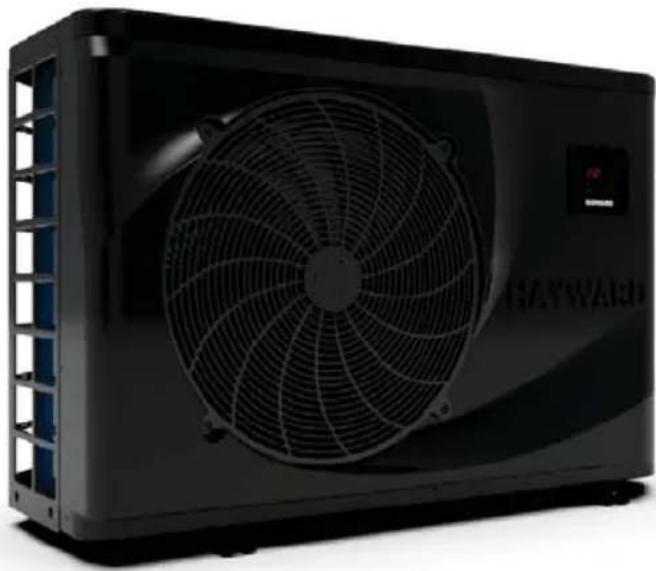
Exterior view of a black Hayward air conditioning unit with a circular fan and control panel (no visible text or symbols)1. Preface 1
2. Specifications 2
2.1 Performance Data of Swimming Pool Heat Pump Unit 2
2.2 Dimensions for Swimming Pool Heat Pump Unit 3
3. Installation and Connection 6
3.1 Installation of System 6
3.2 Swimming Pool Heat Pumps Location 7
3.3 How Close to Your Pool? 7
3.4 Swimming Pool Heat Pumps Plumbing 8
3.5 Swimming Pool Heat Pumps Electrical Wiring 9
3.6 Initial Start-up of the Unit 9
4. Usage and Operation 10
4.1 Function of the controller 10
4.2 Usage of the controller 11
4.3 Parameter table 13
4.4 Mulfunction table 14
5. Maintenance and Inspection 15
5.1 Maintenance and inspection 15
5.2 Winterization 15
6. Appendix
6.1 Connection of PCB: Illustration 16
6.2 Wiring Diagram 17
6.3 Exploded View and Spare Parts List 20
6.4 Caution & Warning 26
6.5 Cable specification 27
6.6 Warranty 28
1. PREFACE
- In order to provide our customers with quality, reliability and versatility, this product has been made to strict production standards. This manual includes all the necessary information about installation, debugging, discharging and maintenance. Please read this manual carefully before you open or maintain the unit. The manufacture of this product will not be held responsible if someone is injured or the unit is damaged, as a result of improper installation, debugging, or unnecessary maintenance. It is vital that the instructions within this manual are adhered to at all times. The unit must be installed by qualified personnel.
● The unit can only be repaired by qualified installer centre, personnel or an authorised dealer. - Maintenance and operation must be carried out according to the recommended time and frequency, as stated in this manual.
- Use genuine standard spare parts only.
Failure to comply with these recommendations will invalidate the warranty.
- Swimming Pool Heat Pump Unit heats the swimming pool water and keeps the temperature constant. For split type unit, The indoor unit can be Discretely hidden or semi-hidden to suit a luxury house.
Our heat pump has following characteristics:
1 Durable
The heat exchanger is made of PVC & Titanium tube which can withstand prolonged exposure to swimming pool water.
2 Installation flexibility
The unit must be installed outdoors.
3 Quiet operation
The unit comprises an efficient rotary/ scroll compressor and a low-noise fan motor, which guarantees its quiet operation.
4 Advanced controlling
The unit includes micro-computer controlling, allowing all operation parameters to be set.
Operation status can be displayed on the LCD wire controller. Remote controller can be chosen as future option.
2.1 Performance data of Swimming Pool Heat Pump Unit
• REFRIGERANT : R410A
| Unit | Model | HP50CL | HP65CL | HP80CL |
| Heating Power Input | kW | 2.68 | 3.2 | 3.6 |
| Running Current | A | 12 | 15.5 | 17.5 |
| Power Supply | V/Hz | 208-230V~/60Hz | 208-230V~/60Hz | 208-230V /60Hz |
| Compressor Quantity | 1 | 1 | 1 | |
| Compressor | rotatif | scroll | scroll | |
| Fan Quantity | 1 | 1 | 1 | |
| Fan Power Input | W | 120 | 180 | 180 |
| Fan Rotate Speed | RPM | 850 | 850 | 850 |
| Fan Direction | horizontal | horizontal | horizontal | |
| Noise | dB(A) | 54 | 56 | 56 |
| Water Connection | inch | 1.5 | 1.5 | 1.5 |
| Water Flow Volume Imperial/US | m3/h/ gpm | 4.5/19.8 | 4.5/30.0 | 8.18/36 |
| Water Pressure Drop(max) | kPa/ psi | 10/1.45 | 10/1.45 | 10/1.45 |
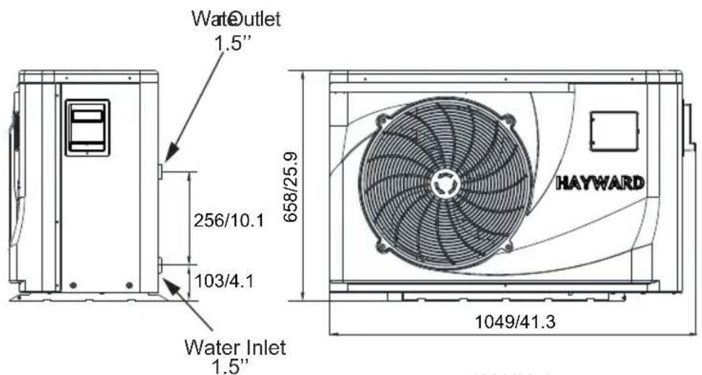
| Unit Net Dimensions(L/W/H) | mm/ inch | 1049×455×65841.3×17.9×25.9 | 956×360×60037.6×14.2×23.6 | 1115×450×86843.9×17.7×34.2 |
| Unit Shipping Dimensions(L/W/H) | mm/ inch | 1130×470×68044.5×18.5×26.8 | 1210×510×88047.6×20.1×34.6 | 1210×510×88047.6×20.1×34.6 |
| Net Weight | kg | See nameplate | ||
| Shipping Weight | kg | See package label | ||
Chauffage: Température Ambiante (BS/BM): 26.7°C (80°F) / 24.3°C (75.8°F); Temérature de l'eau (entrer/sortie): 26.7°C (80°F) / 28°C (92°F).
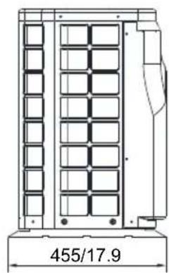
2.2 The dimensions for Swimming Pool Heat Pump Unit
HP50CL
Unit:mm/inch
natural_image
Technical line drawing of a vertical structural frame with internal grid pattern, labeled 455/17.9 (no text or symbols beyond label)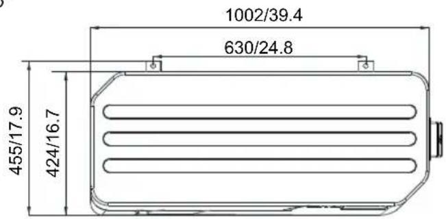
2.2 The dimensions for Swimming Pool Heat Pump Unit
HP65CL
Unit:mm/inch
natural_image
Technical line drawing of a vertical panel structure with dimension标注 (no text or symbols on the diagram itself)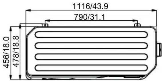
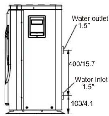
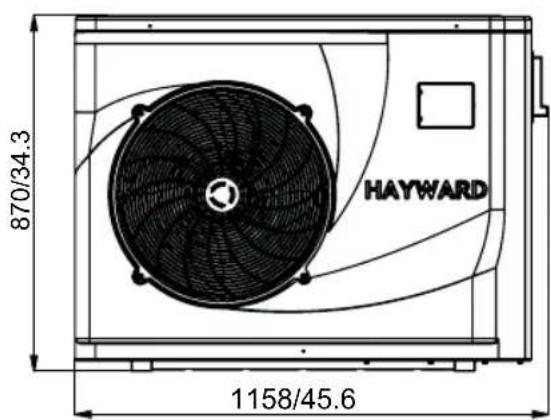
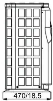
2.2 The dimensions for Swimming Pool Heat Pump Unit
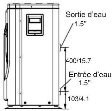
HP80CL
Unit:mm/inch
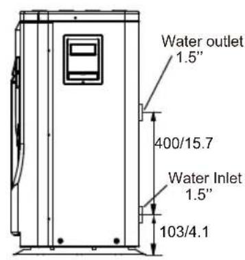
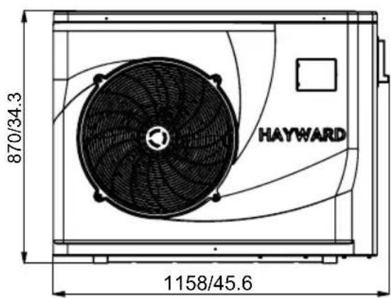
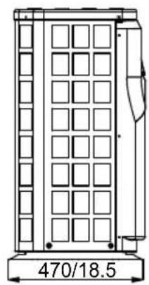
natural_image
Technical line drawing of a vertical panel structure with dimension标注 (no text or symbols on the diagram itself)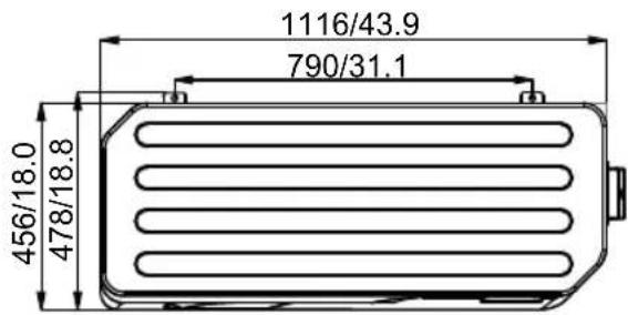
3.INSTALLATION AND CONNECTION
3.1 Installation illustration
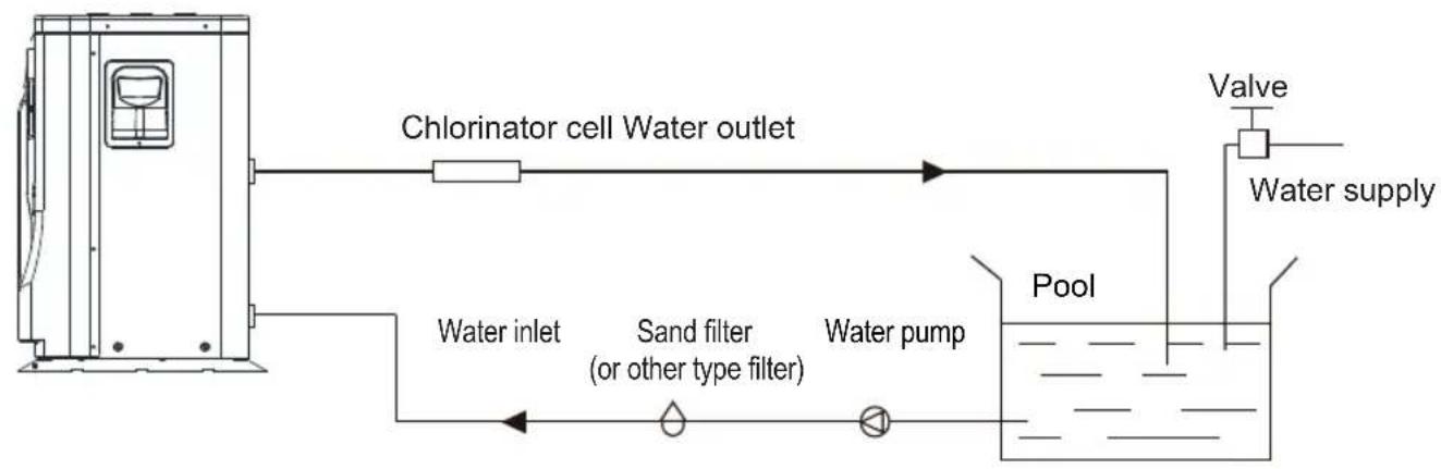
flowchart
graph LR
    A["Chlorinator cell Water outlet"] --> B["Pool"]
    B --> C["Water pump"]
    C --> D["Water inlet"]
    D --> E["Sand filter (or other type filter)"]
    E --> F["Valve"]
    F --> G["Water supply"]
Installation items:
The factory only provides the main unit and the water unit; the other items in the illustration are necessary spare parts for the water system, that provided by users or the installer.
Attention:
Please follow these steps when using for the first time
- Open valve and charge water.
- Make sure that the pump and the water-in pipe have been filled with water.
- Close the valve and start the unit.
ATTN: It is necessary that the water-in pipe is higher than the pool surface.
The schematic diagram is for reference only. Please check the water inlet/outlet label on the heat pump while plumbing installation.
3.INSTALLATION AND CONNECTION
3.2 Swimming Pool Heat Pumps Location
The unit will perform well in any outdoor location provided that the following three factors are presented:
- Fresh Air - 2. Electricity - 3. Pool filter piping
The unit may be installed virtually anywhere outdoors. For indoor pools please consult the supplier. Unlike a gas heater, it has no draft or pilot light problem in a windy area.
DO NOT place the unit in an enclosed area with a limited air volume, where the units discharge air will be re-circulated.
DO NOT place the unit to shrubs which can block air inlet. These locations deny the unit of a continuous source of fresh air which reduces it efficiency and may prevent adequate heat delivery.
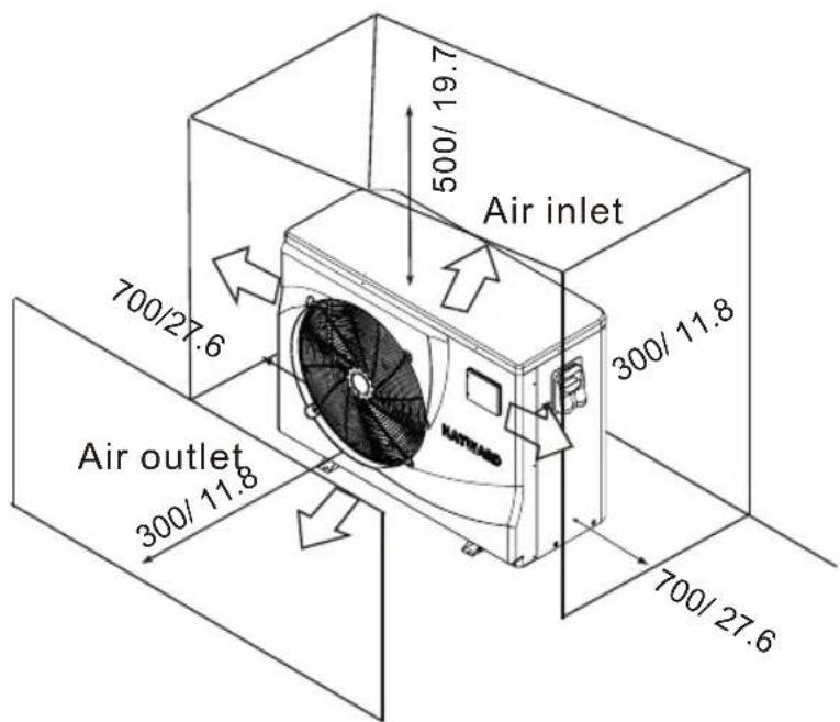
Unit:mm/inch
3.3 How Close To Your Pool?
Normally, the pool heat pump is installed within 7.5 metres of the pool. The longer the distance from the pool, the greater the heat loss from the piping. For the most part ,the piping is buried. Therefore, the heat loss is minimal for runs of up to15 meters(15 meters to and from the pump = 30 meters total), unless the ground is wet or the water table is high. A very rough estimate of heat loss per 30 meters is 0.6 kW-hour, (2000BTU) for every 5 ℃ difference in temperature between the pool water and the ground surrounding the pipe, which translates to about 3% to 5% increase in run time.
3.4 Swimming Pool Heat Pumps Plumbing
The Swimming Pool Heat Pumps exclusive rated flow titanium heat exchanger requires no special plumbing arrangements except bypass(please set the flow rate according to the nameplate). The water pressure drop is less than 10kPa at max. Flow rate. Since there is no residual heat or flame Temperatures, The unit does not need copper heat sink piping. PVC pipe can be run straight into the unit.
Location: Connect the unit in the pool pump discharge (return) line downstream of all filter and pool pumps, and upstream of any chlorinators, ozonators or chemical pumps.
Standard model have slip glue fittings which accept 32mm or 50 mm PVC pipe for connection to the pool or spa filtration piping. By using a 50 NB to 40NB you can plumb 40NB
Give serious consideration to adding a quick coupler fitting at the unit inlet and outlet to allow easy draining of unit for winterizing and to provide easier access should servicing be required.
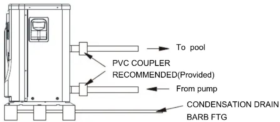
Condensation: Since the Heat pump cools down the air about 4 -5°C, water may condense on the fins of the horseshoe shaped evaporator. If the relative humidity is very high, this could be as much as several litres an hour. The water will run down the fins into the basepan and drain out through the barbed plastic condensation drain fitting on the side of the basepan. This fitting is designed to accept 20mm clear vinyl tubing which can be pushed on by hand and run to a suitable drain. It is easy to mistake the condensation for a water leak inside the unit.
NB: A quick way to verify that the water is condensation is to shut off the unit and keep the pool pump running. If the water stops running out of the basepan, it is condensation. AN EVEN QUICKER WAY IS to TEST THE DRAIN WATER FOR CHLORINE - if the is no chlorine present, then it's condensation.
3.5 Swimming Pool Heat Pumps Electrical Wiring
NOTE: Although the unit heat exchanger is electrically isolated from the rest of the unit, it simply prevents the flow of electricity to or from the pool water. Grounding the unit is still required to protect you against short circuits inside the unit. Bonding is also required.
The unit has a separate molded-in junction box with a standard electrical conduit nipple already in place. Just remove the screws and the front panel, feed your supply lines in through the conduit nipple and wire-nut the electric supply wires to the three connections already in the junction box (four connections if three phase). To complete electrical hookup, connect Heat Pump by electrical conduit, UF cable or other suitable means as specified (as permitted by local electrical authorities) to a dedicated AC power supply branch circuit equipped with the proper circuit breaker, disconnect or time delay fuse protection.
Disconnect - A disconnect means (circuit breaker, fused or un-fused switch) should be located within sight of and readily accessible from the unit. This is common practice on commercial and residential air conditioners and heat pumps. It prevents remotely-energizing unattended equipment and permits turning off power at the unit while the unit is being serviced.
3.6 Initial startup of the Unit
NOTE- In order for the unit to heat the pool or spa, the filter pump must be running to circulate water through the heat exchanger.
Start up Procedure - After installation is completed, you should follow these steps:
- Turn on your filter pump. Check for water leaks and verify flow to and from the pool.
- Turn on the electrical power supply to the unit, then press the key ON/OFF of wire controller, It should start in several seconds.
- After running a few minutes make sure the air leaving the top(side) of the unit is cooler(Between 5-10 ^ )
- With the unit operating turn the filter pump off. The unit should also turn off automatically,
- Allow the unit and pool pump to run 24 hours per day until desired pool water temperature is reached. When the water-in temperature reach setting, The unit just shuts off. The unit will now automatically restart (as long as your pool pump is running) when the pool temperature drops more than 2^ C below set temperature.
Time Delay- The unit is equipped with a 3 minute built-in solid state restart delay included to protect control circuit components and to eliminate restart cycling and contactor chatter. This time delay will automatically restart the unit approximately 3 minutes after each control circuit interruption. Even a brief power interruption will activate the solid state 3 minute restart delay and prevent the unit from starting until the 5 minute countdown is completed. Power interruptions during the delay period will have no effect on the 3 minute countdown.
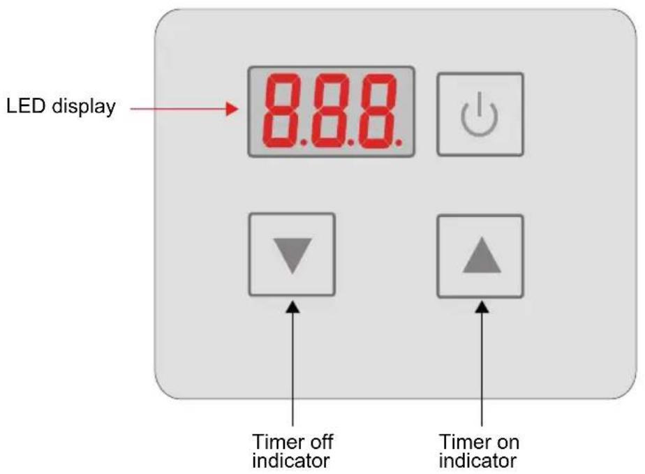
4.1. Function of wire controller

| Key Key name Key function | ||
| ON/OFF | Press this key to turn on/off the unit | |
| Up | Press this key to select the upward option or increase the parameter value. | |
| Down | Press this key to select the downward option or decrease the parameter value. | |
4.2. Usage of wire controller
4.2.1 Turn ON/OFF the unit
When the unit is off, press the key "0.5s to turned on the unit; When the unit is on, press the key "0.5s to show down the unit.
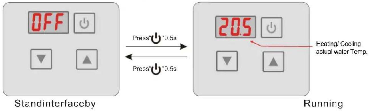
flowchart
graph LR
    A["Stand interface by"] -->|Press "0.5s" to Press "0.5s"| B["Running"]
    B --> C["Heating/ Cooling actual water Temp."]
4.2.2 Setting temperature
In the running interface, press“ ▲” or“▼” then the current mode target-temperature flashes, then press“ ▲” to increase the temp.value, or press“▼” to decrease it. Press“ ⏻” will not save setting parameter but back to the main interface; Attention: If there is no operation for 5s, system would remember parameter setting and back to the main interface. In the main interface, press“ ▲” for 2s you can see the outlet temp. The parameter is then flashed and the display is back to the main interface after 10s.
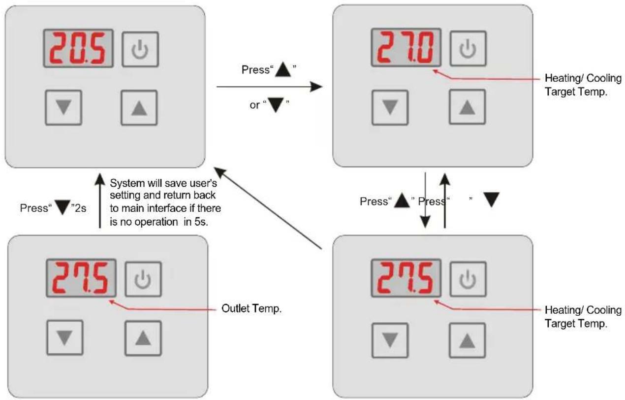
flowchart
graph TD
    A["20.5°C System"] -->|Press" ▲" or "▼" | B["27.0°C System"]
    B -->|Press" ▲" Press" ▼| C["27.5°C System"]
    C -->|Press" ▼" 2s System will save user's setting and return back to main interface if there is no operation in 5s.| D["Outlet Temp."]
4. USAGE
4.2.3 Mode switch
In the main interface, press “▲” and “▼” for 0.5s can set the mode, press “▲” or “▼” to change the current mode, you can switch different modes of colling, heating and auto mode. If there is no operation for 5s system will save the current mode and back to the main interface, press “↓” can not save setting. (The modes switching is useless of the unit you buy is singel-cold/single-heat unit.)
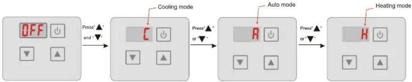
flowchart
graph LR
    A["OFF"] -->|Press'▲' and "▼'| B["C"]
    B -->|Press'▲' or "▼'| C["A"]
    C -->|Press'▲' or "▼'| D["H"]
    D --> E["Heating mode"]
4.2.4 Setting/ Displaying Temperatures
When unit is operating, press either “▲” or “▼” and the current temperature set point flashes. Then press either “▲” or “▼” to increase or decrease the temperature set point. Pressing will cancel the change and return operation to the original temperature display mode. To save the new temperature set point, do not press a key for 5s and the displayed value will be saved and operation will return to temperature display mode. To view the outlet temperature while in the temperature display mode press and hold “▲” for 2s. The outlet temperature is temporarily displayed, and then the display is returned to temperature display mode.
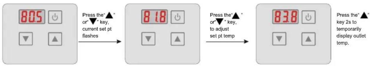
flowchart
graph LR
    A["805"] -->|Press the"▲" or▼"key, current set pt flashes| B["818"]
    B -->|Press the"▲" or▼"key, to adjust set pt temp| C["838"]
    C -->|Press the"▲" key 2s to temporarily display outlet temp.| D["End"]
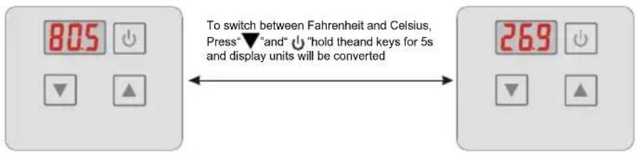
Fahrenheit and Celsius Setting:
4.2.5 Keyboard lock
To avoid mis-operations, please lock the controller after parameter setting.
At the main interface, pressing “ ⏻ ” for 5 seconds, when hearing one sound, the keyboard is locked. When the keyboard is locked, pressing “ ⏻ ” for 5 seconds, when hearing one sound, the keyboard lock is open.
NOTES: When the unit is in alarming state, the key lock can be removed automatically.
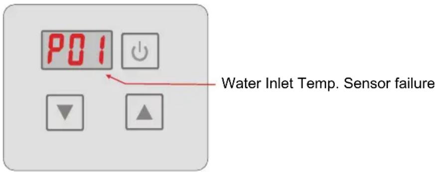
4.2.6 Malfunction display
There will be malfunction code showing on the controller screen when relative malfunction occurs.
If there are more than one malfunctions occurs at the same time, you can check the current error codes list by pressing “▲” or “▼” key.
You can refer to the malfunction table to find out the failure cause and solution. For example:
4.3. Parameter table
| Meaning Default Remarks | ||
| Set-point of auto mode target temp. | 27°Ajustable | |
- Remark:
The wire controller can display the temperature unit as "F" or "C" according to the unit Model you bought.
4.4 Malfunction Table
The common failure cause and solution.
| Malfunction | Display | Cause | Solution |
| Water inlet temp. Sensor failure | P01 | The water inlet temp. Sensor is open or short circuit | Check or change the water inlet temp. Sensor |
| Water outlet temp. Sensor failure | P02 | The water outlet temp. sensor is open or short circuit | Check or change the water outlet temp. Sensor |
| Ambient temp. Sensor failure | P04 | The ambient temp. sensor is open or short circuit | Check or change the ambient temp. Sensor |
| Pipe temp. Sensor failure | P05 | The pipe temp. sensor is open or short circuit | Check or change the pipe temp. Sensor |
| Evaporator temp.Sensor failure | P07 | The evaporator temp. Sensor is open or short circuit | Check or change the evaporator temp. Sensor |
| High pressure protect | E01 | The exhaust pressure is high, high pressure switch action | Check high pressure switch and cooling return circuit |
| Low pressure protect | E02 | The suction pressure is low, Low pressure switch action | Check low pressure switch and cooling return circuit |
| Flow switch failure | E03 | No water or litter water in water system | Check the flow volume ,water pump is failure or not |
| Temp. is too much different between water-inlet and outlet | E06 | Water flow volume not enough, Water system pressure difference is small | Check the flow volume,water system is jammed or not |
| Antifreezing under cooling mode | E07 | Water flow volume not enough | Check the flow volume,water system is jammed or not |
| The primary anti-freezing protection start. | E19 | Ambient temperature is too low | |
| The second anti-freezing protection start | E29 | Ambient temperature is too low | |
| Communication failure | E08 | Communication failure between remote wire controller and main board | Check the wire connection between remote wire controller and main board |
5.1 Maintenance and inspection
- Check the water supply device and the release often. You should avoid the condition of no water or air entering into system, as this will influence unit's performance and reliability. You should clear the pool/spa filter regularly to avoid damage to the unit as a result of the dirty of clogged filter.
- The area around the unit should be dry, clean and well ventilated. Clean the side heating exchanger regularly to maintain good heat exchange as conserve energy.
- The operation pressure of the refrigerant system should only be serviced by a certified technician.
- Check the power supply and cable connection often. Should the unit begin to operate abnormally, switch it off and contact the qualified technician.
- Discharge all water in the water pump and water system, so that freezing of the water in the pump or water system does not occur. You should discharge the water at the bottom of water pump if the unit will not be used for an extended period of time. You should check the unit thoroughly and fill the system with water fully before using it for the first time after a prolonged period of no usage.
5.2 Winterization
The following winterization steps are important to prevent freeze damage.
- Set the heat pump in "OFF" mode.
- Remove power power to the heat pump.
- Drain the appliance of all its water:
- Disconnect the water inlet and outlet connections.
- Slightly tilt the unit so that the inlet and outlet pipes point towards the ground and allow water to drain completely.
- Remove any remaining water using a "Shop Vac" style vacuum cleaner. Connect the exhaust side of the vacuum cleaner to the upper port (outlet) of the heat pump to push any remaining water that may be left inside.
- Do not reconnect the plumbing to the heat pump.
- Plug the water inlet and outlet to prevent intrusion of small animals or debris during winter.
- Do not wrap the heat pump with canvas or tarpaulin as some canvas can cause discoloration of the equipment. This can also trap moisture which can promote rusting of metal components.

A HEAT PUMP DAMAGED BY FREEZING IS NOT COVERED UNDER THE MANUFACTURER'S WARRANTY.
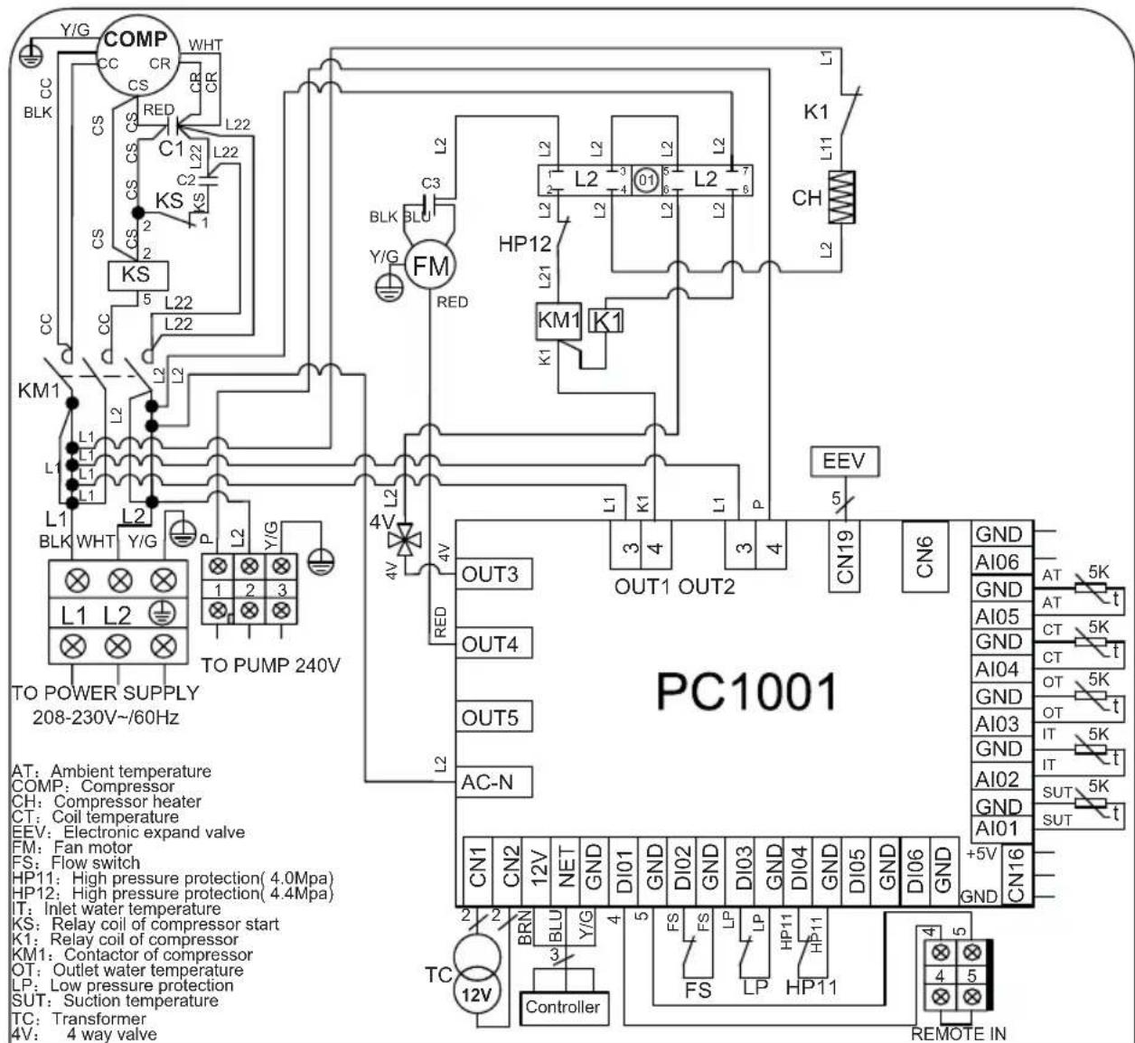
6.1 Connection of PCB illustration
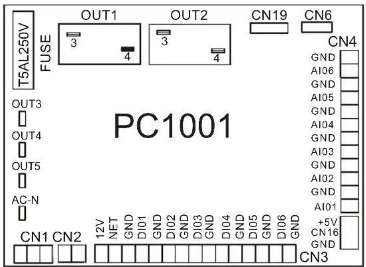
Connections explanation:
| No. | Symbol | Meaning |
| 1 | OUT1 | Compressor of system1 (220-230VAC) |
| 2 | OUT2 | Water pump (220-230VAC) |
| 3 | OUT3 | 4way valve (220-230VAC) |
| 4 | OUT4 | High speed of fan motor (220-230VAC) |
| 5 | OUT5 | Low speed of fan motor (220-230VAC) |
| 6 | AC-N | Neutral wire |
| 7 | NET GND 12V | Wire controller |
| 8 | DI01 GND | On/Off Switch (input) (no use) |
| 9 | DI02 GND | Flow switch (input) (normal close) |
| 10 | DI03 GND | Low pressure protect |
| 11 | DI04 GND | High pressure protect |
| 12 | DI05 GND | No use |
| 13 | DI06 GND | No use |
| 14 | AI01 GND | Suction temp.(input) |
| 15 | AI02 GND | Water in temp.(input) |
| 16 | AI03 GND | Water out temp.(input) |
| 17 | AI04 GND | Coil Temp. ( input) |
| 18 | AI05 GND | Ambient temp.(input) |
| 19 | AI06 GND | Ajustable fan speed/Exhaust temperature |
| 20 | CN1 | Primary transformer |
| 21 | CN2 | Secondary transformer |
| 22 | CN6 | No use |
| 23 | CN19 | Electronic expansion valve |
| 24 | 5V CN16 GND | Flow meter |
6.2 Wiring Diagram
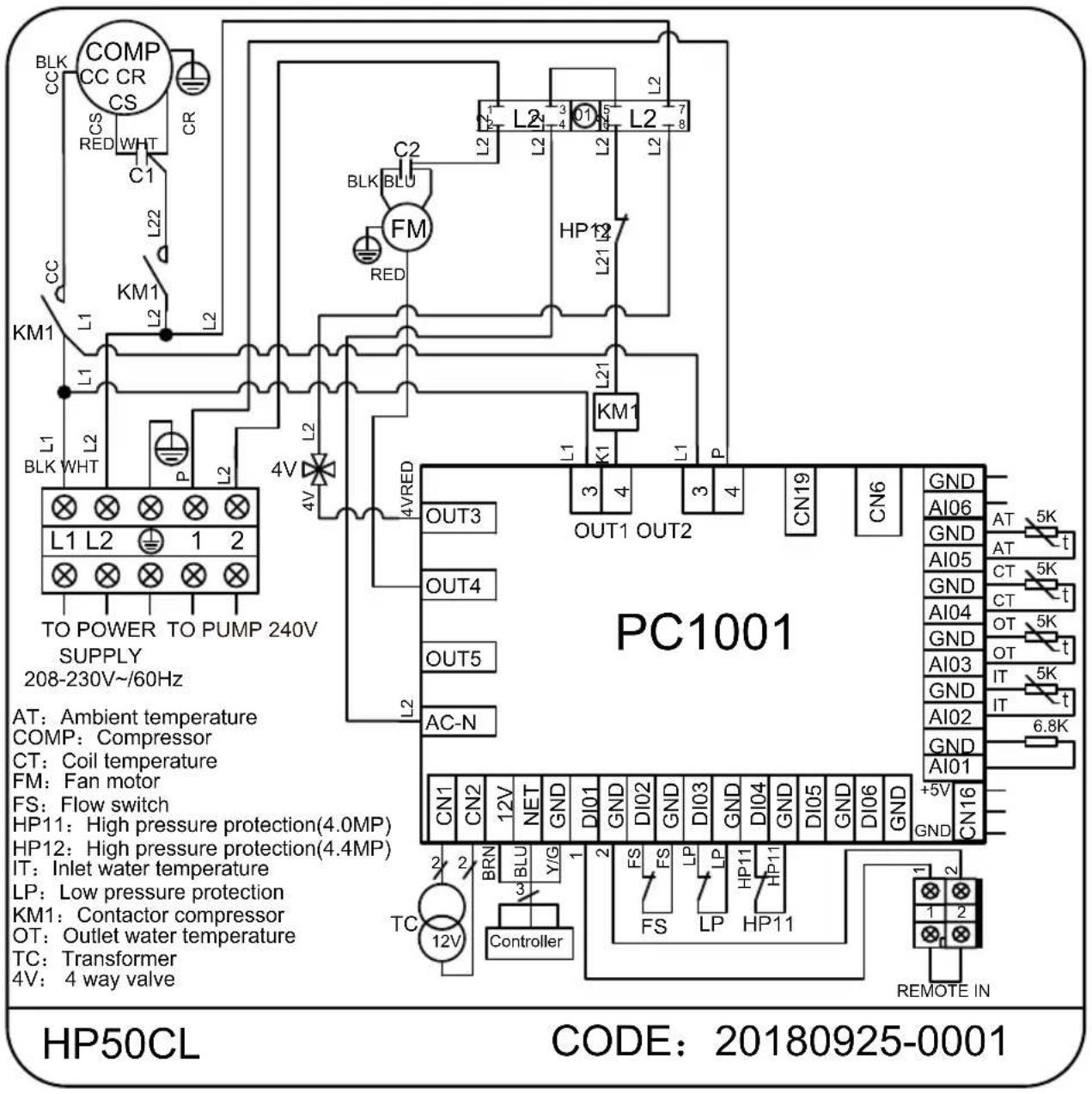
6.2 Wiring Diagram
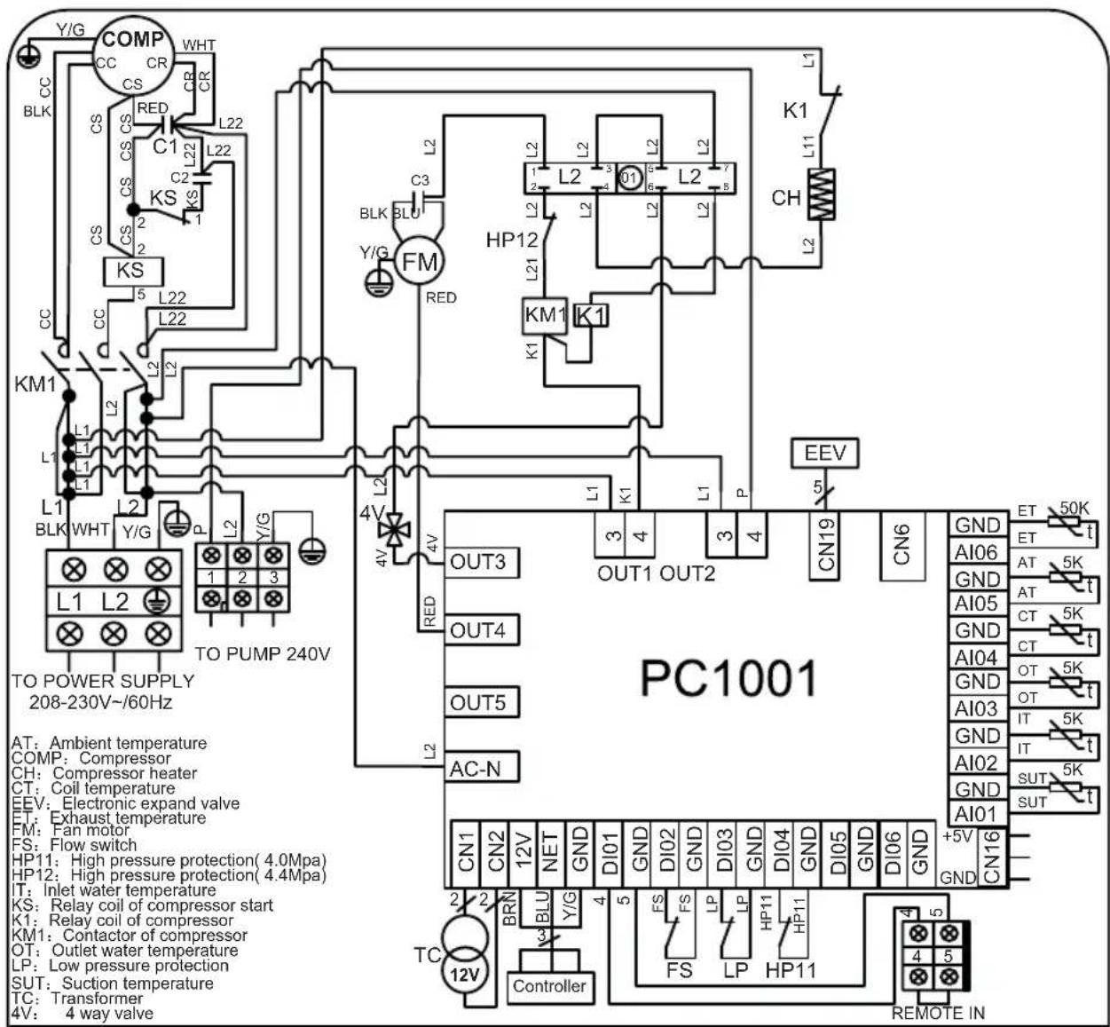
HP65CL
CODE: 20201210-0008
6.2 Wiring Diagram
HP80CL
CODE: 20201210-0009
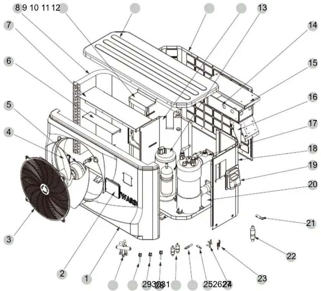
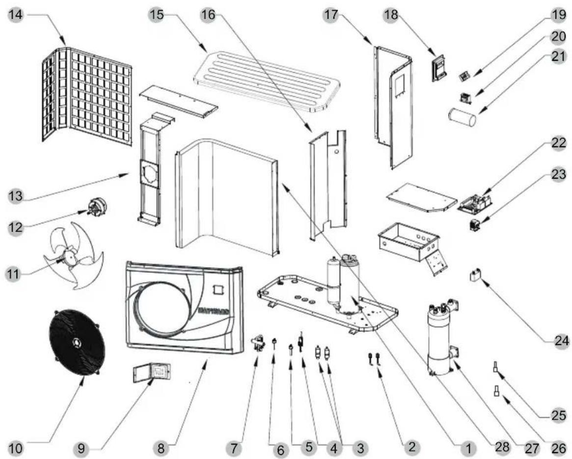
6.3 Exploded View(HP50CL)
(1) Complete machine structure explosion diagram
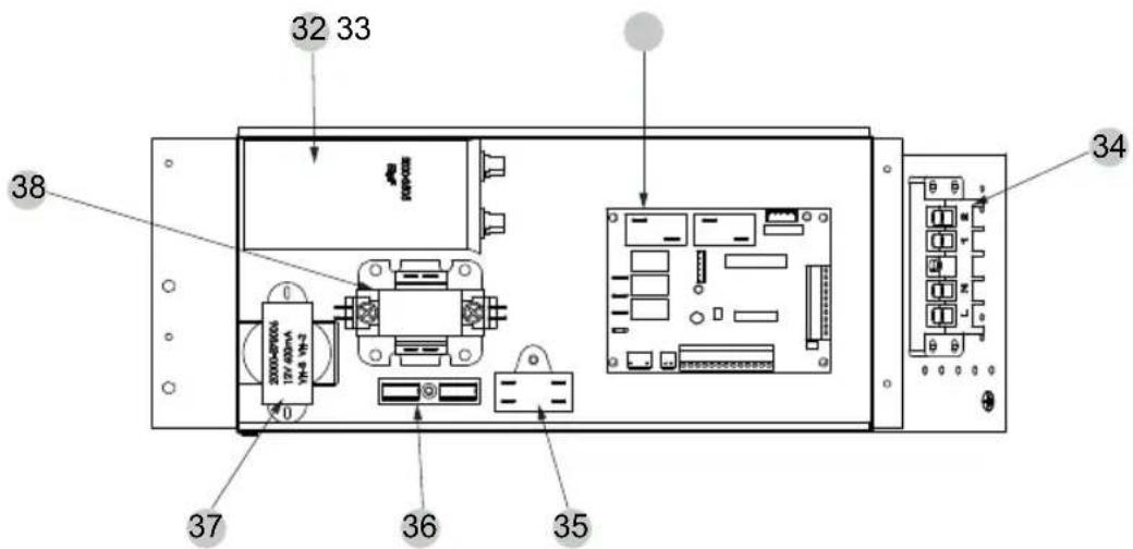
(2) Electrical control structure explosion diagram
(3) Spare Parts List
| SN | HPX Code Description | Specifications | Qty | |
| 1 | HPX80900197 | Front frame | ABS | 1 |
| 2 | HPX72200268 | LED207 Wire controller | 82300029+82400226 | 1 |
| 3 | HPX20000-220188 | Plastic fan net | 507 ABS+30%GF | 1 |
| 4 | HPX3500-2701 | Fan blade | 440 × 152 AS+20%GF | 1 |
| 5 | HPX20000-330124 | Motor | YDK45-6(YY060-1206P01-004) UL | 1 |
| 6 | HPX32008-210069 | Before the fixed plate | Galvanized sheet | 1 |
| 7 | HPX32012-210737 | Support plate | Galvanized sheet | 1 |
| 8 | HPX32012-120165 | Finned heat exchanger | 746.5×284×600× 7 ×2 2.0 | 1 |
| 9 | HPX32012-210742 | Motor bracket | Galvanized sheet | 1 |
| 10 | HPX32012-220009 | Top | ABS | 1 |
| 11 | HPX80700707 | On the left side of the plate | Galvanized sheet | 1 |
| 12 | HPX80700713 | Partition | Galvanized sheet | 1 |
| 13 | HPX20000-110041 | Compressor | PA270X3CS-3MUU | 1 |
| 14 | HPX32012-210739 | Electrical box | Galvanized sheet | 1 |
| 15 | HPX32012-210740 | Cover plate | Galvanized sheet | 1 |
| 16 | HPX32012-210220 | Fire damper | Galvanized sheet | 1 |
| 17 | HPX32012-120036 | Titanium tube heat exchanger | 12.7 × 9m 160 | 1 |
| 18 | HPX80700706 | Right side of the plate | Galvanized sheet | 1 |
| 19 | HPX32009-220029 | Junction box body | ABS | 1 |
| 20 | HPX80700708 | Chassis | Galvanized sheet | 1 |
| 21 | HPX2002-1443 | Get straight through | 19- 12.9 × 1.0 T2M | 1 |
| 22 | HPX2001-1499 | Check valve | PKV-6X1 | 1 |
| 23 | HPX20000-140150 | Needle valve | 40mm 1/2" | 2 |
| 24 | HPX2000-1460 | Tee | 6.5-2 × 6.5(T) × 0.75 T2M | 2 |
| 25 | HPX20000-140058 | Get straight through | 9.52- 3. × 0.75 T2M | 1 |
| 26 | HPX20000-140067 | Double capillary joint | 2× 3.4- 9.52 | 1 |
| 27 | HPX2004-1444 | Filter | 9.7- 9.7 (Φ28) T2Y2 | 2 |
| 28 | HPX2000-3603 | Pressure switch | 0.30MPa/0.15MPa ±0.05 NO | 1 |
| 29 | HPX2001-3605 | Pressure switch | 3.2MPa/4.4MPa ±0.15 NC | 1 |
| 30 | HPX20000-360059 | Pressure switch | 3.2MPa/4.0MPa ±0.15 NC | 1 |
| 31 | HPX2001-1418 | Four-way valve | SHF-7H-34U-P/C02C00S | 1 |
| 32 | HPX2000-3505 | Compressor capacitor | CBB65-50μF/450V P2 Blv | 1 |
| 33 | HPX95005-310145 | PC1001 | 20000-430001+35005-310145 | 1 |
| 34 | HPX20000-390231 | Five position connector | UTD-32/5P(L1、L2、PE、1、2) | 1 |
| 35 | HPX2000-3501 | Fan capacitor | CBB61-3μF/500V(450V)P2 | 1 |
| 36 | HPX2000-3909 | Two position connector | RS9211(450V~ 4mm2) | 1 |
| 37 | HPX20000-370006 | Power transformer | 41X26.5F+red(VH-3)、yellow(VH-2) | 1 |
| 38 | HPX20000-360103 | Single-phase ac contactor | HCC-2XU04AA415 | 1 |
6.3 Exploded View(HP65CL)
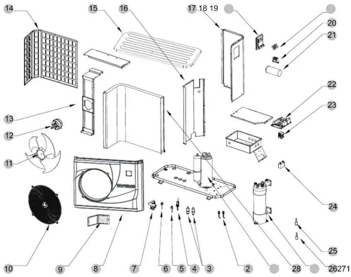
(3) Spare Parts List
| SN | HPX Code Description | Specifications | Qty | |
| 1 | HPX20000-110192 | Compressor | C-SBP105H16A | 1 |
| 2 | HPX20000-140153 | Needle valve | 90mm 1/2" T0306-10 | 2 |
| 3 | HPX2004-1444 | Filter | Φ9.7-Φ4.2(Φ28) T2Y2 | 2 |
| 4 | HPX20000-360005 | Water Flow switch | PSL-1 3/4 | 1 |
| 5 | HPX2000-3603 | Pressure switch | 0.30MPa/0.15MPa ±0.05 | 1 |
| 6 | HPX20000-360059 | Pressure switch | 3.2MPa/4.0MPa ±0.15 | 1 |
| 7 | HPX2004-1437 | 4-way vlave | SHF-9H-35U-P/C03C01S | 1 |
| 8 | HPX80901028 | Front panel | ABS | 1 |
| 9 | HPX72200268 | LED207 Wire controller | 82300029+82400226 | 1 |
| 10 | HPX20000-220169 | Plastic fan net | Φ500 | 1 |
| 11 | HPX20000-270004 | Axial flow fan | Z500-145 | 1 |
| 12 | HPX20000-330143 | Axial flow fan | YDK90-6(YY070-1206P01-001) | 1 |
| 13 | HPX32009-210204 | Fan Motor bracket | Galvanized sheet | 1 |
| 14 | HPX80708920 | Back net | Galvanized sheet | 1 |
| 15 | HPX32009-210331 | Top cover | ABS | 1 |
| 16 | HPX32009-210220 | Middle partition | Galvanized sheet | 1 |
| 17 | HPX80711034 | Right panel | Galvanized sheet | 1 |
| 18 | HPX20000-220284 | The junction box body | ABS | 1 |
| 19 | HPX2000-3909 | 3-position terminal block | RS9211(450V~ 4mm2) | 1 |
| 20 | HPX20000-370006 | Transformer | 41X26.5F+(VH-3)、(VH-2) | 1 |
| 21 | HPX2000-3524 | Compressor capacitor | BB65A-98μF/300VAC | 1 |
| 22 | HPX95005-310145 | PC1001 Controller | 82300022+35005-310145 | 1 |
| 23 | HPX20000-360125 | Ac contactor | XTCG032C00AO | 1 |
| 24 | HPX2000-3509 | Fan capacitor | CBB61-5uF/500V(450V)P2 | 1 |
| 25 | HPX2000-3242 | Sensor | 150-502-98674(5K) 800mm | 1 |
| 26 | HPX2000-3223 | Sensor | 714×353×800×Φ7×2 2.0 | 1 |
| 27 | HPX32009-120025 | Titanium Tube Heat Exchanger | Φ12.7×12m Φ160 | 1 |
| 28 | HPX32009-120021 | Fin Heat Exchanger | 150-503-96115(50K) 600mm | 1 |
6.3 Exploded View(HP80CL)
(3) Spare Parts List
| SN | HPX Code Description | Specifications | Qty | |
| 1 | HPX20000-110038 | Compressor | C-SBP120H16A | 1 |
| 2 | HPX20000-140153 | Needle valve | 90mm 1/2" T0306-10 | 2 |
| 3 | HPX2004-1445 | Filter | Φ9.7-Φ4.2(Φ28) T2Y2 | 2 |
| 4 | HPX20000-360005 | Water Flow switch | PSL-1 3/4 | 1 |
| 5 | HPX2000-3603 | Pressure switch | 0.30MPa/0.15MPa ±0.05 | 1 |
| 6 | HPX20000-360059 | Pressure switch | 3.2MPa/4.0MPa ±0.15 | 1 |
| 7 | HPX2001-1491 | 4-way vlave | SHF-20A-46/V6-412080-1XX | 1 |
| 8 | HPX80901028 | Front panel | ABS | 1 |
| 9 | HPX72200268 | LED207 Wire controller | 82300029+82400226 | 1 |
| 10 | HPX20000-220169 | Plastic fan net | Φ500 | 1 |
| 11 | HPX20000-270004 | Axial flow fan | Z500-145 | 1 |
| 12 | HPX20000-330143 | Axial flow fan | YDK90-6(YY070-1206P01-001)UL | 1 |
| 13 | HPX32009-210204 | Fan Motor bracket | Galvanized sheet | 1 |
| 14 | HPX80708920 | Back net | Galvanized sheet | 1 |
| 15 | HPX32009-210331 | Top cover | ABS | 1 |
| 16 | HPX32009-210220 | Middle partition | Galvanized sheet | 1 |
| 17 | HPX80711034 | Right panel | Galvanized sheet | 1 |
| 18 | HPX20000-220284 | The junction box body | ABS | 1 |
| 19 | HPX2000-3909 | 3-position terminal block | UTD-63A/3P(L N PE) | 1 |
| 20 | HPX20000-370006 | Transformer | 41X26.5F+(VH-3)、(VH-2) | 1 |
| 21 | HPX2000-3524 | Compressor capacitor | BB65A-98μF/300VAC | 1 |
| 22 | HPX95005-310145 | PC1001 Controller | 82300022+35005-310145 | 1 |
| 23 | HPX20000-360125 | Ac contactor | XTCG032C00AO | 1 |
| 24 | HPX2000-3509 | Fan capacitor | CBB61-5uF/500V( 450V)P2 | 1 |
| 25 | HPX2000-3242 | Sensor | 150-502-98674(5K) 800mm | 1 |
| 26 | HPX2000-3223 | Sensor | 150-503-96115(50K) 600mm | 1 |
| 27 | HPX32010-120012 | Titanium Tube Heat Exchanger | Φ12.7×14m Φ160SSSS | 1 |
| 28 | HPX32009-120021 | Fin Heat Exchanger | 714×353×800×Φ7×2 2.0 | 1 |
6.4 Caution & Warning
- The unit can only be repaired by the qualified personnel of an installer center or an authorized dealer.
- This appliance is not intended for use by persons (including children) with reduced physical sensory or mental capabilities, or lack of experience and knowledge, unless they have been given supervision or instruction concerning use of the appliance by a person responsible for their safety.
Children should be supervised to ensure that they do not play with the appliance.
-
Please make sure that the unit and power connection have good earthing, otherwise may cause electrical shock.
-
If the supply cord is damaged, it must be replaced by the manufacturer or our service agent or similarly qualified person in order to avoid a hazard.
-
Directive 2002/96/EC (WEEE):
The symbol depicting a crossed-out waste bin that is underneath the appliance indicates that this product, at the end of its useful life, must be handled separately from domestic waste, must be taken to a recycling centre for electric and electronic devices or handed back to the dealer when purchasing an equivalent appliance.
-
Directive 2002/95/EC (RoHs): This product is compliant with directive 2002/95/EC (RoHs) concerning restrictions for the use of harmful substances in electric and electronic devices.
-
The unit CANNOT be installed near the flammable gas. Once there is any leakage of the gas, fire can be occur.
-
Make sure that there is circuit breaker for the unit, lack of circuit breaker can lead to electrical shock or fire.
-
The heat pump located inside the unit is equipped with an over-load protection system. It does not allow for the unit to start for at least 3 minutes from a previous stoppage.
-
Installation must be performed in accordance with the NEC/CEC by authorized person only.
(for North America market)
-
USE SUPPLY WIRES SUITABLE FOR 75°C.
-
Caution: Single wall heat exchanger, not suitable for potable water connection.
Cable specification
- Single phase unit
| Nameplate maximum current | Phase line Earth line MCB Creepage protector Signal line | ||||
| No more than 10A | 2 × 1,5 mm^2 | 1,5 mm^2 | 20 A | 30mA less than 0.1 sec | n × 0.5 mm^2 |
| 10~16 A | 2 × 2,5 mm^2 | 2,5 mm^2 | 32 A | 30mA less than 0.1 sec | |
| 16~25 A | 2 × 4 mm^2 | 4 mm^2 | 40 A | 30mA less than 0.1 sec | |
| 25~32 A | 2 × 6 mm^2 | 6 mm^2 | 40 A | 30mA less than 0.1 sec | |
| 32~40 A | 2 × 10 mm^2 | 10 mm^2 | 63 A | 30mA less than 0.1 sec | |
| 40 ~63 A | 2 × 16 mm^2 | 16 mm^2 | 80 A | 30mA less than 0.1 sec | |
| 63~75 A | 2 × 25 mm^2 | 25 mm^2 | 100 A | 30mA less than 0.1 sec | |
| 75~101 A | 2 × 25 mm^2 | 25 mm^2 | 125 A | 30mA less than 0.1 sec | |
| 101~123 A | 2 × 35 mm^2 | 35 mm^2 | 160 A | 30mA less than 0.1 sec | |
| 123~148 A | 2 × 50 mm^2 | 50 mm^2 | 225 A | 30mA less than 0.1 sec | |
| 148~186 A | 2 × 70 mm^2 | 70 mm^2 | 250 A | 30mA less than 0.1 sec | |
| 186~224 A | 2 × 95 mm^2 | 95 mm^2 | 280 A | 30mA less than 0.1 sec | |
- Three phase unit
| Nameplate maximum current | Phase line Earth line MCB Creepage protector Signal line | ||||
| No more than 10A | 3×1,5 mm2 | 1,5 mm2 | 20 A | 30mA less than 0.1 sec | n×0.5mm2 |
| 10~16 A | 3×2,5 mm2 | 2,5 mm2 | 32 A | 30mA less than 0.1 sec | |
| 16~25 A | 3×4 mm2 | 4 mm2 | 40 A | 30mA less than 0.1 sec | |
| 25~32 A | 3×6 mm2 | 6 mm2 | 40 A | 30mA less than 0.1 sec | |
| 32~40 A | 3×10 mm2 | 10 mm2 | 63 A | 30mA less than 0.1 sec | |
| 40 ~63 A | 3×16 mm2 | 16 mm2 | 80 A | 30mA less than 0.1 sec | |
| 63~75 A | 3×25 mm2 | 25 mm2 | 100 A | 30mA less than 0.1 sec | |
| 75~101 A | 3×25 mm2 | 25 mm2 | 125 A | 30mA less than 0.1 sec | |
| 101~123 A | 3×35 mm2 | 35 mm2 | 160 A | 30mA less than 0.1 sec | |
| 123~148 A | 3×50 mm2 | 50 mm2 | 225 A | 30mA less than 0.1 sec | |
| 148~186 A | 3×70 mm2 | 70 mm2 | 250 A | 30mA less than 0.1 sec | |
| 186~224 A | 3×95 mm2 | 95 mm2 | 280 A | 30mA less than 0.1 sec | |
When the unit will be installed at outdoor, please use the cable which can against UV.
6.4 Warranty
HAYWARD ^® HEAT PUMP POOL HEATERS LIMITED WARRANTY
The HAYWARD heat pump pool heater is warranted to be free of defects in materials and workmanship for a period of one (1) year for parts and (1) one year for labor.
Warranty is applicable to the original location and owner only and is not transferable. The compressor component has a two (2) year limited warranty with parts & labour warranted the first year and parts only warranted in year two.
The titanium tube component of the heat exchanger has a five (5) year parts only warranty.
HAYWARD will not void this warranty due to improper pool chemistry.
This warranty is valid only if the product is installed according to the HAYWARD specifications.
This warranty does not include refrigerant or other expendable materials, or services such as inspection, maintenance, or unnecessary service calls due to erroneous operational reports, external valve position, or electrical service. It also does not include the repair of damage due to negligence, accident, freezing, or other conditions beyond the normal intended use of the unit. This warranty is void if the product is repaired or altered in any way by any persons or agencies other than those authorized by HAYWARD, and is in lieu of all other warranties, expressed or implied, written or oral. There are no implied warranties of merchantability or fitness for a particular purpose that apply to this product. This warranty applies only within Canada.
At its option, HAYWARD will replace or repair any HAYWARD part that proves defective if such parts are returned to our factory, freight collect, within the warranty period. It is agreed that such replacement or repair is the exclusive remedy available from HAYWARD. Unless authorized by HAYWARD and performed by a factory authorized service center, HAYWARD is not liable for any labor involved in the removal of defective parts or the installation of replacement parts. HAYWARD is not liable for damages of any sort whatsoever, including incidental and consequential damages. Parts returned and services performed under terms of this warranty must be approved by HAYWARD. All parts returned under terms of this warranty will be repaired or replaced and returned transportation charges prepaid, by best and most economical means.
Hayward Pool Products Canada, Inc.
2880 Plymouth Dr., Oakville, ON L6H 5R4
www.haywardpool.ca / 888-238-7665
Retain this Warranty Certificate in a safe and convenient location for your records

natural_image
Abstract geometric logo with a white circle containing black squares and a central 'H' shape, no text or symbols present.HAYWARD®
THERMOPOMPE POUR PISCINE
natural_image
Exterior view of a black Hayward air conditioning unit with a circular fan and control panel (no visible text or symbols)1. Préface 1
2. Spécifications 2
natural_image
Technical line drawing of a vertical panel or enclosure with grid patterns, labeled 470/18.5 at the base (no text or symbols on the diagram itself)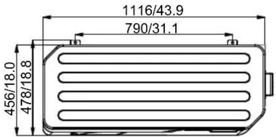
2.SPÉCIFICATIONS
2.2 Dimensions de la thermopompe de piscine
HP80CL
Unité: mm/inch
natural_image
Technical line drawing of a vertical panel structure with dimension标注 (no text or symbols on the diagram itself)
3.INSTALLATION ET RACCORDEMENT
4.1. Function of wire controller
Hayward Pool Products Canada, Inc.
T: 1-888-238-7665
www.haywardpool.ca
Code: 83900031
- HAYWARD®
- SWIMMING POOL HEAT PUMP UNIT
- Preface 1
- Specifications 2
- Installation and Connection 6
- Usage and Operation 10
- Maintenance and Inspection 15
- Appendix
- PREFACE
- Performance data of Swimming Pool Heat Pump Unit
- The dimensions for Swimming Pool Heat Pump Unit
- 3.INSTALLATION AND CONNECTION
- Installation illustration
- Installation items:
- Attention:
- Swimming Pool Heat Pumps Location
- How Close To Your Pool?
- Swimming Pool Heat Pumps Plumbing
- Swimming Pool Heat Pumps Electrical Wiring
- Initial startup of the Unit
- Function of wire controller
- USAGE
- Mode switch
- Setting/ Displaying Temperatures
- Keyboard lock
- Malfunction display
- Parameter table
- - Remark:
- Malfunction Table
- Maintenance and inspection
- Winterization
- Connection of PCB illustration
- Wiring Diagram
- Exploded View(HP50CL)
- Caution & Warning
- Cable specification
- Warranty
- HAYWARD ® HEAT PUMP POOL HEATERS LIMITED WARRANTY
- THERMOPOMPE POUR PISCINE
- Préface 1
- Spécifications 2
- 2.SPÉCIFICATIONS
- Dimensions de la thermopompe de piscine
- 3.INSTALLATION ET RACCORDEMENT
Brand : HAYWARD
Model : Classic Heat Pump
Category : Heating