LE600 - Basket Air King - Free user manual and instructions
Find the device manual for free LE600 Air King in PDF.
User questions about LE600 Air King
0 question about this device. Answer the ones you know or ask your own.
Ask a new question about this device
Download the instructions for your Basket in PDF format for free! Find your manual LE600 - Air King and take your electronic device back in hand. On this page are published all the documents necessary for the use of your device. LE600 by Air King.
USER MANUAL LE600 Air King
SAVE THESE INSTRUCTIONS
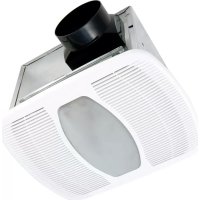
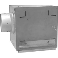
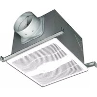
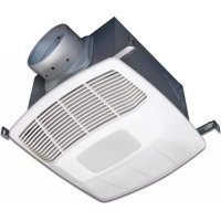
www.airkinglimited.com6727921 Rev. F 12-18 1 of 12 Power Unit Models: LE600A, LE600, L600
WARNING: TO REDUCE THE RISK OF FIRE,
ELECTRIC SHOCK AND INJURY TO PERSON, OBSERVE THE FOLLOWING: a) Use this unit only in the manner intended by the manufacturer.If you have questions, contact the manufacturer.b) Before servicing or cleaning the unit, switch power off at service panel and lock the service disconnecting means to prevent power from being switched on accidentally. When the service disconnecting means cannot be locked, securely fasten a prominent warning device, such as a tag, to the service panel.
WARNING: TO REDUCE THE RISK OF FIRE,
ELECTRIC SHOCK AND INJURY TO PERSON, OBSERVE THE FOLLOWING: a) Installation work and electrical wiring must be done by qualified person(s) in accordance with all applicable codes and standards, including fire-related construction.b) Sufficient air is needed for proper combustion and exhausting of gases through the flue (chimney) of fuel burning equipment to prevent back drafting. Follow the heating equipment manufacturer’s guideline and safety standards such as those published by the National Fire Protection Association (NFPA) and the American Society for Heating, Refrigeration, and Air Conditioning Engineers (ASHRAE), and the local code authorities.c) When cutting or drilling into wall or ceiling, do not damage electrical wiring and other hidden utilities. CAUTION: FOR GENERAL VENTILATING USE ONLY. DO NOT USE TO EXHAUST HAZARDOUS OR EXPLOSIVE MATERIALS AND VAPORS. CAUTION: TO REDUCE THE RISK OF FIRE AND TO PROPERLY EXHAUST AIR, BE SURE TO DUCT AIR OUTSIDE - DO NOT VENT EXHAUST AIR INTO SPACES WITHIN WALLS OR CEILINGS OR INTO ATTICS, CRAWL SPACES, OR GARAGES.d) Ducted fans must always be vented to the outdoors.e) This unit must be grounded.f) To avoid motor bearing damage and noisy and/or unbalanced impellers, keep drywall spray, construction dust, etc. off power unit.g) Read all instructions before installing or using range hood.
SHOCK, DO NOT USE THIS FAN WITH ANY SOLID-STATE SPEED CONTROL DEVICE.
GREASE FIRE: a) Never leave surface units unattended at high settings. Boil overs cause smoking and greasy spillovers that may ignite. Heat oils slowly on low or medium settings. b) Always turn hood ON when cooking at high heat or when flambéing food (ie. Crepes Suzette, Cherries Jubilee, Peppercorn Beef Flambé). c) Clean ventilating fans frequently. Grease should not be allowed to accumulate on fan filter. d) Use proper pan size. Always use cookware appropriate for the size of the surface element.
WARNING: TO REDUCE THE RISK OF INJURY TO PERSONS
IN THE EVENT OF A RANGE TOP GREASE FIRE, OBSERVE THE FOLLOWING: a) SMOTHER FLAMES with a close-fitting lid, cookie sheet, or metal tray, then turn off burner. BE CAREFUL TO PREVENT BURNS. If the flames do not go out immediately, EVACUATE AND CALL THE FIRE DEPARTMENT. b) NEVER PICK UP A FLAMING PAN - You may be burned. c) DO NOT USE WATER, including wet dishcloths or towels - a violent steam explosion will result. d) Use an extinguisher ONLY if: I. You know you have a Class ABC extinguisher, and you already know how to operate it. II. The fire is small and contained in the area where it started. III. The fire department is being called. IV. You can fight the fire with your back to an exit.
WARNING: TO REDUCE THE RISK OF FIRE, USE ONLY
WARNING: THE DUCTING FROM THIS FAN TO THE OUTSIDE OF
THE BUILDING HAS A STRONG EFFECT ON THE AIR FLOW, NOISE AND ENERGY USE OF THE FAN. USE THE SHORTEST, STRAIGHTEST DUCT ROUTING POSSIBLE FOR BEST PERFORMANCE, AND AVOID INSTALLING THE FAN WITH SMALLER DUCTS THAN RECOMMENDED. INSULATION AROUND THE DUCTS CAN REDUCE ENERGY LOSS AND INHIBIT MOLD GROWTH. FANS INSTALLED WITH EXISTING DUCTS MAY NOT ACHIEVE THEIR RATED AIRFLOW.
READ AND SAVE THESE INSTRUCTIONS
When using electrical appliances, basic precautions should always be followed to reduce the risk of fire, electric shock and injury to person, including the following:INSTALLATION INSTRUCTIONS CAUTION: MAKE SURE POWER IS SWITCHED OFF AT SERVICE PANEL BEFORE STARTING INSTALLATION.
1. Unpack hood from the carton and confirm that all pieces are present. In addition to the
range hood you should have:
1 - Wire compartment
3 - Aluminum Grease Filters (shipped installed)
1 - Instruction/Safety Sheet
NOTE: Some hoods may be shipped with a protective plastic adhered to the underside of the unit. It is recommended to leave this in place during installation to protect it from scratching. Remove when the installation is complete.
you you have wood or some other combustible material on the bottom of your cabinets it is recommended that you use the optional hood liner (See Section 3) If you have noncombustible material cut a 26-7/8" x 10" hole into the cabinet or canopy the power unit will be mounted into (Figure 1). NOTE: The hood must be mounted a minimum of 24” and a maximum of 36” from the cooking surface.
1. Secure the liner to the cabinet frame or custom canopy using three screws on each end
of the liner and 3 screws on each side of the top of the liner (Figure 2). www.airkinglimited.com 6727921 Rev. F 12-18 2 of 12
2. Insert the power unit into the hole and secure to liner using the screws provided with the
Liner (Figure 3). NOTE: If an optional Air King Liner is not being used; use appropriate hardware to install the unit in place, making sure to comply with all Local and National Building Codes. CAUTION: MAKE SURE THE SURFACE YOU ARE MOUNTING THE POWER UNIT TO IS CAPABLE OF SUPPORTING THE WEIGHT OF THE UNIT. OTHERWISE YOU WILL NEED TO REINFORCE THE AREA.
Ducting CAUTION: ALL DUCTING MUST COMPLY WITH LOCAL AND NATIONAL BUILDING CODES. NOTE: The ducting from this fan to the outside of the building has a strong effect on the air flow, noise and energy use of the fan. Use the shortest, straightest duct routing possible for best performance, and avoid installing the fan with smaller ducts than recommended. Insulation around the ducts can reduce energy loss and inhibit mold growth. Fans installed with existing ducts may not achieve their rated air flow.
1. Install the included damper to the hood with three of the provided #6 blunt tip screws.
Peel backing off the included gasket and while holding the dampers in a vertical position install the gasket onto the hood. Make sure to align the holes and rectangular cutouts to ensure the dampers open smoothly. Install the included duct collar to the hood with four of the provided #6 blunt tip screws (Figure 4). Ensure duct joints and exterior penetrations are sealed with caulk or other similar material to create an air-tight path to minimize building heat loss or gain and to reduce the potential for condensation. Place/ wrap insulation around duct and/or fan in order to minimize possible condensation buildup within the duct, as well as building heat loss or gain (Figure 5). Figure 1 26-7/8" 10" Figure 2 Figure 3 Figure 4 Duct Collar Ducting Power Unit Gasket Damper2 When there is access to the top of the unit, connect the ducting to the duct collar and secure in place using tape to seal all joints (Figure 4).3. When there is no access to the top of the hood, carefully pull down the metal duct through the custom hood base hole. Slide this duct over the duct collar. Make sure the adapter/damper assembly enters the ducting. Seal the connection with duct tape. NOTE: To achieve proper air flow, 10" round ducting is required. The duct connector is 9.8" in diameter (for 10" round ducting). To ensure the best air and sound performance, it is recommended that the length of ducting and the number of elbows be kept to a minimum, the radius of each elbow be as large as possible for the installation, and that hard ducting be used. Larger duct sizes will reduce noise and airflow restrictions. CAUTION: ALWAYS DUCT THE FAN TO THE OUTSIDE THROUGH A WALL OR ROOF CAP.
Wiring CAUTION: ALL ELECTRICAL CONNECTIONS MUST BE MADE IN ACCORDANCE WITH LOCAL CODES, ORDINANCES, OR NATIONAL ELECTRICAL CODE. IF YOU ARE UNFAMILIAR WITH METHODS OF INSTALLING ELECTRICAL WIRING, SECURE THE SERVICES OF A QUALIFIED ELECTRICIAN.3 Examine the wire compartment cover and select the most convenient wire entrance and remove the knock out. Feed the supply wire through the opening and install an appropriate strain relief. Connect the two loose White wires from the range hood to the White wire from the supply, and the loose Black wire from the range hood to the Black wire of the supply. Connect the ground wire (green or bare) from the supply to the green ground screw of the hood. Use approved methods for all connections (Figure 6).2. Attach the wire compartment to the power unit with two of the provided #6 blunt tipped screws (Figure 7).www.airkinglimited.com6727921 Rev. F 12-18 3 of 12
Setting the speed control (Models LE600A only)1. Your range hood is equipped with a speed control that allows the hood to run continuously at the preset CFM level. To set the CFM level, move the rotary dial located inside the wire compartment to the desired CFM.2. Locate the rocker switch labeled "ASHRAE 62.2" on the speed control cover and make sure it is in the ON position. To turn the continuous speed function off, set the switch to the OFF position.
SWITCH TO THE OFF POSITION DOES NOT TURN THE MAIN POWER TO THE HOOD OFF.
Motorized DamperAn optional motorized damper can be connected to the unit. The damper is connected via a 24V transformer that plugs into the receptacle in the unit (Figure 8).Power Supply Requirements: 120V/60Hz/Max 15WNOTE: Receptacle to be used ONLY for Air King motorized damper.NOTE: Make sure to reference the instructions included with the motorized damper before installing or operating.Operation1. When installed the outlet will be energized anytime the unit is set to high, medium or low speed. When the speed control is set to off the damper will close.
Finishing the Installation1. Remove any protective plastic adhered to the power unit.2. Install lamps by inserting lamp into socket and turning clockwise slightly until firmly seated. DO NOT over tighten. LE600A, LE600: Two GU10 Base 7W maximum LED lamps L600: Two GU10 Base 50W maximum Halogen lamps3. Turn switches to the OFF ( • ) position and restore power. Test that the light and the fan are operating properly. 4. If there is any vibration noise, check for the source and try to tighten fasteners, adjust the tape to make a tighter connection or seal, or check that the hood collar damper, wall damper or ceiling damper are opening properly.
OperationControlsYour Range Hood is equipped with two rotary switches with one controlling the lighting and the other controlling the exhaust fan blower. The light switch is a rotary switch. The fan switch has four positions, Off, High, Medium, and Low (Figure 9).
Maintenance CAUTION: MAKE SURE POWER IS SWITCHED OFF AT SERVICE PANEL BEFORE SERVICING THE UNIT.Filters1. Included with your unit are aluminum grease filters that should be washed at least once a month. The filters are should be washed in a mild soap or detergent.2. To remove the filters, pull down on the handle tab until the filter releases from the unit. To reinstall, slide tab at rear of filter into slot in the unit. While holding in handle of filter, lift filter into place and release handle. The filter should snap securely into place (Figure 10). Figure 9 Figure 5 Power Cable* 10" Round Duct (Horizontal Discharge)* Wall Cap* Roof Cap* *Purchase separately 10" Round Duct (Vertical Discharge)* Soffit Cabinet Hood Seal duct joints with tape 24" - 30" above cooking surface Wire Compartment Figure 7
Figure 8 Receptacle Figure 6 Supply from house Neutral (White) Ground (Green or Bare) Hood Black Neutral (White) Green Black By otherswww.airkinglimited.com6727921 Rev. F 12-18 4 of 12Installer: Installation Date: Place of Purchase: Model Number: LIMITED WARRANTY WHAT THIS WARRANTY COVERS: This product is warranted against defects in workmanship and/or materials. HOW LONG THIS WARRANTY LASTS: This warranty extends only to the original purchaser of the product and lasts for five (5) years from the date of original purchase or until the original purchaser of the product sells or transfers the product, whichever first occurs. WHAT AIR KING WILL DO: During the warranty period, Air King will, at its sole option, repair or replace any part or parts that prove to be defective or replace the whole product with the same or comparable model. WHAT THIS WARRANTY DOES NOT COVER: This warranty does not apply if the product was damaged or failed because of accident, improper handling or operation, shipping damage, abuse, misuse, unauthorized repairs made or attempted. This warranty does not cover shipping costs for the return of products to Air King for repair or replacement. Air King will pay return shipping charges from Air King following warranty repairs or replacement ANY AND ALL WARRANTIES, EXPRESSED OR IMPLIED (INCLUDING, WITHOUT LIMITATION, ANY IMPLIED WARRANTY OF MERCHANTABILITY), LAST FIVE YEARS FROM THE DATE OF ORIGINAL PURCHASE OR UNTIL THE ORIGINAL PURCHASER OF THE PRODUCT SELLS OR TRANSFERS THE PRODUCT, WHICHEVER FIRST OCCURS AND IN NO EVENT SHALL AIR KING’S LIABILITY UNDER ANY EXPRESS OR IMPLIED WARRANTY INCLUDE (I) INCIDENTAL OR CONSEQUENTIAL DAMAGES FROM ANY CAUSE WHATSOEVER, OR (II) REPLACMENT OR REPAIR OF ANY HOUSE FUSES, CIRCUIT BREAKERS OR RECEPTACLES. NOTWITHSTANDING ANYTHING TO THE CONTRARY, IN NO EVENT SHALL AIR KING’S LIABILITY UNDER ANY EXPRESS OR IMPLIED WARRANTY EXCEED THE PURCHASE PRICE OF THE PRODUCT AND ANY SUCH LIABILITY SHALL TERMINATE UPON THE EXPIRATION OF THE WARRANTY PERIOD. Some states and provinces do not allow limitations on how long an implied warranty lasts, or the exclusion or limitation of incidental or consequential damages, so these exclusions or limitations may not apply to you. This warranty gives you specific legal rights. You may also have other rights which vary from state to state and province to province. Proof of purchase is required before a warranty claim will be accepted. CUSTOMER SERVICE: Toll-Free (800) 465-7300 Our Customer Service team is available to assist you with product questions, service center locations, and replacement parts. They can be reached Monday through Friday, 8am-4pm Eastern. Please have your model number available, as well as the type and style (located on the label inside of your product). Please do not return product to place of purchase. www.airkinglimited.com PARTS FOR DISCONTINUED, OBSOLETE AND CERTAIN OTHER PRODUCTS MAY NOT BE AVAILABLE. DUE TO SAFETY REASONS, MANY ELECTRONIC COMPONENTS AND MOST HEATER COMPONENTS ARE NOT AVAILABLE TO CONSUMERS FOR INSTALLATION OR REPLACEMENT. Troubleshooting Guide Trouble Probable Cause Suggested Remedy 1. Hood does not operate when the switch is on. 1a. A fuse may be blown or a circuit tripped. 1a. Replace fuse or reset circuit breaker. 1b. Wiring is not connected properly. 1b. Turn off power to unit. Check that all wires are connected. 2. Hood is operating, but air moves slower than normal. 2. Obstruction in the exhaust ducting. 2. Check for any obstructions in the ducting including filter. 3. Hood is making a rattling noise. 3a. Filters are loose. 3a. Turn off power to unit. Check that all filter screws are fully tightened. 3b. Duct connection is loose. 3b. Turn off power to unit. Check that duct connection is tight. 3c. Damper is stuck. 3c. Turn off power to unit. Check that the damper is opening freely. 3. If the grease filters become damaged, replace with the Air King Model SVGF-03 Grease Filters.Changing the Lamp1. To remove/replace the light bulb, remove the filters using the procedure listed above.2. Locate the lamp holder bracket mounted on the back wall of the hood (Figure 11).3. Loosen the upper & lower wing nuts a few turns by turning counter-clockwise (loosen only, do not remove the nuts or bracket).4. Lower the bracket so the lamp protrudes below the face of the hood.5. Remove the lamp by turning slightly counter-clockwise and pulling out of the socket. Replace with a GU10 Base lamp.6. Installation is the reverse of removal. Fuse To replace the fuse, turn the fuse cap located next to the wire connector counter clockwise and pull out. Replace with a Bussman MDA-1.5 or equivalent 250-Volt, 1-1/2 Amp Max. fuse. Reinstall the fuse back into the hood.Cleaning CAUTION: DO NOT USE GASOLINE, BENZINE, THINNER, HARSH CLEANSERS, ETC., AS THEY MAY DAMAGE THE RANGE HOOD.
1. Clean your power unit with a mild detergent, such as dishwashing liquid, and dry with a soft
cloth. NEVER USE ANY ABRASIVE PADS OR SCOURING POWDERS. Completely dry before restoring power. NEVER IMMERSE ELECTRICAL PARTS IN WATER.2. The fan assembly can be vacuumed when build up (dirt, lint, etc.) accumulates over time. The fan is permanently lubricated and does not require oiling. Figure 11 Nut Tab Figure 10www.airkinglimited.com 6727921 Rev. F 12-18 5 of 12
REPLACEMENT PARTS DIAGRAM
# Qty. Description Replacement Part #
Wire Compartment 5S1137003
Incoming Power Harness 5S9199703
1. Unpack hood from the carton and confirm that all pieces are present. In addition to the
range hood you should have: