
Appia 2 Group - Coffee machine NUOVA SIMONELLI - Free user manual and instructions
Find the device manual for free Appia 2 Group NUOVA SIMONELLI in PDF.
| Brand | Nuova Simonelli |
| Model | Appia 2 Group |
| Category | Professional espresso machine |
| Number of groups | 2 |
| Power supply | 230 V single-phase or 380 V three-phase + Neutral (depending on version) |
| Power consumption | 1500 W to 5400 W (depending on configuration) |
| Frequency | 50/60 Hz |
| Boiler pressure | 1 - 1.4 bar (adjustable) |
| Pump pressure | 9 bar (adjustable) |
| Required water mains pressure | Maximum 4 bar |
| Hydraulic connection | Inlet 3/8", outlet ∅ 25 mm |
| Boiler capacity | Not specified (estimated ~10-15 L) |
| Main functions | Espresso, steam for cappuccino, hot water |
| Distribution type | Programmable buttons: ristretto, lungo, continuous |
| Dose programming | Yes, per button and per group |
| Steam wands | 2 articulated wands |
| Cup warmer | Optional (programmable) |
| Chassis material | Stainless steel and chrome |
| Dimensions (W x D x H) | Approx. 60 x 55 x 50 cm |
| Weight | Approx. 40 kg |
| Maintenance | Daily cleaning of groups and screens; weekly regeneration of water softener |
| Safety | Omnipolar switch with opening ≥ 3 mm; mandatory grounding; safety thermostat |
| Spare parts available | Yes, through authorized service center (filters, springs, spouts, etc.) |
| Warranty | According to manufacturer's conditions; repairs exclusively by qualified personnel |
Frequently Asked Questions - Appia 2 Group NUOVA SIMONELLI
User questions about Appia 2 Group NUOVA SIMONELLI
0 question about this device. Answer the ones you know or ask your own.
Ask a new question about this device
Download the instructions for your Coffee machine in PDF format for free! Find your manual Appia 2 Group - NUOVA SIMONELLI and take your electronic device back in hand. On this page are published all the documents necessary for the use of your device. Appia 2 Group by NUOVA SIMONELLI.
USER MANUAL Appia 2 Group NUOVA SIMONELLI
espresso coffee machines
natural_image
Exterior view of a modern espresso machine with visible brand logos (no text extraction needed)LIBRETTO ISTRUZIONI
USER HANDBOOK MANUEL D'INSTRUCTIONS GEBRAUCHANWEISUNGEN INSTRUCCIONES DE MANEJO
EC DECLARATION OF CONFORMITY


nuova simonelli
espresso coffee machines
Via M. D'Antegiano, 6 - 62031 Belforte del Chienti (MC)
declare under our responsibility that the product:
MACCHINE PER CAFFE' ESPRESSO
ESPRESSO COFFEE MACHINES
MODELS: Appia - versions V, Esse.
to which this declaration relates, following the provisions of the Directives:
D.P.R. N. 777 - 23/8/82
DIR. CEE N. 30/778
EN 60335-1 1994 +A11 +A12 +A13 +A14 +A15
EN 60335-2-15; 1996 +A1; TRD 801/08.96
EN 55014: 1987 A: 1990; EN 55011
following the provisions of the Directives
natural_image
Exterior view of a modern coffee machine with dual leavers and control buttons (no visible text or symbols)
text_image
Appia® MADE IN ITALYCARATTERISTICHE TECNICHE
text_image
Technical diagram of a mechanical device with labeled components and directional arrows indicating force or movement.
text_image
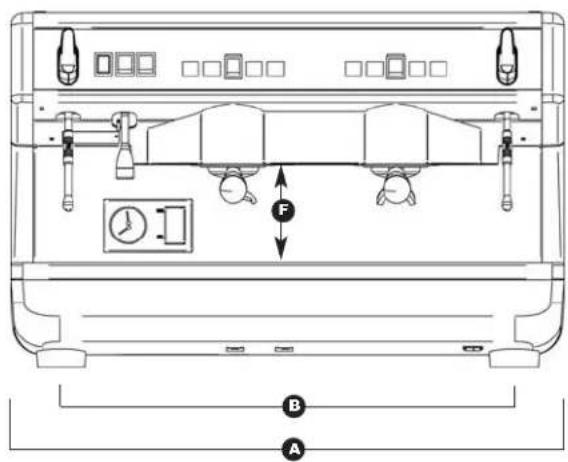
E D C| 2 Gruppi 3 Gruppi | |||||
| PESO NETTO | 60 kg 133 lb 74 kg 163 lb | ||||
| PESO LORDO 65 kg 143 lb 80 kg 176 lb | |||||
| POT. TERMICA | 3000 W | 3000 W | 5000 W | 5000 W | |
| DIMENSIONI 785 mm 30" A | A 78 " 1010 m A 39 | A 78 " | |||
| B 690 mm 27 | B 18 " 920 mm B 6 | B 316 " | |||
| C 545 mm 21 | C 716 " 545 m C 21 | C 716 " | |||
| D 370 mm 14 | D 916 " 370 m D 14 | D 916 " | |||
| E 530 mm 20 | E 1316 " 530 m E 20 | E 1316 " | |||
| F 135 mm 5 | F 18 " 135 mm F | F 18 " | |||

text_image
Appoia® MADE IN ITALYINDICE
CARATTERISTICHE TECNICHE .....2
natural_image
Simple line drawing of a mountainous landscape with a cross symbol and a small object, no text or symbols present.
natural_image
Simple electrical symbol for a lamp or bulb, no text or labels present
natural_image
Simple electrical symbol icon with three parallel lines inside a circle (no text or labels)
natural_image
Illustration of a hand using a cleaning machine to clean air, with no visible text or symbols
natural_image
Simple line drawing of a mountainous landscape with a cross symbol overlay (no text or symbols present)
natural_image
Illustration of hands using a tool to adjust or install a device into a machine (no text or symbols visible)
natural_image
Diagram showing a car interior with a tool, battery, and cleaning components (no text or symbols)natural_image
Close-up of a black mechanical component with a small metallic bolt and mounting bracket (no visible text or symbols)natural_image
Close-up of a hand holding a car battery with directional arrows indicating rotation (no text or symbols)natural_image
Close-up of mechanical components with no visible text or symbolsnatural_image
Close-up of a metallic panel with two circular cutouts and a diamond-patterned floor, labeled 'Fig. 20' (no text or symbols on the panel itself)natural_image
Close-up of industrial piping and valves in a black industrial setting (no visible text or symbols)text_image
Diagram showing installation of a wall socket with an arrow and a switch, alongside a labeled switch with 'O' and 'I'.natural_image
Illustration of a hand using a magnifying glass to adjust a small object, labeled Fig. 25 (no text or symbols on the diagram itself)natural_image
Illustration of a hand inserting a plug into a device panel, with no visible text or symbols.natural_image
Illustration of a hand using a spray gun to clean a cup inside a machine (no text or symbols visible)natural_image
Hand holding a green tool inside a stainless steel kitchen sink (no text or symbols visible)natural_image
Diagram of a cylindrical device with internal components and labeled component D, shown in Fig. 35 (no text or symbols on the device itself)By purchasing the you have made an excellent choice.
The purchase of a professional espresso coffee-maker involves various elements of selection: the name of the manufacturing firm, the machine's specific functions, its technical reliability, the option of immediate and suitable servicing, its price. You certainly evaluated all these factors and then made your choice: the Appia model.
We think you have made the best choice and after every coffee and cappuccino you will be able to assess this.
You will see how practical, convenient and efficient working with Appia is.
If this is the first time you have bought a Nuova Simonelli coffee machine, welcome to high quality coffee-making; if you are already a customer of ours, we feel flattered by the trust you have shown us.
Thanks of the preference.
With best wishes,
natural_image
Exterior view of a modern coffee machine with black and silver casing (no visible text or symbols)
text_image
Appia® MADE IN ITALYTECHNICAL CHARACTERISTICS

text_image
Technical diagram of a portable alarm device with labeled parts and directional arrows indicating force application.
text_image
E D C| 2 Groups 3 Groups | ||||
| NET WEIGHT | 60 kg 133 lb | 74 kg 163 lb | ||
| GROS WEIGHT 65 kg | 143 lb 80 kg 176 lb | |||
| POWER 3000 W 3000 W 5000 W 5000 W | ||||
| DIMENSIONS 785 mm | A | A 78 " 1010 m A89 | A 78 " | |
| B 690 mm 27 | B 18 " 920 mm B6 | B 316 " | ||
| C 545 mm 21 | C 716 " 545 m C21 | C 716 " | ||
| D 370 mm 14 | D 916 " 370 m D14 | D 916 " | ||
| E 530 mm 20 | E 1316 " 530 m E20 | E 1316 " | ||
| F 135 mm 5 | F 18 " 135 mm F | F 18 " | ||

text_image
Appia® MADE IN ITALYINDEX
TECHNICAL CHARACTERISTICS .....24
- DESCRIPTION 27
1.1 ACCESSORIES LIST ....28
-
SAFETY PRESCRIPTION .....29
-
TRANSPORT AND HANDLING .....32
3.1 MACHINE IDENTIFICATION 32
3.2 TRANSPORT 32
3.3 HANDLING 32
- INSTALLATION AND PRELIMINARY
OPERATIONS 33
- ADJUSTMENTS TO BE MADE BY A
QUALIFIED TECHNICIAN ONLY .....34
5.1 PRESSURE SWITCH ADJUSTMENT 34
5.2 PUMP ADJUSTMENT 34
5.3 HOT WATER ECONOMISER ADJUSTMENT (optional V/ESSE model) 35
5.4 PUSH-BUTTONPANEL REPLACEMENT ....35
- USE 36
6.1 APPIA V 36
6.1.1 SWITCHING THE MACHINE ON 36
6.1.2 SWITCHING THE MACHINE OFF 36
6.2 APPIA ESSE 36
6.2.1 SWITCHING THE MACHINE ON 36
6.2.2 SWITCHING THE MACHINE OFF 36
6.3 SELECTION CONFIGURATION ....36
6.4 MAKING COFFE 37
6.5 USING STEAM 37
6.6 MAKING CAPPUCCINO 37
6.7 HOT WATER SELECTION 37
- PROGRAMMING APPIA V .....38
7.1 PROGRAMMING DOSES 38
7.2 PROGRAMMING COFFEE DOSES 38
7.3 PROGRAMMING HOT WATER 38
7.4 PROGRAMMING THE CUP WARMER (optional) ....38
7.5 PROGRAMMING STANDARD DOSES .....39
7.6 COPYING DOSE SETTINGS 39
7.7 PROGRAMMING OPERATING PARAMETERS .....39
- CLEANING AND MAINTENANCE .....41
8.1 STOPPING THE MACHINE 41
8.2 CLEANING THE OUTSIDE OF THE MACHINE .....41
8.3 CLEANING THE STAINLESS COFFEE-HOLDERS ...41
8.4 CLEANING THE UNIT WITH THE AID OF THE BLIND FILTER ....41
8.5 CLEANING FILTERS AND FILTER-HOLDERS .....41
8.6 RESIN AND SOFTENER REGENERATION .....42
- APPIA V MACHINE FUNCTION MESSAGES....43
ELECTRIC SYSTEM APPIA ESSE2/3 GR 46
ELECTRIC SYSTEM APPIA V 2 GR. 48
ELECTRIC SYSTEM APPIA V 3 GR. ....50
PLUMBING SYSTEM ....52
Appia® MADE IN ITALY
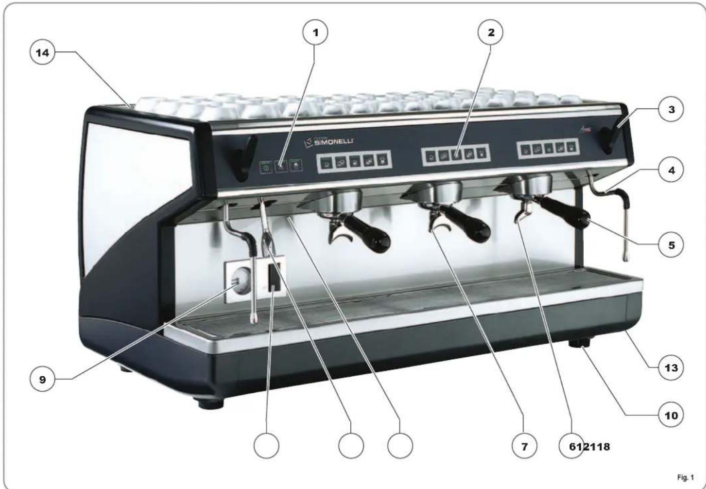
1. DESCRIPTION V - Esseia
text_image
14 1 2 3 4 5 612118 7 9 10 13 14 SIMONELLIKEY
1 Select buttons
2 Delivery buttons
3 Steam knob
4 Steam nozzle
5 Filter holder
6 Single delivery spout
7 Double delivery spout
8 Optical level
9 Pressure gauge
10 Adjustable foot
11 Hot water nozzle
12 Rating plate
13 Main switch
14 Cup warmer (optional)
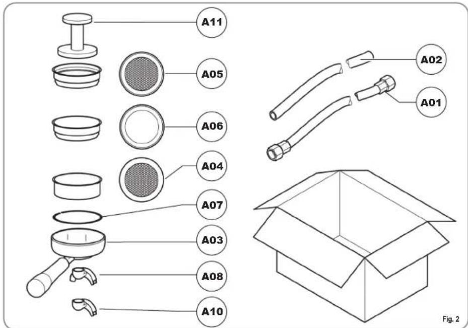
1.1 ACCESSORIES LIST
text_image
A11 A05 A06 A04 A07 A03 A08 A10 A02 A01 Fig. 2| CODE DESCRIPTION 2 GROUPS 3 GROUPS | |||
| A01 Filling tube 38'' 1 1 | |||
| A02 Waste pipe ∅ 25 mm - L. 150 cm 1 1 | |||
| A03 Filter-holder 3 4 | |||
| A04 Double filter 2 3 | |||
| A05 Single filter 1 1 | |||
| A06 Blind filter 1 1 | |||
| A07 Spring 3 4 | |||
| A08 Double delivery spout 2 3 | |||
| A09 Single delivery spout 1 1 | |||
| A10 Coffee presser 1 1 | |||
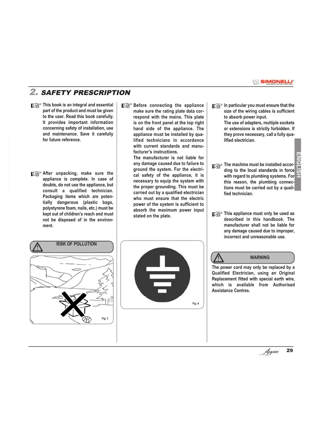
2. SAFETY PRESCRIPTION

This book is an integral and essential part of the product and must be given to the user. Read this book carefully. It provides important information concerning safety of installation, use and maintenance. Save it carefully for future reference.

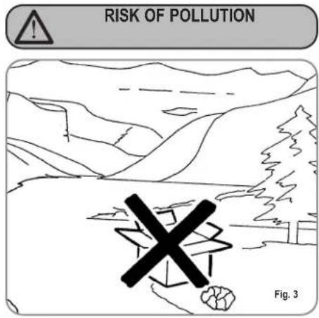
After unpacking, make sure the appliance is complete. In case of doubts, do not use the appliance, but consult a qualified technician. Packaging items which are potentially dangerous (plastic bags, polystyrene foam, nails, etc.) must be kept out of children's reach and must not be disposed of in the environment.
text_image
RISK OF POLLUTION Fig. 3
Before connecting the appliance make sure the rating plate data correspond with the mains. This plate is on the front panel at the top right hand side of the appliance. The appliance must be installed by qualified technicians in accordance with current standards and manufacturer's instructions.
The manufacturer is not liable for any damage caused due to failure to ground the system. For the electrical safety of the appliance, it is necessary to equip the system with the proper grounding. This must be carried out by a qualified electrician who must ensure that the electric power of the system is sufficient to absorb the maximum power input stated on the plate.
natural_image
Pure electrical circuit symbol for a lamp, no text or labels present
In particular you must ensure that the size of the wiring cables is sufficient to absorb power input.
The use of adapters, multiple sockets or extensions is strictly forbidden. If they prove necessary, call a fully qualified electrician.

The machine must be installed according to the local standards in force with regard to plumbing systems. For this reason, the plumbing connections must be carried out by a qualified technician.

This appliance must only be used as described in this handbook. The manufacturer shall not be liable for any damage caused due to improper, incorrect and unreasonable use.

WARNING
The power cord may only be replaced by a Qualified Electrician, using an Original Replacement fitted with special earth wire, which is available from Authorised Assistance Centres.

Basic rules must be observed when using any electric appliance.
In particular:
• do not touch the appliance when hands or feet are wet;

CAUTION RISK OF ELECTRIC SHOCK
• do not use the appliance when barefoot;
• do not use extensions in bath or shower rooms;
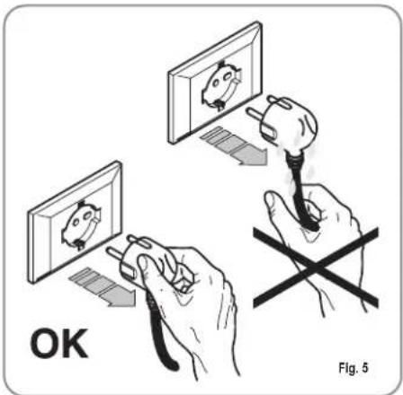
- do not pull the supply cord out of the socket to disconnect it from the mains;
text_image
OK Fig. 5• do not leave the appliance exposed to atmospheric agents (rain, sun, etc.);
• do not let the appliance be used by children, unauthorised staff or staff who have not read and fully understood the contents of this handbook.

Before servicing the appliance, the authorised technician must first switch off the appliance and remove the plug.
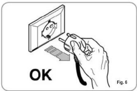
text_image
OK Fig. 6
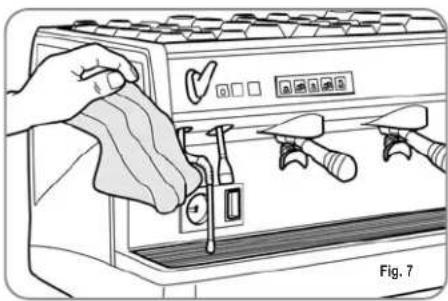
For all cleaning operations comply exclusively with the instructions given in this booklet.
natural_image
Illustration of a hand washing a microwave oven with tools and a checkmark (no text or symbols)
If the appliance breaks down or fails to work properly, switch it off. Any intervention is strictly forbidden. Contact qualified experts only. Repairs should only be made by the manufacturer or authorized service centres. Only original spare parts must be used. Failure to observe the above, could make the appliance unsafe.

For installation, the qualified electrician must fit an omnipolar switch in accordance with the safety regulations in force and with 3 (0,12) or more mm (in) between contacts.

To avoid dangerous overheating, make sure the supply cord is fully uncoiled.

Do not obstruct the extraction and/or dissipator grids, especially of the cup warmer.

The user must not replace the appliance supply cord. If the cord is damaged, switch off the appliance and have a qualified technician change the cord.

If no longer using the appliance, we recommend making it inoperative; after removing the plug from the mains electricity, cut the power supply cable.

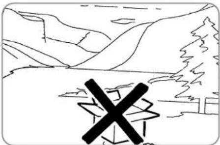
CAUTION RISK OF POLLUTION

Do not dispose of the machine in the environment: to dispose of the machine, use an authorised centre, or contact the manufacturer for relative information.
natural_image
Simple line drawing of a mountainous landscape with a cross symbol overlay (no text or symbols present)
CAUTION RISK OF INTOXICATION

Use the steam nozzle with care and never place hands below the jet of steam. Do not touch the nozzle immediately after use.
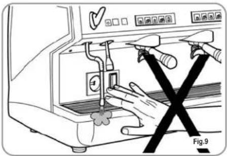
natural_image
Illustration of hands using a tool to clean or install a machine component, no text or symbols present
CAUTION RISK OF BURNS OR SCALDING

We remind you that before carrying out any installation, maintenance, unloading or adjustment operations, the qualified operator must put on work gloves and protective footwear.
3. TRANSPORT AND HANDLING
3.1 MACHINE IDENTIFICATION
Always quote the machine serial number in all communications to the manufacturer, Nuova Simonelli.
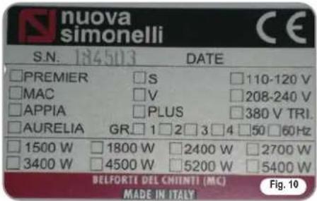
text_image
nuova simonelli S.N. 184503 DATE □PREMIER □S □110-120 V □MAC □V □208-240 V □APPIA □PLUS □380 V TRI. □AURELIA GR□1□2□3□4□50□60Hz □1500 W □1800 W □2400 W □2700 W □3400 W □4500 W □5200 W □5400 W BELFORTE DEL CHIINTI (MC) MADE IN ITALY Fig. 103.2 TRANSPORT
The machine is transported on pallets which also contain other machines - all boxed and secured to the pallet with supports.
Prior to carrying out any transport or handling operation, the operator must:
- put on work gloves and protective footwear, as well as a set of overalls which must be elasticated at the wrists and ankles.
The pallet must be transported using a suitable means for lifting (e.g., forklift).
3.3 HANDLING

CAUTION
RISK OF IMPACT OR CRASHING
During all handling operations, the operator must ensure that there are no persons, objects or property in the handling area.
The pallet must be slowly raised to a height of 30 cm (11,8 in) and moved to the loading area. After first ensuring that there are no persons, objects or property, loading operations can be carried out.
Upon arrival at the destination and after ensuring that there are no persons, objects or property in the unloading area, the proper lifting equipment (e.g. forklift) should be used to lower the pallet to the ground and then to move it (at approx. 30 cm (11,8 in) from ground level), to the storage area.

CAUTION
RISK OF IMPACT OR CRASHING
Before carrying out the following operation, the load must be checked to ensure that it is in the correct position and that, when the supports are cut, it will not fall.
The operator, who must first put on work gloves and protective footwear, will proceed to cut the supports and to storing the product. To carry out this operation, the technical characteristics of the product must be consulted in order to know the weight of the machine and to store it accordingly.
4. INSTALLATION AND PRELIMINARY OPERATIONS
After unpacking, assess that the machine and its accessories unit are complete, then proceed as follows:
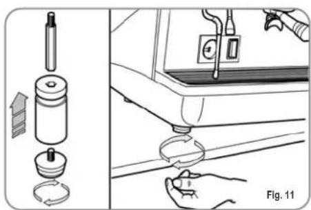
- place the machine so that it is level on a flat surface;
- assemble its supporting feet by inserting the insert into the cylindrical unit;
- twist the rubber foot into the screw thread inside the unit;
- screw the whole assembled unit into the allotted setting for the machine's adjustable feet;
• level the machine by regulating the adjustable feet;
NOTE: the unit grooves have to face upwards, as shown in the following illustration.
natural_image
Diagram showing a car dashboard with tool and cleaning components, no text or symbols presentIt is advisable to install a softener (1) and then a mesh filter (2) on the external part of the plumbing system, during preliminaries and after levelling the machine.
In this way impurities like sand, particles of calcium, rust etc will not damage the delicate graphite surfaces and durability will be guaranteed. Following these operations, connect the plumbing systems as illustrated in the following figure.
Avoid throttling in the connecting tubes. Assess that the drain pipe (3) is able to eliminate waste.
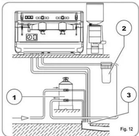
text_image
1 2 3 Fig. 12KEY
1 Softener
2 Mesh filter
3 Drain ∅ 50 mm
NOTE: For a correct functioning of the machine the water works pressure must not exceed 4 bars.
Otherwise install a pressure reducer upstream of the softener; the internal diameter of water entrance tube must not be less than 6mm (3/8").

The machine must always be protected by an automatic omnipolar switch of suitable power with contact openings of equal distance or more than 3mm.
Nuova Simonelli is not liable for any damage to people or objects due to not observing current security measures.
Prior to connecting the machine to the electrical mains, assess that the voltage shown on the machine's data plate corresponds with that of the mains.
If it does not, carry out the connections on the basis of the available electrical line, as follows:
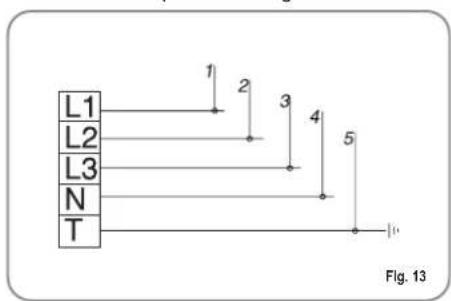
• for V 380 / 3 phases voltage +Neutral:
text_image
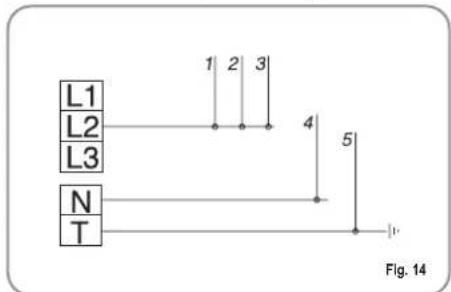
L1 L2 L3 N T 1 2 3 4 5 Fig. 13• for V 230 / monophase voltage
text_image
L1 L2 L3 N T 1 2 3 4 5 Fig. 14KEY
1 Black
2 Grey
3 Brown
4 Blue
5 Yellow-green
5. ADJUSTMENTS TO BE MADE BY A QUALIFIED TECHNICIAN ONLY

CAUTION
The adjustments listed here below must ONLY be performed by a Specialist Technical Engineer.
Nuova Simonelli cannot be held liable for any damage to persons or property arising from failure to observe the safety instructions supplied in this manual.

CAUTION ELECTRIC SHOCK HAZARD
Before performing any operation, the specialist technical engineer must first switch off the main switch off and unplug the machine.
5.1 FILLING BOILER MANUALLY
All models Appia are equipped with a level gauge to keep the water level inside the boiler constant.
When using the machine for the first time, it is advisable to fill the boiler by hand to avoid damaging the electrical resistor and turning on the electronic protection.
If this should happen, just turn the machine off and then start it up again to complete its loading procedure (see chapter "MACHINE FUNCTIONS MESSAGE – LEVEL ERROR").
To fill the boiler manually for the first time, proceed as follows:
- remove the worktop grid;
- turn the manual "A" level tap so that water will enter the boiler;
- once the maximum level has been reached, as indicated by the optical level, turn tap "A" off;

text_image
A MAX MIN Fig. 15- switch the machine on by placing the general switch on "I"; this will activate the level gauge which will automatically maintain the water level inside the boiler.
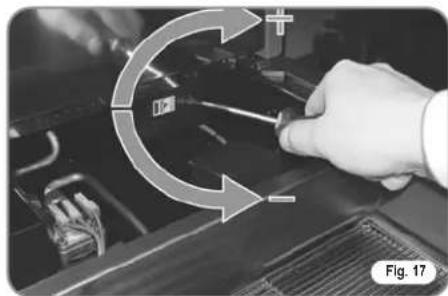
5.2 PRESSOSTAT/PUMP ADJUSTMENT
To adjust the service pressure of the boiler, thus regulating the water temperature, according to the various functions and needs of the coffee desired, proceed as follows:
- remove the worktop grid cover;
- remove the protective metal sheet by unscrewing the two side screws (A) as shown in the following illustration;
natural_image
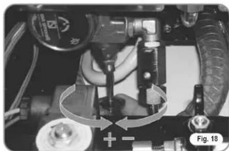
Close-up of a black mechanical component with a metallic bolt and mounting bracket (no visible text or symbols)- turn the pump registration screw, turning it clockwise to INCREASE and counter clock wise to DECREASE the pressure.
natural_image
Close-up of a hand holding a tool with directional arrows indicating motion or cycle (no text or symbols visible)Advisable pressure: 1 - 1,4 bar (according to the kind of coffee).
- turn the pump registration screw, turning it clockwise to INCREASE and counter clock wise to DECREASE the pressure.
natural_image
Close-up of mechanical components with no visible text or symbolsAdvisable pressure: 9 bar.
- The set pump pressure is shown on the lower part of the gauge.
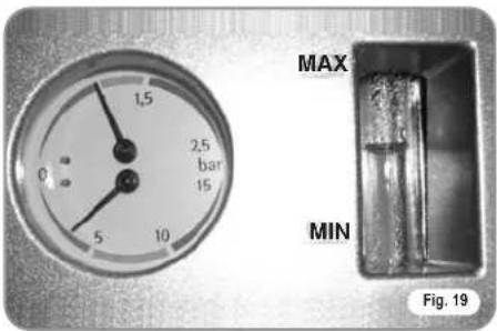
text_image
MAX MIN Fig. 19Once the adjustment operation has been completed, screw the protective metal sheet back into its setting and replace the worktop grid cover.
5.3 HOT WATER ECONOMISER ADJUSTMENT (optional V/ESSE model)
All models are fitted with a hot water mixer that can be used to adjust the delivery temperature of the water and therefore, to optimise system performance.
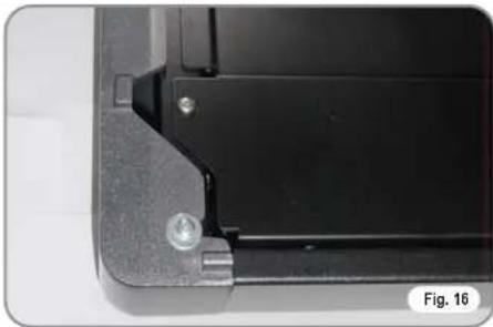
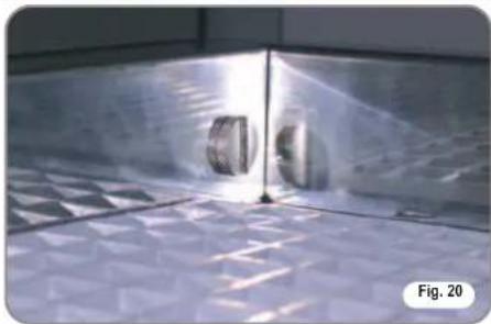
To adjust the hot water economiser, it is necessary to remove the left-hand panel of the machine, proceeding as follows:
- loosen the two top screws (Fig. 20);
natural_image
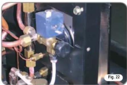
Close-up of a metallic industrial component with two circular holes, placed on a textured floor (no visible text or symbols)- loosen the screw beside the steam nozzle A; - press the knob B and remove the left-hand panel.
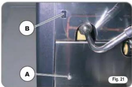
text_image
B A Fig. 21- to adjust the temperature of the hot water delivered from the nozzle, turn the register knob CLOCKWISE / ANTICLOCKWISE to INCREASE / REDUCE the temperature;
natural_image
Close-up of industrial piping and valves in a black industrial setting (no visible text or symbols)- when this operation is complete, fit the left-hand panel back onto the machine.
5.4 PUSH-BUTTON PANEL REPLACEMENT
For correct functioning of the machine, personalising each button panel card at time of replacement is necessary; proceed as follows on the selectors placed on the card (on the key side).
| GROUPS | sw1 | sw1 | sw1 | sw1 | sw1 | sw1 | sw1 | sw1 |
| Group 1 On | Off | Off | Off | On | Off | Off | Off | |
| Group 2 Off | On | Off | Off | Off | On | Off | Off | |
| Group 3 Off | Off | On | Off | Off | Off | On | Off | |
| Group 4 Off | Off | Off | On | Off | Off | Off | Off |
6. USE
Before starting to use the appliance, the operator must be sure to have read and understood the safety prescriptions contained in this booklet.
6.1 APPIA V
6.1.1 SWITCHING THE MACHINE ON
- Plug the machine into the mains power socket.
- Set the main switch (no. 13, Fig 1) to "ON".
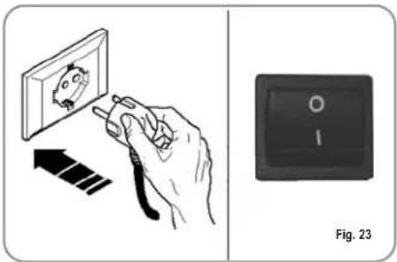
text_image
Fig. 23The LED of the on key will begin to flash.
Hold down the on key for 5 seconds.
At this point, the Flash-test will begin; this is where all LEDs are switched on for three seconds, after which the test is complete and the hot water key will switch off.
The fact that the machine is operating is shown by the LED of the on switch and all delivery keys, which remain lit.
NOTE: all selection keys are enabled from the end of the diagnostic operation.

WARNING
When servicing the electronic machine card, switch off the machine using the external main switch and unplug the power cord.
6.1.2 SWITCHING THE MACHINE OFF
• To switch off the machine, hold down the on/off key for about 2 seconds.
The machine will switch off and the LED on the on/off key will start to flash again.
- Set the main switch to "OFF".
6.2 APPIA ESSE
6.2.1 SWITCHING THE MACHINE ON
- Plug the machine into the mains power socket and set the main switch to "I".
6.2.2 SWITCHING THE MACHINE OFF
- Set the main switch to "O".
6.3 SELECTION
CONFIGURATION
Set the desired function on the available keys placed above the filter-holders (see chapter "DESCRIPTION").
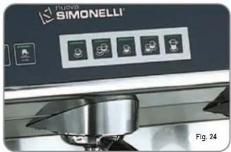
text_image
FUOVA SIMONELLI Fig. 24BUTTONS KEY
(Selection configuration)

1 small coffee

2 small coffees

1 long coffee

2 long coffees

Continuous
6.4 MAKING COFFEE
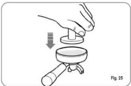
Unhitch the filter-holder and fill it with one or two doses of ground coffee depending on the filter used.
natural_image
Illustration of a hand using a magnifying glass to adjust a small object, labeled Fig. 25 (no text or symbols on the diagram itself)Press the coffee with the provided coffee presser, dust off any coffee residue from the rim of the filter (this way the rubber gasket will last longer).
Insert the filter in its unit.
Press the desired coffee button:

1 small coffee

2 small coffees

1 Caffè lungo

2 long coffees
By starting up the coffee brewing procedure the unit's pump is activated and the unit's solenoid valve is opened.
By pressing it, the button will turn on and signal the operation
NOTE: when in pause, leave the filter-holder inserted in the unit so that it will keep warm. To guarantee the utmost thermic stability during use, the delivery units are thermo-compensated with complete hot water circulation.
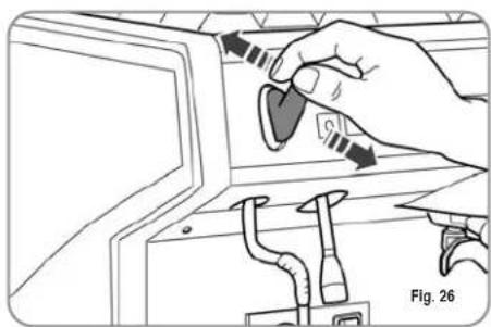
6.5 USING STEAM

CAUTION RISK OF BURNS OR SCALDING
While using the steam nozzle, you must pay attention to not place your hands beneath it or touch just after it has been used.
To use steam just pull or push the provided lever (Fig. 26).
By pulling it completely the lever will hold a position of maximum delivery; by pushing it, the lever will automatically give way.
The two steam nozzles are articulated to guarantee their easy use.
natural_image
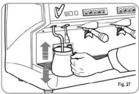
Illustration of a hand inserting a plug into a device panel, with no visible text or symbols6.6 MAKING CAPPUCCINO
To obtain the typical cappuccino foam, immer-se the nozzle all the way into a container 1/3
full of milk (preferably cone-shaped). Turn on the steam. Before the milk starts to boil, pull the nozzle slightly up and lightly move it vertically across the surface of the milk. When you have completed the procedure, clean the nozzle carefully with a soft cloth.
natural_image
Illustration of a hand using a coffee maker to lift a cup, with arrows indicating motion (no text or symbols)6.7 HOT WATER SELECTION

CAUTION RISK OF BURNS OR SCALDING
While using the hot water nozzle, pay careful attention not to place your hands beneath it or touch it just after it has been used.
This nozzle delivers hot water to make tea or herb teas.
Place a container underneath the hot water nozzle and press the switch (ESSE model) or press the hot water select button (V model).
Make sure the button lights up.
Water will be delivered from the hot water nozzle for as long as the set time indicates.
NOTE: Hot water can be delivered at the same time as coffee.
7. PROGRAMMING Appia V
7.1 PROGRAMMING DOSES
To access the programming units, proceed as follows:
NOTE: the procedure can be carried out with the machine on.
• To enter the programming function for each group, it is necessary to hold down the continued delivery key for 5 seconds

• The delivery keys will begin to flash.
- Accessing the programming mode for the first group also enables the setting mode for the machine's operating parameters.
7.2 PROGRAMMING COF-FEE DOSES
To programme the amount of water for each of the delivery keys, proceed as follows:
- fill the filter holder with the right amount of coffee (the double or single filter holder can be used, according to the key to be programmed).
- Place the filter holder in the group.
- Press one of the delivery keys:


- The machine will begin to dispense and once the required quantity has been delivered, press the continued key.

- Delivery will cease and the selected dose key will switch off (the other keys will continue to flash).
- Press the continued key to exit the programming function or to continue programming other dose keys
NOTE: This procedure can be used for all groups on the machine, although it must be performed on one group at a time; the other groups will continue to operate as normal.
7.3 PROGRAMMING HOT WATER
- Use the relevant procedure to enter the programming function.
- Press the hot water selection key
• Hot water delivery will begin.
- Decide the required amount of hot water and then press the key again


- Press the continued key to exit the programming function or to continue programming other selection keys.
7.4 PROGRAMMING THE CUP WARMER (optional)
- Enter the programming mode for the first group following the usual procedure.
- Press the cup warmer select key

• The delivery buttons for the first and second group will respectively show the automatic switch on and off times, while the continuous keys for the first and second group
will flash.
As shown in the table, each of the delivery keys has an associated value; the switch on time for the cup warmer is given by summing the values for the lit keys of the first group. The same calculation method is used for the switch off time of the cup warmer, using the keys of the second group.
| Key | Group 1(on time) | Group 2(off time) |


2 min. 5 min.
4 min. 10 min.
8 min. 20 min.
16 min. 40 min.
7.5 PROGRAMMING STAN- DARD DOSES
- It is possible to enter pre-set values for the 4 group doses and water (steam).
To do this, it is necessary to press the key and hold it down for at least 10
seconds until the flashing keys switch off.
The doses are:
| 1CN 2 | CN 1CL 2CL | |
| 40 cc 6 | 0 cc 50 cc 85 cc |
| WATER |
| 9 sec. |
NOTE: A time setting of 0 seconds for steam and water means this function will work continually.
7.6 COPYING DOSE SETTINGS
It is possible to copy the dose settings for group 1 to groups 2 or 3.
To do this, hold down the continuous key of the group 2 or 3 for at least 8
seconds until the keys stop flashing.
7.7 PROGRAMMING OPERATING PARAMETERS

CAUTION
The adjustments listed here below must ONLY be performed by a Specialist Technical Engineer
If you hold down the key of the second group, after first entering the programming mode for the first group, this will access the machine parameters setting mode; this is signalled by the continuous key for
the second group, which will switch on.
- Enabling the pump if the level is enabled.
- Enabling the software block to enter the dose programming function.
- Adjusting keypad brightness.
- Enabling the hot water pump (on machines fitted with economiser).
- Disenabling the cup warmer
- Restoring default settings.
1. Enabling the pump during levelling.
Use the espresso key to set pump enabling during levelling:
if the key is lit, the pump is enabled
together with the level; if it is switched off, the pump is not enabled with the level function.
- Enabling the software block to enter the dose programming function.
Use the long coffee key to enable a software block to programme doses (key lit) or to de-activate the block (key off).
3. Adjusting keypad brightness..
The 2 long coffees key of the second group is used to choose the key brightness setting from 5 pre-set levels.
Use the key, which will flash, to change the level, lowering it to minimum or returning it to maximum.
4. Enabling the hot water pump (machines fitted with economiser only).
Use the hot water key to set the pump to switch on while hot water is being delivered.
If the 📄 key is lit, the pump will switch on while hot water is being delivered; if it is switched off, the pump will not switch on.
5. Disenabling the cup warmer..
Use the key to enable or disenable cup warmer operation. If the key is lit, the cup warmer will operate normally as set during programming; if the key is switched off, the cup warmer is disenabled.
If the cup warmer is not enabled, the

key will only switch on during the Flash-test, after which this key will have no effect when pressed.
Press the continuous key of the second group to store the modified values and exit the page for setting machine operating parameters.
6. Restoring default settings
It is possible to restore default settings, i.e. pump level, water with pump, maximum brightness and cup warmer enabled.
To restore these parameters, it is sufficient to switch on the machine using the key
then to press the 2 espressos

long coffees keys of the first group at

the same time.
7.8 AUTOMATIC GROUP CLEANING CYCLE
To enter the automatic cleaning mode, switch the machine off and then on again, holding down the hot water and cup warmer
keys during the initial Flash-test.
At the end of the Flash-test, the and keys and the single long coffee key


of all groups will begin to flash.

Press the key to start the washing cycle for the relevant group.
Once the washing cycle has been completed, it is possible to perform a rinse cycle for the same group by pressing the key again.

To perform the rinse cycle at a later time, switch off the machine and the card will store any cleaning cycles that need to be completed in its memory. In fact, the next time that the machine is switched on, the machine card will automatically open the group cleaning status without it being necessary to press the and keys.


Hold down the and keys for 2 seconds to exit the cleaning mode in the event that there are no cycles to be completed. For incomplete cycles, the keys of the


groups that require rinsing will continue to flash.
Hold down the and keys for 2 seconds more to force exit from the cleaning mode, resetting all information about rinse cycles still to be completed.
When a cleaning cycle is complete, the key for the group will switch off.

If there are no more rinse cycles to be performed, the card will exit the cleaning mode.
8. CLEANING AND MAINTENANCE
8.1 STOPPING THE MACHINE
To stop the machine, press the main switch and set it to OFF.
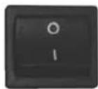
Fig. 28
8.2 CLEANING THE OUTSIDE OF THE MACHINE
Before performing any cleaning operation, the machine must be cut off from the power supply (machine switched off and unplugged).
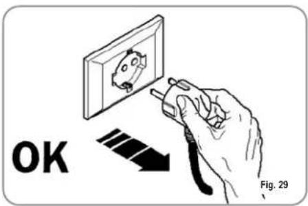
text_image
OK Fig. 29
WARNING
Do not use solvents, chlorine-based products or abrasives.
Cleaning the work area: remove the worktop, lifting it up from the front and sliding it out. Remove the water collection dish underneath and clean everything with hot water and cleansers.
Cleaning the bottom: To clean all the chromium-plated areas, use a soft, damp cloth.
8.3 CLEANING THE STAIN- LESS COFFEE-HOLDERS
The stainless coffee-holders are situated under the delivery units, as shown in figure.
natural_image
Hand holding a green tool inside a metallic bowl (no visible text or symbols)NOTE: To clean proceed as follows:
- Turn the screw placed in the centre of the coffee-holder.
- Slide the coffee-holder out and check that its holes are not obstructed but clean.
- If obstructed, clean as described (Paragraph "CLEANING FILTERS AND FILTER-HOLDERS")
We recommend cleaning the coffee-holder once a week.
8.4 CLEANING THE UNIT WITH THE AID OF THE BLIND FILTER
The machine is pre-set for cleaning the delivery unit with a specific washing powder.
We recommend carrying out a washing cycle at least once a day with special cleansers.

CAUTION RISK OF INTOXICATION
Once the filter-holder has been removed, repeat delivery operations a few times to eliminate any cleanser residues.
To carry out the washing procedure, proceed as follows:
1) Substitute the filter with the delivery unit blind filter.
2) Fill it with two spoonfuls of special cleanser powder and insert it into the unit filter-holder.
3) Press one of the coffee keys and halt it after 10 seconds.
4) Repeat the procedure several times.
5) Remove the filter-holder and carry our a few deliveries.
8.5 CLEANING FILTERS AND FILTER-HOLDERS
Place two spoonfuls of special cleanser in half a litre of hot water and immerse filter and filter-holder (without its handle) in it leaving them to soak for at least half an hour. Then rinse abundantly with running water.
8.6 RESIN AND SOFTENER REGENERATION
To avoid scaling deposits in the boiler and in the heating exchangers, the softener must always be kept efficient. Therefore, the ionic resins must be regularly regenerated.
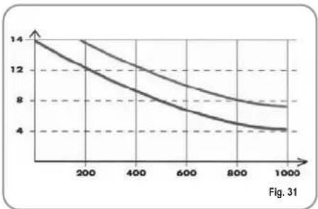
Regeneration times are established according to the quantity of coffee delivered daily and the hardness of the water utilised.
As an indication, regeneration times can be calculated on the basis diagram illustrated in Fig. 31.
line
| x | y1 | y2 | | ---- | ---- | ---- | | 0 | 14.0 | 14.0 | | 200 | 12.0 | 13.0 | | 400 | 10.0 | 11.5 | | 600 | 8.0 | 9.5 | | 800 | 6.5 | 8.0 | | 1000 | 5.0 | 7.0 |Regeneration procedures are as follows:
1) Turn the machine off and place a container large enough to contain at least 5 litres under tube E (Fig. 32).
Turn levers C and D from left to right; take the cap off by unscrewing knob and fill with 1 Kg normal kitchen salt (Fig. 33).
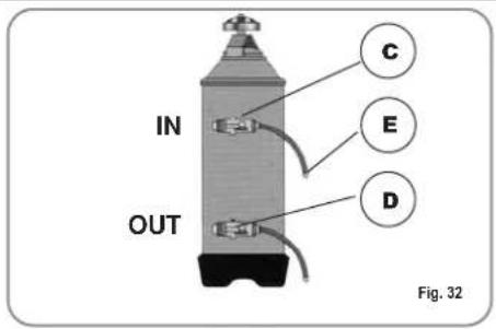
text_image
IN OUT C E D Fig. 32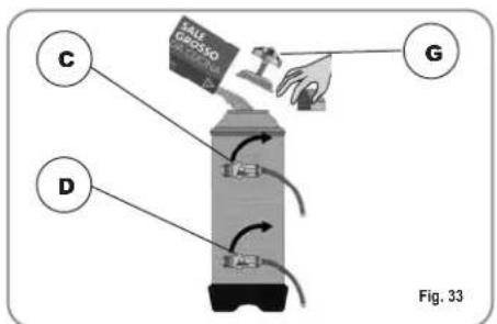
text_image
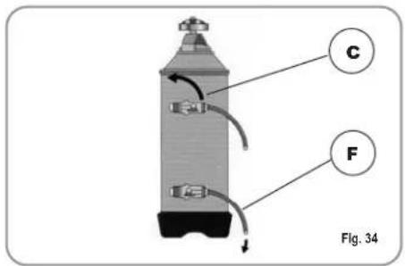
AUTO GROSSO A B C D Fig. 332) Put the cap back on and reposition lever C moving it towards the left (Fig. 34) and allowing tube F to discharge the salty water until it has been eliminated and the water becomes fresh again (about half and hour).
text_image
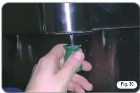
C F Fig. 343) Reposition lever D towards the left (Fig. 35).
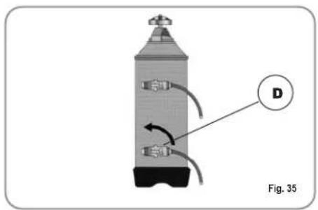
natural_image
Diagram of a cylindrical device with internal components and labeled component D, shown in Fig. 35 (no text or symbols on the device itself)9. Appia V MACHINE FUNCTION MESSAGES
| DISPLAY AND KEY INDICATIONS | CAUSE | EFFECT | SOLUTION | NOTES |
Drawing of continued key  hing and delivery key hing and delivery key  | If the doser doesn't send out its set commands within the first three seconds from delivery onset. | If the delivery isn't manually halted, the maximum time limit (120 sec) will be blocked. | Interrupt delivery. | |
Drawing of continued key flashing.  | If within 90 sec. from onset, with pump inserted during the levelling, at 180 sec., if the level has not been re-established. | The pump, the resistor and all the functions will be halted. | Turn the machine off for at least 5 sec. and then switch it on again. |
NOTES:
Félicitations,
natural_image
Exterior view of a modern coffee machine with black and silver casing (no visible text or symbols)
text_image
Appia® MADE IN ITALYCARACTERISTIQUES TECHNIQUES

text_image
Technical diagram of a portable coffee machine with labeled parts and directional arrows indicating flow or movement.
text_image
E D C| 2 Groupes 3 Groupes | |||
| POIDS NET | 60 kg 133 lb 74 kg 163 lb | ||
| POIDS BRUT 65 kg 143 lb 80 kg 176 lb | |||
| PUISS. THERMIQUE | 3000 W 3000 W 5000 W 5000 W | ||
| DIMENSIONS 785 mm | A 78 " 1010 m A 39 | A 78 " | |
| B 690 mm 27 B 18 " 920 mm B 6 | B 316 " | ||
| C 545 mm 21 C 716 " 545 m C 21 | C 716 " | ||
| D 370 mm 14 D 916 " 370 m D 14 | D 916 " | ||
| E 530 mm 20 E 1316 " 530 m E 20 | E 1316 " | ||
| F 135 mm 5 F 18 " 135 mm F | F 18 " | ||

text_image
Appia® MADE IN ITALYINDEX
CARACTERISTIQUES TECHNIQUES ...46
1. DESCRIPTION 49
1.1 LISTE ACCESSOIRES ....50
2. PRESCRIPTIONS DE SECURITE .....51
- TRANSPORT ET DEPLACEMENT .....54
3.1 IDENTIFICATION DE LA MACHINE ....54
3.2 TRANSPORT 54
3.3 DEPLACEMENT ....54
4. INSTALLATION ET OPERATIONS PRELIMINAIRES ....55
7. PROGRAMMATION APPIA V .....60
7.1 PROGRAMMATION DOSES 60
7.2 PROGRAMMATION DOSES CAFFE ....60
7.3 PROGRAMMATION EAU CHAUDE 60
7.4 PROGRAMMATION CHAUFFE-TASSES (OPTION) ...60
7.5 PROGRAMMATION DOSES STANDARD .....61
7.6 COPIAGE DOSES 61
7.7 PROGRAMMATION PARAMETRES
DE FUNCTIONEMENT 61
7.8 CYCLE AUTOMATIQUE DE NETTOYAGE DES GRUPES ....62
8. NETTOYAGE ET ENTRETIEN .....63
8.1 ARRET 63
8.2 NETTOYAGE DE LA CARROSSERIE .....63
8.3 NETTOYAGE DES DOUCHES INOX 63
8.4 NETTOYAGE DU GROUPE AVEC L'AIDE DU FILTRE BORGNE 63
8.5 NETTOYAGE DES FILTRES ET DES SUPPORTS A FILTRES ....63
8.6 REVIVIFICATION DES RESINES DE L'ADOUCISSEUR ....64
9. MESSAGES FONCTIONS MACHINE Appia V 65
INSTALLATION ELECTRIQUE APPIA ESSE 2/3 GROUPES .....112
INSTALLATION ELECTRIQUE APPIA V 2 GROUPES ....114
INSTALLATION ELECTRIQUE APPIA V 3 GROUPES ....116
INSTALLATION HYDRAULIQUE .....118

text_image
Apoia® MADE IN ITALY1. DESCRIPTION V - Essea

text_image
1 2 3 4 5 612118 7 9 10 13 14 SICUATE SIMONELLILEGENDE
natural_image
Simple electrical symbol icon with three parallel lines inside a circle (no text or labels)
natural_image
Illustration of a hand using a tool to adjust a wall-mounted device (no text or symbols present)
natural_image
Illustration of a hand washing a washing machine with tools and a checkmark (no text or symbols)
natural_image
Simple line drawing of a mountainous landscape with a cross symbol overlay (no text or symbols present)
ATTENTION RISQUE D'INTOXICATION

natural_image
Illustration of hands using a tool to clean or install a machine component, no text or symbols present
ATTENTION RISQUE DE BRULURES

3. TRANSPORT ET DEPLACEMENT
3.1 IDENTIFICATION DE LA MACHINE
RISQUE D'IMPACT OU D'ECRASEMENT
RISQUE D'IMPACT OU D'ECRASEMENT
natural_image
Diagram showing a car interior with a tool, battery, and cleaning components (no text or symbols)natural_image
Close-up of a black mechanical component with a metallic screw and mounting bracket (no visible text or symbols)natural_image
Close-up of a hand holding a tool with directional arrows indicating motion or cycle (no text or symbols visible)natural_image
Close-up of mechanical components with no visible text or symbolsnatural_image
Close-up of a metallic panel with two circular cutouts and a textured floor, labeled 'Fig. 20' in the corner (no readable text or symbols on the panel itself)natural_image
Close-up of industrial piping and valves in a black industrial setting (no visible text or symbols)natural_image
Illustration of a hand using a magnifying glass to adjust a small object, labeled Fig. 25 (no text or symbols on the diagram itself)natural_image
Illustration of a hand inserting a plug into a device panel, with no visible text or symbols6.6 PREPARATION DU CAPPUCCINO
natural_image
Illustration of a hand using a spray gun to clean a cup inside a machine (no text or symbols visible)6.7 SELECTION EAU CHAUDE

ATTENTION RISQUE DE BRULURES
natural_image
Hand holding a green tool near a metallic surface, no visible text or symbolsnatural_image
Diagram of a cylindrical device with internal components and labeled component D, shown in Fig. 35 (no text or symbols on the device itself)9. MESSAGES FONCTIONS MACHINE Appia V
natural_image
Exterior view of a modern espresso machine (SIMONELLI) with dual leavers and control buttons (no visible text or symbols on the device itself)
text_image
Appia® MADE IN ITALYtext_image
Technical diagram of a portable coffee machine with labeled parts and directional arrows indicating flow or movement.
text_image
E D C| 2 Gruppen 3 Gruppen | ||||
| NETTOGEWICHT | 60 kg 133 lb 74 kg 163 lb | |||
| BRUTTOGEWICHT | 65 kg | 143 lb | 80 kg | 176 lb |
| HEIZLEISTUNG | 3000 W | 3000 W | 5000 W | 5000 W |
| ABMESSUNGEN 785 | A 30 | A 78 " 1010 m ^A 39 | A 78 " | |
| B 690 mm 27 | B 18 " 920 mm ^B 6 | B 316 " | ||
| C 545 mm 21 | C 716 " 545 m ^C 21 | C 716 " | ||
| D 370 mm 14 | D 916 " 370 m ^D 14 | D 916 " | ||
| E 530 mm 20 | E 1316 " 530 m ^E 20 | E 1316 " | ||
| F 135 mm 5 | F 18 " 135 mm ^F | F 18 " | ||

text_image
Appoia® MADE IN ITALYINHALTSVERZEICHNIS
natural_image
Line drawing of a hand using a cleaning machine to clean air, with no text or symbols present.
natural_image
Simple line drawing of a mountain landscape with a cross symbol and label 'Abb. 8' (no text or symbols in the diagram itself)
text_image
Diagram showing car oil dropers and fuel injection system with labeled componentsnatural_image
Close-up of a black mechanical component with a metallic bolt and mounting bracket (no visible text or symbols)natural_image
Close-up of a hand holding a tool with directional arrows indicating rotation or cycle (no text or symbols visible)natural_image
Close-up of mechanical components with no visible text or symbolsnatural_image
Close-up of a metallic industrial component with two circular holes, placed on a textured floor (no visible text or symbols)natural_image
Close-up of industrial piping and valves in a black industrial setting (no visible text or symbols)natural_image
Illustration of a hand using a magnifying glass to adjust a small object, with no text or symbols present.natural_image
Hand inserting a plug into a device panel, showing electrical connections (no text or symbols)natural_image
Illustration of a person using a coffee maker machine with tools and a coffee cup, no text or symbols presentnatural_image
Hand holding a green tool inside a stainless steel kitchen sink (no text or symbols visible)natural_image
Exterior view of a modern espresso machine (no visible text or symbols)
text_image
Appia® MADE IN ITALYCARACTERÍSTICAS TÉCNICAS

text_image
Technical diagram of a portable coffee machine with labeled parts and directional arrows indicating flow or movement.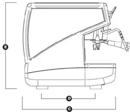
text_image
E D C| 2 Grupos 3 Grupos | ||||
| PESO NETO | 60 kg 133 lb 74 kg 163 lb | |||
| PESO BRUTO 65 kg 143 lb 80 kg 176 lb | ||||
| POT. TÉRMICA | 3000 W | 3000 W | 5000 W | 5000 W |
| MEDIDAS 785 mm 30 | A | A 78 " 1010 m A 39 | A | 78 " |
| B 690 mm 27 | B 18 " 920 mm B 6 | B | 316 " | |
| C 545 mm 21 | C 716 " 545 m C 21 | C | 716 " | |
| D 370 mm 14 | D 916 " 370 m D 14 | D | 916 " | |
| E 530 mm 20 | E 1316 " 530 m E 20 | E | 1316 " | |
| F 135 mm 5 | F 18 " 135 mm F | F | 18 " | |

text_image
Appoia® MADE IN ITALYINDICE
CARACTERISTICAS TECNIVAS .....90
natural_image
Simple electrical symbol icon with three parallel lines inside a circle (no text or labels)
natural_image
Illustration of a hand using a cleaning machine to clean or store items (no text or symbols visible)
natural_image
Simple line drawing of a mountainous landscape with a cross symbol overlay (no text or symbols present)
natural_image
Illustration of hands using a tool to clean or install a machine component, no text or symbols present
ATENCION PELIGRO DE QUEMADURAS

natural_image
Diagram showing a mechanical device and a car interior with hand tool, no text or symbols presentnatural_image
Close-up of a black mechanical component with a metallic bracket and mounting holes (no visible text or symbols)natural_image
Close-up of a hand holding a tool with directional arrows indicating motion or cycle (no text or symbols visible)natural_image
Close-up of mechanical components with no visible text or symbolsnatural_image
Close-up of a metallic duct or pipe with two circular cavities and a textured floor, labeled 'Fig. 20' in the corner (no readable text or symbols on the structure itself)natural_image
Close-up of industrial piping and valves with blue components, no visible text or symbolsnatural_image
Illustration of a hand using a magnifying glass to adjust a small object, labeled Fig. 25 (no text or symbols on the diagram itself)natural_image
Illustration of a hand inserting a plug into a device panel, with no visible text or symbols.natural_image
Illustration of a hand using a spray gun to clean a cup inside a machine (no text or symbols visible)natural_image
Hand holding a green tool inserted into a metallic bowl (no text or symbols visible)natural_image
Diagram of a cylindrical device with internal components and directional arrows, labeled D, shown in Fig. 35 (no text or symbols on the device itself)9. MENSAJES FUNCIONES MÁQUINA Appia V
Cup warmer solenoid valve EVHW
Hot water mixer solenoid valve
EV L
Level solenoid valve
EV1-2-3
Group delivery solenoid valve
PM
Pump motor
Dose
Fan
HE
Heating element
LP
Level probe
TE
Safety thermostat
R
Relay switch
P
Pressure switch
MS
Main switch
TP
Sonda temperatura
LÉGENDE
EVC
Electrovanne chauffe-tasses
EVHW
text_image
Technical schematic diagram of a mechanical or fluid system with numbered components and labeled partsIMPIANTO IDRAULICO /PLUMBING SYSTEM /INSTALLATION HYDRAULIQUE /HYDRAULIKANLAGE /INSTLACIÓN HIDRÁULICA
| LEGENDA | KEY | LÉGENDE | ZEICHENERKLÄRUNG | NOTA |
| 1 Rubinetto ingresso acqua2 Pompa3 Valvola di ritegno4 Valvola di espansione5 Elettrovalvola di livello6 Dosatore volumetrico7 Scambiatore di calore8 Elettrovalvola erogazione9 Valvola di sicurezza cald.10 Rubinetto vapore11 Pressostato12 Caldaia13 Resistenza14 Manometro doppia scala15 Depuratore16 Gruppo erogatore | 1 Water entrance faucet2 Pump3 Retaining valve4 Expansion valve5 Refill electrovalve6 Flowmeter7 Heat exchanger8 Delivery electrovalve9 Heater safety valve10 Steam tap11 Pressostat12 Boiler13 Heating element14 Double scale gauge15 Purifier16 Delivery unit | 1 Robinet arrivée d'eau2 Pompe3 Soupape d'arrêt4 Soupape d'expansion5 Electrovanne de niveau6 Doseur volumétrique7 Echangeur de chaleur8 Electrovanne de distribution9 Soupape de sûreté chaudière10 Robinet vapeur11 Pressostat12 Chaudière13 Résistance14 Manomètre double échelle15 Dépurateur16 Groupe de distribution | 1 Hahn Wassereinlauf2 Pumpe3 Rückschlagventil4 Drosselventil5 Elektroventil Füllstand6 Volumendosierer7 Wärmetauscher8 Elektroventil Ausgabe9 Sicherheitsventil Wärmet.10 Dampfhahn11 Druckwächter12 Kessel13 Widerstand14 DruckmesserDoppelskala15 Reiniger16 Ausgabegruppe | 1 Grifo entrada agua2 Bomba3 Válvula de retención4 Válvula de expansión5 Electroválvula de nivel6 Dosador volumétrico7 intercambiador de calor8 electroválvula de erogación9 Válvula de seguridad caldera10 Grifo vapor11 Presostato12 Caldera13 Resistencia14 Manómetro doble escala15 Depurador16 Grupo erogador |
NOTE / NOTES:
NOTE / NOTES:
NOTE / NOTES:

text_image
nuova SIMONELLI® espresso coffee machinesNuova Distribution Centre LLC 6940Salashan PKWY BLDG A 98248
Ferdale, WA
Tel. +1.360.3662226
Fax +1.3603664015
videoconf.+1.360.3188595