
GP600 - Subwoofer Crunch - Free user manual and instructions
Find the device manual for free GP600 Crunch in PDF.
| Product Type | Amplified subwoofer enclosure |
| Brand | Crunch |
| Model | GP600 |
| Dimensions (L x H x D) | 210 x 76 x 285 mm |
| Weight | 2.5 kg (approx) |
| Power Supply | 12 V (9 – 15 V), negative ground |
| Fuse | 15 A |
| RMS Output Power | 1 x 100 W |
| Max Output Power | 1 x 200 W |
| Speaker | 13 x 20 cm (5" x 8") |
| Adjustable Low-Pass Filter | 50 – 150 Hz |
| Phase | 0° / 180° |
| Adjustable Bass Boost | 0 – 12 dB @ 45 Hz |
| Audio Inputs | RCA and high-level (HI LEVEL) |
| Auto Turn-On | Yes (DC offset detection) |
| Remote Bass Level Control | Yes (included) |
| Protections | Overheating and short circuit (red LED) |
| Maintenance and Cleaning | Clean with a soft, dry cloth. Avoid water and chemicals. |
| Safety | Disconnect the battery before installation. Use a fuse near the battery (distance < 30 cm). |
| Spare Parts and Repairability | Replaceable 15 A fuse. For other repairs, contact a specialist. |
| Installation | Recommended by a specialist. Mount away from shocks, vibrations, dust, and dirt. |
| General Information | Active subwoofer for 12 V audio system. Manual available in several languages. |
Frequently Asked Questions - GP600 Crunch
User questions about GP600 Crunch
0 question about this device. Answer the ones you know or ask your own.
Ask a new question about this device
Download the instructions for your Subwoofer in PDF format for free! Find your manual GP600 - Crunch and take your electronic device back in hand. On this page are published all the documents necessary for the use of your device. GP600 by Crunch.
USER MANUAL GP600 Crunch
natural_image
Black CRUNCH audio amplifier device with visible buttons and speaker grille (no text or symbols on main body)GP600
ACTIVE SUBWOOFER SYSTEM
BENUTZERHANDBUCH
OWNER'S MANUAL
INHALTSVERZEICHNIS TABLE OF CONTENT TABLE DES MATIÈRES SOMMARIO INDICE
flowchart
graph LR
    A["6"] --> B["LOW LEVEL INPUT"]
    B --> C["R"]
    B --> D["L"]
HOCHPEGELEINGÄNGE
AUTOMATISCHE EINSCHALTFUNKTION
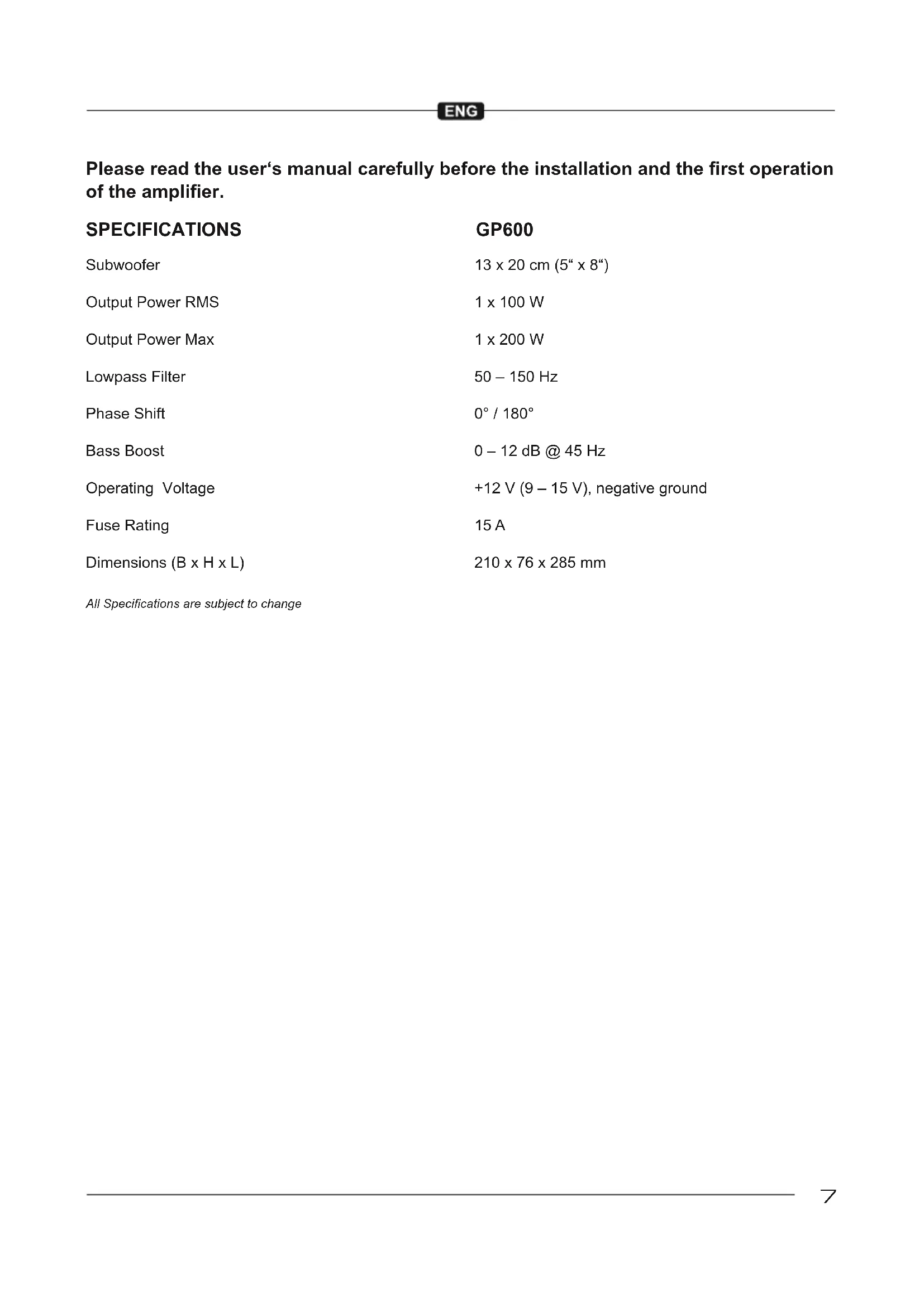
Please read the user's manual carefully before the installation and the first operation of the amplifier.
SPECIFICATIONS
| Subwoofer | 13 x 20 cm (5" x 8") |
| Output Power RMS | 1 x 100 W |
| Output Power Max | 1 x 200 W |
| Lowpass Filter | 50 – 150 Hz |
| Phase Shift | 0° / 180° |
| Bass Boost | 0 – 12 dB @ 45 Hz |
| Operating Voltage | +12 V (9 – 15 V), negative ground |
| Fuse Rating | 15 A |
| Dimensions (B x H x L) | 210 x 76 x 285 mm |
All Specifications are subject to change
IMPORTANT NOTES PRIOR TO INSTALLATION
- This device is only suited for a 12 volt system with negative ground.
- Ensure that the input and output cables are sufficiently separated from the power supply cables. Otherwise interferences may occur.
- Ensure the accessibility of the fuse and the operating elements after installation.
- The reliability and performance of the amplifier depends on the quality of installation. Preferably consult an expert to install the system.
- Avoid any damage or removing of the components of the vehicle like wires, cables, board computer, seat belts, gas tank or the like.
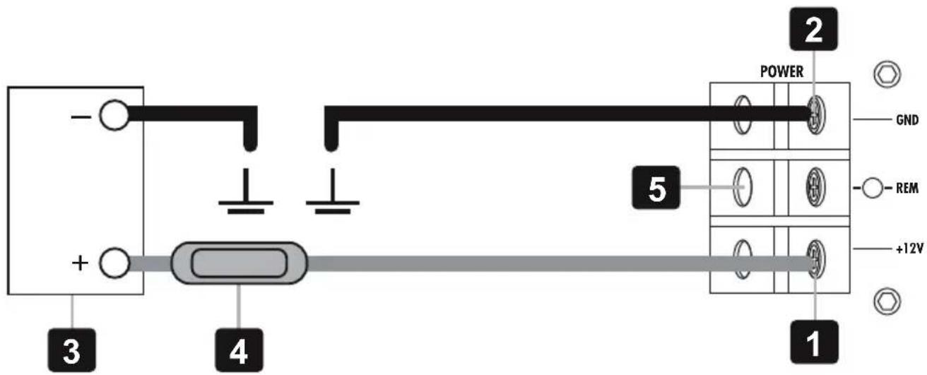
POWER SUPPLY AND TURN-ON-CONNECTION
ATTENTION: Before you start with the installation, disconnect the ground connection from the vehicle's battery in order to prevent short circuits. Use the enclosed cable plug to connect each terminal.
The power wiring which is usually installed in on-board car networks is not sufficient for a power amplifier's demands. Make sure that the power wires to GND and to the +12V terminal has been sufficiently specified.
First connect the GND terminal [1] of the amplifier to an appropriate ground connection at the chassis. To ensure a good connection, residue dirt and dust from the connection point. A loose connection may cause malfunctions or interferences noise and distortion.
Then connect the +12 V terminal [2] of the amplifier with the battery by using an appropriate cable including an in-line fuse. This fuse [4] should be located very close to the battery [3]; for safety reasons not more than 30 cm away. Only insert the fuse when the installation, including the connection of the loudspeakers, has been accomplished.
Then connect the remote turn-on-wire [5] from the head unit with the amplifier's REM terminal. A cable with a cross-section of 0.5 mm^2 is adequate.
AUDIO SIGNAL CABLES
When installing the audio cables between the RCA outputs of the head unit and the RCA inputs of the amplifier [6], the audio and power supply cables should, if possible, not be routed along the same side of the vehicle. We recommend a separated installation, e.g. routing the power cable through the cable channel on the left side and the audio cables through the cable channel of the vehicle on the right side or vice versa. This prevents interferences due to crosstalk into the audio signal.

flowchart
graph LR
    A["6"] --> B["LOW LEVEL INPUT"]
    B --> C["R"]
    B --> D["L"]
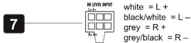
HIGH LEVEL INPUTS & AUTO TURN ON
The high level inputs under HI LEVEL INPUT [7] is suitable to connect the device input with speaker wires, if your head unit is not equipped with pre-amplifier RCA outputs. Extend therefore every regarding speaker cable from your head unit with appropriate speaker cables from your car audio retailer to the mounting location of the amplifier. Then connect the each matching loudspeaker cable with the cables of the included High Level Input jack.
CAUTION: Never use the high level inputs and the RCA inputs at the same time. This may damage the device seriously. Use the enclosed cable plug to connect each terminal.
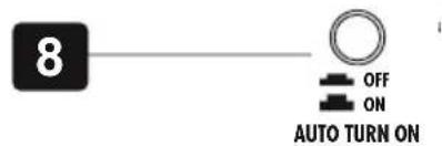
AUTO TURN ON
Push the AUTO TURN ON switch [8] to ON position. The amplifier detects now a voltage rise (6 Volts) over the connected input signal on the HI LEVEL INPUT [7] when the head unit will be switched on. Hence, the amplifier will also be turned on. As soon as the head unit will be turned off, the amplifier turns also automatically off. In this case the turn-on connection [5] is not needed.
NOTE: The AUTO TURN ON function usually works with 90% of all head units, because they are equipped with "High Power"-outputs. Only with a few older and still existing head units the Auto Turn On function is not working.
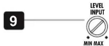
INPUT SENSITIVITY
Turn the LEVEL INPUT [9] controller of the amplifier to the MIN position. Then turn the volume controller of the head unit to 80 - 90% of its full setting. Now turn LEVEL INPUT [9] clockwise until you hear some distortion. Then turn back LEVEL INPUT [9] slightly until you hear a cleaner sound.
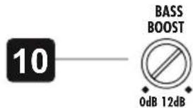
VARIABLE BASS BOOST
By using the BASS BOOST controller [10] you are able to increase the bass enhancement from 0 to 12 dB. ATTENTION: Use the BASS BOOST wisely!
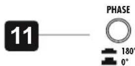
PHASE SWITCH
The PHASE switch [11] allows to switch the phase from 0^ to 180^ to match the output signal with the vehicle's interior acoustic.
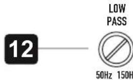
VARIABLE LOW PASS FILTER
Set the desired crossover frequency by using the controller LOW PASS [12]. Thus to that only the frequencies below the chosen crossover frequency will be amplified and the subwoofer plays more precisely and efficient.
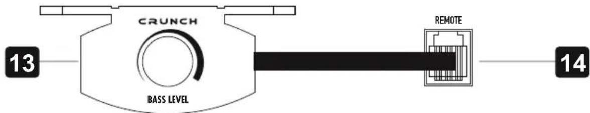
With the included bass level cable remote controller [13] allows to adjust the bass level e.g. out of the driver's seat. Connect the remote controller and the REMOTE terminal [14] with the enclosed cable.
PROTECTION CIRCUIT
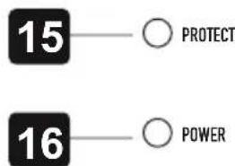
The PROTECT LED [15] lights up red, when the amplifier is overheated, or a short circuit occurs respective a too low impedance load is connected to the speaker outputs. If this events, the internal built-in protection circuit shuts down the amplifier automatically. The amplifier should work again properly after you have solved the problems.
The POWER LED [16] lights up green, if the amplifier is in operation.
ENTRÉE HAUT NIVEAU
flowchart
graph LR
    A["6"] --> B["LOW LEVEL INPUT"]
    B --> C["R"]
    B --> D["L"]
INGRESSO ALTO LIVELLO
CONTROLLO REMOTO DAL LIVELLO DEI BASSI
ENTRADAS DE ALTO NIVEL
©2019 Audio Design GmbH, All Rights Reserved


- GP600
- ACTIVE SUBWOOFER SYSTEM
- INHALTSVERZEICHNIS TABLE OF CONTENT TABLE DES MATIÈRES SOMMARIO INDICE
- HOCHPEGELEINGÄNGE
- AUTOMATISCHE EINSCHALTFUNKTION
- IMPORTANT NOTES PRIOR TO INSTALLATION
- POWER SUPPLY AND TURN-ON-CONNECTION
- AUDIO SIGNAL CABLES
- HIGH LEVEL INPUTS & AUTO TURN ON
- AUTO TURN ON
- INPUT SENSITIVITY
- VARIABLE BASS BOOST
- PHASE SWITCH
- VARIABLE LOW PASS FILTER
- PROTECTION CIRCUIT
- ENTRÉE HAUT NIVEAU
- INGRESSO ALTO LIVELLO
- CONTROLLO REMOTO DAL LIVELLO DEI BASSI
- ENTRADAS DE ALTO NIVEL
Brand : Crunch
Model : GP600
Category : Subwoofer