
GTi800A - Subwoofer Crunch - Free user manual and instructions
Find the device manual for free GTi800A Crunch in PDF.


| Product Type | Car Audio Subwoofer |
| Brand | Crunch |
| Model | GTi800A |
| Size | 8 inches |
| Peak Power Handling | 800 Watts |
| RMS Power Handling | 300 Watts |
| Impedance | 4 Ohms |
| Sensitivity | 87 dB |
| Frequency Response | 30 Hz - 500 Hz |
| Cone Material | Polypropylene with Rubber Surround |
| Mounting Depth | 4.5 inches (114 mm) |
| Mounting Cutout Diameter | 7.2 inches (183 mm) |
| Overall Diameter | 8.6 inches (218 mm) |
| Net Weight | 5.5 lbs (2.5 kg) |
| Recommended Enclosure Type | Sealed or Ported |
| Recommended Sealed Box Volume | 0.5 - 0.8 cubic feet |
| Recommended Ported Box Volume | 1.0 - 1.5 cubic feet |
| Maintenance | Wipe with dry cloth; avoid moisture |
| Safety | Keep away from water; use proper amplifier |
| Spare Parts & Repairability | Contact authorized service centers |
Frequently Asked Questions - GTi800A Crunch
User questions about GTi800A Crunch
0 question about this device. Answer the ones you know or ask your own.
Ask a new question about this device
Download the instructions for your Subwoofer in PDF format for free! Find your manual GTi800A - Crunch and take your electronic device back in hand. On this page are published all the documents necessary for the use of your device. GTi800A by Crunch.
USER MANUAL GTi800A Crunch
natural_image
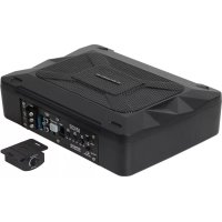
Black industrial device with GTI branding and speaker grille (no readable text beyond branding)GTi800A
ACTIVE SUBWOOFER SYSTEM
BENUTZERHANDBUCH
OWNER'S MANUAL
VERS.1.1
GTI800A
| Output Power RMS | 1 x 200 W |
| Output Power Max. | 1 x 400 W |
| Low Pass Filter | 30 – 250 Hz @ 12 dB/Octave |
| Bass Boost | 0 – 12 dB @ 55 Hz |
| Operating Voltage | +12 V (9 – 15 V), negative ground |
| Low Level Input | RCA |
| High Level Input | yes |
| Auto-Turn-On Function | yes, only over High Level Input |
| Fuse Rating | 15 A |
| Dimensions (B x H x L) | 38,5 x 26,5 x 30/26 cm |
All Specifications are subject to change
ENG
SAFETY INSTRUCTIONS
THE PURCHASED DEVICE IS ONLY SUITABLE FOR AN OPERATION WITH A 12V ON-BOARD ELECTRICAL SYSTEM OF A VEHICLE. Otherwise fire hazard, risk of injury and electric shock consists.
PLEASE DO NOT MAKE ANY OPERATION OF THE SOUND SYSTEM, WHICH DISTRACT YOU FROM A SAFE DRIVING. Do not make any procedures, which demand a longer attention. Perform these operations not until you have stopped the vehicle on a safe place. Otherwise the risk of accident consists.
ADJUST THE SOUND VOLUME TO AN APPROPRIATE LEVEL, THAT YOU ARE STILL ABLE TO HEAR EXTERIOR NOISES WHILE DRIVING. High performance sound systems in vehicles may generate the acoustic pressure of a live concert. The permanent listening to extreme loud music may cause the loss of your hearing abilities. The hearing of extreme loud music while driving may derogate your cognition of warning signals in the traffic. In the interests of the common safeness, we suggest to drive with a lower sound volume. Otherwise the risk of accident consists.
DO NOT COVER COOLING VENTS AND HEAT SINKS. Otherwise this may cause heat accumulation in the device and fire hazard consists.
DO NOT OPEN THE DEVICE. Otherwise fire hazard, risk of injury and electric shock consists. Also this may cause a loss of the warranty.
REPLACE FUSES ONLY WITH FUSE WITH THE SAME RATING. Otherwise fire hazard and risk of electric shock consists.
DO NOT USE THE DEVICE ANY LONGER, IF A MAL-FUNCTION, WHICH REMAINS UNREMEDIED. Refer in this case to the chapter TROUBLE SHOOTING. Otherwise risk of injury and the damage of the device consists. Commit the device to an authorized retailer.
INTERCONNECTION AND INSTALLATION SHOULD BE ACCOMPLISHED BY SKILLED STAFF ONLY. The interconnection and installation of this device demands technical aptitude and experience. For your own safeness, commit the interconnection and installation to your car audio retailer, where you have purchased the device.
DISCONNECT THE GROUND CONNECTION FROM THE VEHICLE'S BATTERY BEFORE INSTALLATION. Before you start with the installation of the sound system, disconnect by any means the ground supply wire from the battery, to avoid any risk of electric shock and short circuits.
CHOOSE AN APPROPRIATE LOCATION FOR THE INSTALLATION OF THE DEVICE. Look for an appropriate location for the device, which ensures a sufficient air circulation. The best places are spare wheel cavities, and open spaces in the trunk area. Less suitable are storage spaces behind the side coverings or under the car seats.
DO NOT INSTALL THE DEVICE AT LOCATIONS, WHERE IT WILL BE EXPOSED TO HIGH HUMIDITY AND DUST. Install the device at a location, where it will be protected from high humidity and dust. If humidity and dust attain inside the device, malfunctions may be caused.
MOUNT THE DEVICE AND OTHER COMPONENTS OF THE SOUND SYSTEM SUFFICIENTLY. Otherwise the device and components may get loose and act as dangerous objects, which could cause serious harm and damages in the passenger room.
ENSURE NOT TO DAMAGE COMPONENTS, WIRES AND CABLES OF THE VEHICLE WHEN YOU DRILL THE MOUNTING HOLES. If you drill the mounting holes for the installation into the vehicle's chassis, ensure by any means, not to damage, block or tangent the fuel pipe, the gas tank, other wires or electrical cables.
ENSURE CORRECT CONNECTION OF ALL TERMINALS. Faulty connections may could cause fire hazard and lead to damages of the device.
DO NOT INSTALL AUDIO CABLES AND POWER SUPPLY WIRES TOGETHER. Ensure while installation not to lead the audio cables between the head unit and the amplifier together with the power supply wires on the same side of the vehicle. The best is a areal separated installation in the left and right cable channel of the vehicle. Therewith a overlap of interferences on the audio signal will be avoided. This stands also for the equipped bass-remote wire, which should be installed not together with the power supply wires, but rather with the audio signal cables.
ENSURE THAT CABLES MAY NOT CAUGHT UP IN CLOSE-BY OBJECTS. Install all the wires and cables like described on the following pages, therewith these may not hinder the driver. Cables and wires which are installed close-by the steering wheel, gear lever or the brake pedal, may caught up and cause highly dangerous situations.
DO NOT SPLICE ELECTRICAL WIRES. The electrical wires should not be bared, to provide power supply to other devices. Otherwise the load capacity of the wire may get overloaded. Use therefor a appropriate distribution block. Otherwise fire hazard and risk of electric shock consists.
DO NOT USE BOLTS AND SCREW NUTS OF THE BRAKE SYSTEM AS GROUND POINT. Never use for the installation or the ground point bolts and screw-nuts of the brake system, steering system or other security-relevant components. Otherwise fire hazard consists or the driving safety will be derogated.
ENSURE NOT TO BEND OR SQUEEZE CABLES AND WIRES BY SHARP OBJECTS. Do not install cables and wires not close-by movable objects like the seat rail or may be bended or harmed by sharp and barbed edges. If you lead a wire or cable through the hole in a metal sheet, protect the insulation with a rubber grommet.
KEEP AWAY SMALL PARTS AND JACKS FROM CHILDREN. If objects like these will be swallowed, the risk of serious injuries consists. Consult promptly a medical doctor, if a child swallowed a small object.
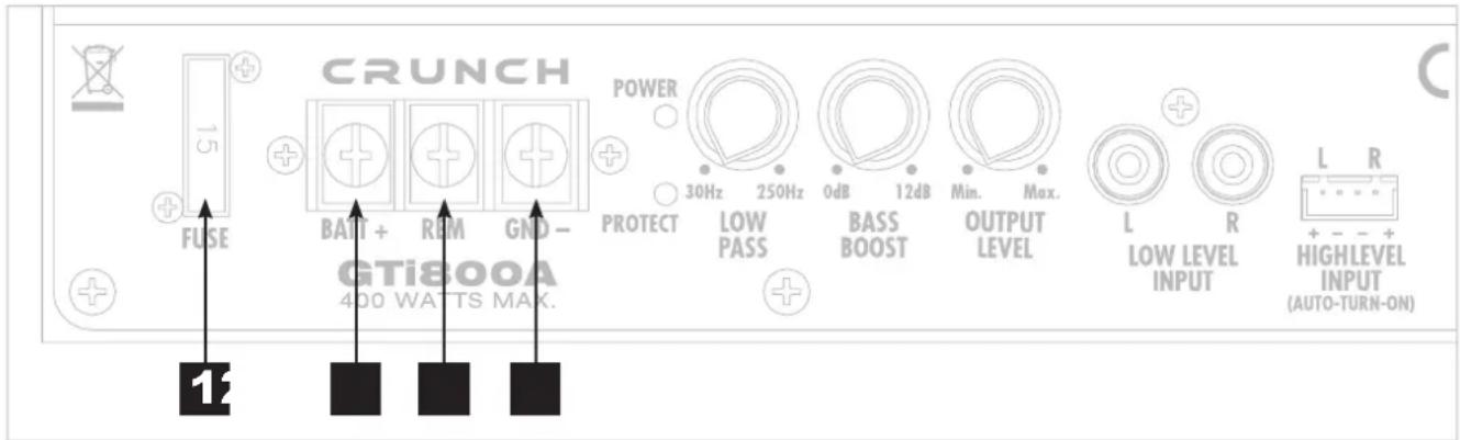
BEFORE THE INTERCONNECTION
For the professional installation of a sound system appropriate wiring kits are available in car audio retailer stores. Ensure a sufficient profile section (at least 10 mm ^2 ), a suitable fuse rating and a high conductivity of the cables when you purchase your wiring kit. Clean and remove rust-streaked and oxidized areas on the contact points of the battery and the ground connection. Make sure that all screws are fixed tight after the installation, because loosely connections may cause malfunctions, insufficient power supply or interferences. We recommend therefore the RENEGADE REN10KIT wire kit.

FUSE
The inserted fuse protects the device against short circuits and overload. The standard fuse rating of 15 A must be strictly adhered, when you replace a defective fuse.

BATT+
Connect the BATT+12V-terminal with the +12V pole of the vehicle's battery. Use a suitable cable with a sufficient cross section (at least 10 mm^2 ) and install an additional in-line fuse. For safety reasons the distance between the fuse block and the battery should be shorter than 30 cm. Do not set in the fuse into the fuse block until the installation is accomplished.

REM (TURN-ON SIGNAL)
Connect the turn-on signal (e.g. automatic antenna) or the turn-on remote wire of your head unit with the REM-terminal of the sound system. Use a suitable cable with a sufficient cross section (0,5 mm^2) . Thereby the sound system will turn on or off automatically with your head unit. If your head unit is not equipped with a remote wire, refer to page 10, section #6. If you use the HIGH LEVEL INPUT like described there, you must not connect the turn-on signal under REM.

GND
Connect this GROUND terminal with a suitable contact ground point on the vehicle's chassis. The ground wire must be as short as possible and must be connected to a blank metallic point at the vehicle's chassis. Ensure that this ground point has a stable and safe electric connection to the negative “-”pole of the battery. Check this ground wire from the battery to the ground point if possible and enforce it, if required. Use a ground wire with a sufficient cross section (at least 10 mm ^2 ) and the same size like the plus (+12V) power supply wire.

NOTE
Before you start with the installation of the sound system, disconnect necessarily the GROUND connection wire from the battery to avoid any risk of electric shocks and short circuits.
ENG
FUNCTIONS AND OPERATIONAL CONTROLS
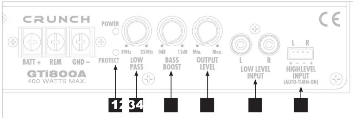
POWER/PROTECT LED
The POWER LED lights up when the sound system is turned-on and ready for operation. The PROTECT LED lights up, if a malfunction has occurred on the device. Please refer to the notes in the TROUBLESHOOTING section.
LOW PASS
The LOW PASS controller adjusts the cut-off point of the frequency range to above. This means all mids and highs will be eliminated in the audio signal. The cut-off frequency is continuously adjustable from 30 Hz to 250 Hz.
BASS BOOST
By using the BASS BOOST controller, you are able to increase the bass boost level from 0 dB to 12 dB.
Caution: Please use the bass boost with care.
OUTPUT LEVEL
The OUTPUT LEVEL controller adjusts the output level and allows to match the subwoofer level with the head unit.
LOW LEVEL INPUT
The LOW LEVEL INPUT RCA jacks must be connected with the RCA output jacks of the head unit. This input is only suited for low level signals.
HIGH LEVEL INPUT (AUTO-TURN-ON)
The HIGH LEVEL INPUT is suitable to connect the speaker outputs of the head unit, if no pre-amplifier RCA outputs are available. Please use the enclosed wire harness for the connection. Please observe and ensure the correct polarity of all connections. NEVER use the High Level Input and the RCA inputs at the same time. This may damage the sound system seriously.
AUTO-TURN-ON: If your head unit does not have a remote turn-on cable (REMOTE, see page 9, section # 3), you must use the input HIGH LEVEL INPUT. This automatically turns the sound system on or off when the head unit is switched on.

NOTE
Always ensure the correct polarity of all connections. The interchange of plus and minus cause total loss of bass playback and could damage the speakers.
TROUBLE SHOOTING
ENG
If you are having problems after installation follow the procedures below.
Procedure 1:
Check the device for proper connections.
Verify that POWER LED is on. If POWER LED is on skip to procedure 3, if not continue.
- Check the fuse of the device or the external fuse on battery positive cable. Replace if necessary.
- Verify that Ground connection is connected to clean metal on the vehicle's chassis. Repair/replace if necessary.
- Verify there is 9 to 16 Volts present at the positive battery and remote turn-on cable. Verify quality connections for both cables at device, head unit and battery/fuse holder. Repair/replace if necessary.
Procedure 2:
PROTECT LED is on.
- If the PROTECT LED is on, this is a sign of driving the device at very high power levels without adequate airflow around the device. Shut off the system and allow device to cool down. Check that the vehicle charging system is maintaining proper voltage. If the previous items do not solve the problem, a fault may be in the device.
Procedure 3:
Check the device for a proper audio signal.
- Verify good RCA input connections at head unit and device. Check entire length of cables for kinks, splices, etc. Test RCA inputs for AC volts with stereo on. Repair/replace if necessary.
Procedure 4:
Check the device for a popping noise while turning on.
-
Disconnect input signal to device and turn device on and off.
-
If the noise is eliminated, connect the REMOTE lead of device to source unit with a delay turn-on module.
Procedure 5:
Check the device if you experience excess Engine Noise.
- Route all signal carrying wires (RCA, Speaker cables) away from power and ground wires.
OR
- Bypass any and all electrical components between the head unit and the device. Connect unit directly to input of the device. If noise goes away the unit being bypassed is the cause of the noise.
OR
- Remove existing ground wires for all electrical components. Reground wires to different locations. Verify that grounding location is clean, shiny metal free of paint, rust etc.
OR
- Have alternator and battery load tested by your mechanic. Verify good working order of vehicle electrical system including distributor, spark plugs, spark plug wires, voltage regulator etc.
GTICRUNCH

Audio Design GmbH
Am Breilingsweg 3 · D-76709 Kronau/Germany
Tel. +49 7253 - 9465-0 · Fax +49 7253 - 946510
www.audiodesign.de
© Audio Design GmbH, All Rights Reserved




- GTi800A
- ACTIVE SUBWOOFER SYSTEM
- ENG
- SAFETY INSTRUCTIONS
- BEFORE THE INTERCONNECTION
- FUSE
- BATT+
- REM (TURN-ON SIGNAL)
- GND
- NOTE
- FUNCTIONS AND OPERATIONAL CONTROLS
- POWER/PROTECT LED
- LOW PASS
- BASS BOOST
- OUTPUT LEVEL
- LOW LEVEL INPUT
- HIGH LEVEL INPUT (AUTO-TURN-ON)
- TROUBLE SHOOTING
- Procedure 1:
- Procedure 2:
- Procedure 3:
- Procedure 4:
- Procedure 5:
- GTICRUNCH
Brand : Crunch
Model : GTi800A
Category : Subwoofer