
DLM5200N - Sewing machine JUKI - Free user manual and instructions
Find the device manual for free DLM5200N JUKI in PDF.

User questions about DLM5200N JUKI
0 question about this device. Answer the ones you know or ask your own.
Ask a new question about this device
Download the instructions for your Sewing machine in PDF format for free! Find your manual DLM5200N - JUKI and take your electronic device back in hand. On this page are published all the documents necessary for the use of your device. DLM5200N by JUKI.
USER MANUAL DLM5200N JUKI
natural_image
Line drawing of a JUKI sewing machine (no text or symbols on the device body)| NOTE : Read safety instructions carefully and understand them before using.Retain this Instruction Manual for future reference. |
| HINWEIS : Lesen Sie die Sicherheitsanweisungen aufmerksam durch, um sich mit ihnen vertraut zu machen, bevor Sie diese Maschine in Betrieb nehmen. Bewahren Sie diese Bedienungsanleitung für spätere Bezugnahme auf. |
| NOTE : Avant d’utiliser la machine, lire attentivement toutes les consignes de sécurité.Conserver ce manuel pour pouvior le consulter en cas de besoin. |
| NOTA : Antes de comenzar a usar esta máquina lea con detención hasta comprender todas las instrucciones de seguridad. Conserve este Manual de instrucciones a mano para futuras consultas. |
| NOTA : Leggere attentamente e compredere tutte le istruzioni per la sicurezza prima di inziare l’ uso di questa macchina. Conservare questo Manuale d’Instruzioni per pronto riferimento. |
TO ENSURE SAFE USE OF YOUR SEWING MACHINE
For the sewing machine, automatic machine and ancillary devices (hereinafter collectively referred to as "machine"), it is inevitable to conduct sewing work near moving parts of the machine. This means that there is always a possibility of unintentionally coming in contact with the moving parts. Operators who actually operate the machine and maintenance personnel who are involved in maintenance and repair of the machine are strongly recommended to carefully read to fully understand the following SAFETY PRECAUTIONS before using/maintaining the machine. The content of the SAFETY PRECAUTIONS includes items which are not contained in the specifications of your product.
The risk indications are classified into the following three different categories to help understand the meaning of the labels. Be sure to fully understand the following description and strictly observe the instructions.
( I ) Explanation of risk levels

DANGER :
This indication is given where there is an immediate danger of death or serous injury if the person in charge or any third party mishandles the machine or does not avoid the dangerous situation when operating or maintaining the machine.

WARNING :
This indication is given where there is a potentiality for death or serious injury if the person in charge or any third party mishandles the machine or does not avoid the dangerous situation when operating or maintaining the machine.

CAUTION :
This indication is given where there is a danger of medium to minor injury if the person in charge or any third party mishandles the machine or does not avoid the dangerous situation when operating or maintaining the machine.

Items requiring special attention.
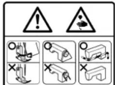
(II) Explanation of pictorial warning indications and warning labels
| Pictorial warning indication |  | There is a risk of injury if contact-ing a moving section. | Pictorial warning indication |  | Be aware that holding the sewing machine during operation can hurt your hands. | |
 | There is a risk of electrical shock if contacting a high-voltage section. |  | There is a risk of entanglement in the belt resulting in injury. | |||
 | There is a risk of a burn if contact-ing a high-temperature section. |  | There is a risk of injury if you touch the button carrier. | |||
 | Be aware that eye deficiency can be caused by looking directly at the laser beam. | Indication label |  | The correct direction is indicated. | ||
 | There is a risk of contact between your head and the sewing ma-chine. |  | Connection of a earth cable is indicated. | |||
text_image
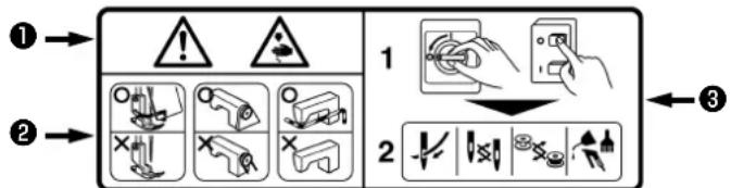
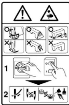
Diagram illustrating safety warning and tool application steps with labeled icons and numbered instructions- There is the possibility that slight to serious injury or death may be caused.
- There is the possibility that injury may be caused by touching moving part.
② • To perform sewing work with safety guard.
• To perform sewing work with safety cover. - To perform sewing work with safety protection device.
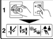
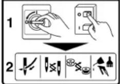
③ • Be sure to turn the power OFF before carrying out "machine-head threading", "needle changing", "bobbin changing" or "oiling and cleaning".


Hazardous voltage will cause injury.
Turn off main switch and unplug power cord and wait at least 5 minutes before opening this cover.
text_image
1 2


DANGER
- When it is necessary to open the control box containing electrical parts, be sure to turn the power off and wait for five minutes or more before opening the cover in order to prevent accident leading to electrical shock.

CAUTION
Basic precaution
- Be sure to read the instruction manual and other explanatory documents supplied with accessories of the machine before using the machine. Carefully keep the instruction manual and the explanatory documents at hand for quick reference.
- The content of this section includes items which are not contained in the specifications of your product.
- Be sure to wear safety goggles to protect against accident caused by needle breakage.
- Those who use a heart pacer have to use the machine after consultation with a medical specialist.
Safety devices and warning labels
- Be sure to operate the machine after verifying that safety device(s) is correctly installed in place and works normally in order to prevent accident caused by lack of the device(s).
- If any of the safety devices is removed, be sure to replace it and verify that it works normally in order to prevent accident that can result in personal injury or death.
- Be sure to keep the warning labels adhered on the machine clearly visible in order to prevent accident that can result in personal injury or death. If any of the labels has stained or come unstuck, be sure to change it with a new one.
Application and modification
- Never use the machine for any application other than its intended one and in any manner other than that prescribed in the instruction manual in order to prevent accident that can result in personal injury or death. JUKI assumes no responsibility for damages or personal injury or death resulting from the use of the machine for any application other than the intended one.
- Never modify and alter the machine in order to prevent accident that can result in personal injury or death. JUKI assumes no responsibility for damages or personal injury or death resulting from the machine which has been modified or altered.
Education and training
- In order to prevent accident resulting from unfamiliarity with the machine, the machine has to be used only by the operator who has been trained/educated by the employer with respect to the machine operation and how to operate the machine with safety to acquire adequate knowledge and operation skill. To ensure the above, the employer has to establish an education/training plan for the operators and educate/train them beforehand.
Items for which the power to the machine has to be turned off
Turning the power off: Turning the power switch off, then removing the power plug from the outlet. This applies to the following.
- Be sure to immediately turn the power off if any abnormality or failure is found or in the case of power failure in order to protect against accident that can result in personal injury or death.
- To protect against accident resulting from abrupt start of the machine, be sure to carry out the following operations after turning the power off. For the machine incorporating a clutch motor, in particular, be sure to carry out the following operations after turning the power off and verifying that the machine stops completely.
2-1. For example, threading the parts such as the needle, looper, spreader etc. which have to be threaded, or changing the bobbin.
2-2. For example, changing or adjusting all component parts of the machine.
2-3. For example, when inspecting, repairing or cleaning the machine or leaving the machine. - Be sure to remove the power plug by holding the plug section instead of the cord section in order to prevent electrical-shock, earth-leakage or fire accident.
- Be sure to turn the power off whenever the machine is left unattended between works.
- Be sure to turn the power off in the case of power failure in order to prevent accident resulting of breakage of electrical components.
PRECAUTIONS TO BE TAKEN IN VARIOUS OPERATION STAGES
Transportation
- Be sure to lift and move the machine in a safe manner taking the machine weight in consideration. Refer to the text of the instruction manual for the mass of the machine.
- Be sure to take sufficient safety measures to prevent falling or dropping before lifting or moving the machine in order to protect against accident that can result in personal injury or death.
- Once the machine has been unpacked, never re-pack it for transportation to protect the machine against breakage resulting from unexpected accident or dropping.
Unpacking
- Be sure to unpack the machine in the prescribed order in order to prevent accident that can result in personal injury or death. In the case the machine is crated, in particular, be sure to carefully check nails. The nails have to be removed.
- Be sure to check the machine for the position of its center of gravity and take it out from the package carefully in order to prevent accident that can result in personal injury or death.
Installation
(I) Table and table stand
- Be sure to use JUKI genuine table and table stand in order to prevent accident that can result in personal injury or death. If it is inevitable to use a table and table stand which are not JUKI genuine ones, select the table and table stand which are able to support the machine weight and reaction force during operation.
- If casters are fitted to the table stand, be sure to use the casters with a locking mechanism and lock them to secure the machine during the operation, maintenance, inspection and repair in order to prevent accident that can result in personal injury or death.
(II) Cable and wiring
- Be sure to prevent an extra force from being applied to the cable during the use in order to prevent electrical-shock, earth-leakage or fire accident. In addition, if it is necessary to cable near the operating section such as the V-belt, be sure to provide a space of 30 mm or more between the operating section and the cable.
- Be sure to avoid starburst connection in order to prevent electrical-shock, earth-leakage or fire accident.
- Be sure to securely connect the connectors in order to prevent electrical-shock, earth-leakage or fire accident. In addition, be sure to remove the connector while holding its connector section.
(III) Grounding
- Be sure to have an electrical expert install an appropriate power plug in order to prevent accident caused by earth-leakage or dielectric strength voltage fault. In addition, be sure to connect the power plug to the grounded outlet without exceptions.
- Be sure to ground the earth cable in order to prevent accident caused by earth leakage.
(IV) Motor
- Be sure to use the specified rated motor (JUKI genuine product) in order to prevent accident caused by burnout.
- If a commercially available clutch motor is used with the machine, be sure to select one with an entanglement preventive pulley cover in order to protect against being entangled by the V-belt.
Before operation
- Be sure to make sure that the connectors and cables are free from damage, dropout and looseness before turning the power on in order to prevent accident resulting in personal injury or death.
- Never put your hand into the moving sections of the machine in order to prevent accident that can result in personal injury or death. In addition, check to be sure that the direction of rotation of the pulley agrees with the arrow shown on pulley.
- If the table stand with casters is used, be sure to secure the table stand by locking the casters or with adjusters, if provided, in order to protect against accident caused by abrupt start of the machine.
During operation
- Be sure not to put your fingers, hair or clothing close to the moving sections such as the handwheel, hand pulley and motor or place something near those sections while the machine is in operation in order to prevent accident caused by entanglement that can result in personal injury or death.
- Be sure not to place your fingers near the surround area of the needle or inside the thread take-up lever cover when turning the power on or while the machine is in operation in order to prevent accident that can result in personal injury or death.
- The machine runs at a high speed. Never bring your hands near the moving sections such as looper, spreader, needle bar, hook and cloth trimming knife during operation in order to protect your hands against injury. In addition, be sure to turn the power off and check to be sure that the machine completely stops before changing the thread.
-
Be careful not to allow your fingers or any other parts of your body to be caught between the machine and table when removing the machine from or replacing it on the table in order to prevent accident that can result in personal injury or death.
-
Be sure to turn the power off and check to be sure that the machine and motor completely stop before removing the belt cover and V-belt in order to prevent accident caused by abrupt start of the machine or motor.
- If a servomotor is used with the machine, the motor does not produce noise while the machine is at rest. Be sure not to forget to turn the power off in order to prevent accident caused by abrupt start of the motor.
- Never use the machine with the cooling opening of the motor power box shielded in order to prevent fire accident by overheat.
Lubrication
- Be sure to use JUKI genuine oil and JUKI genuine grease to the parts to be lubricated.
- If the oil adheres on your eye or body, be sure to immediately wash it off in order to prevent inflammation or irritation.
- If the oil is swallowed unintentionally, be sure to immediately consult a medical doctor in order to prevent diarrhea or vomiting.
Maintenance
- In prevention of accident caused by unfamiliarity with the machine, repair and adjustment has to be carried out by a service technician who is thoroughly familiar with the machine within the scope defined in the instruction manual. Be sure to use JUKI genuine parts when replacing any of the machine parts. JUKI assumes no responsibility for any accident caused by improper repair or adjustment or the use of any part other than JUKI genuine one.
- In prevention of accident caused by unfamiliarity with the machine or electrical-shock accident, be sure to ask an electrical technician of your company or JUKI or distributor in your area for repair and maintenance (including wiring) of electrical components.
- When carrying out repair or maintenance of the machine which uses air-driven parts such as an air cylinder, be sure to remove the air supply pipe to expel air remaining in the machine beforehand, in order to prevent accident caused by abrupt start of the air-driven parts.
- Be sure to check that screws and nuts are free from looseness after completion of repair, adjustment and part replacement.
- Be sure to periodically clean up the machine during its duration of use. Be sure to turn the power off and verify that the machine and motor stop completely before cleaning the machine in order to prevent accident caused by abrupt start of the machine or motor.
- Be sure to turn the power off and verify that the machine and motor stop completely before carrying out maintenance, inspection or repair of the machine. (For the machine with a clutch motor, the motor will keep running for a while by inertia even after turning the power off. So, be careful.)
- If the machine cannot be normally operated after repair or adjustment, immediately stop operation and contact JUKI or the distributor in your area for repair in order to prevent accident that can result in personal injury or death.
- If the fuse has blown, be sure to turn the power off and eliminate the cause of blowing of the fuse and replace the blown fuse with a new one in order to prevent accident that can result in personal injury or death.
- Be sure to periodically clean up the air vent of the fan and inspect the area around the wiring in order to prevent fire accident of the motor.
Operating environment
- Be sure to use the machine under the environment which is not affected by strong noise source (electromagnetic waves) such as a high-frequency welder in order to prevent accident caused by malfunction of the machine.
- Never operate the machine in any place where the voltage fluctuates by more than "rated voltage ± 10% in order to prevent accident caused by malfunction of the machine.
- Be sure to verify that the air-driven device such as an air cylinder operates at the specified air pressure before using it in order to prevent accident caused by malfunction of the machine.
- To use the machine with safety, be sure to use it under the environment which satisfies the following conditions:
Ambient temperature during operation 5°C to 35°C
Relative humidity during operation 35% to 85%
- Dew condensation can occur if bringing the machine suddenly from a cold environment to a warm one. So, be sure to turn the power on after having waited for a sufficient period of time until there is no sign of water droplet in order to prevent accident caused by breakage or malfunction of the electrical components.
- Be sure to stop operation when lightning flashes for the sake of safety and remove the power plug in order to prevent accident caused by breakage or malfunction of the electrical components.
- Depending on the radio wave signal condition, the machine may generate noise in the TV or radio. If this occurs, use the TV or radio with kept well away from the machine.
- In order to ensure the work environment, local laws and regulations in the country where the sewing machine is installed shall be followed. In the case the noise control is necessary, an ear protector or other protective gear should be worn according to the applicable laws and regulations.
- Disposal of products and packages and treatment of used lubricating oil should be carried out properly according to the relevant laws of the country in which the sewing machine is used.
Precautions to be taken so as to use the DLM-5200N and DLM-5400N-7 more safely
| 1. To avoid electrical shock hazards, neither open the cover of the electrical box for the motor nor touch the components mounted inside the electrical box. | |
| 1. To avoid personal injury, never operate the machine with any of the belt cover, fi nger guard or safety devices removed.2. To prevent possible personal injuries caused by being caught in the machine, keep your fingers, head and clothes away from the handwheel, V belt and the motor while the machine is operation. In addition, place nothing around them.3. To avoid personal injury, never put your hand under the needle when you turn “ON” the power switch or operate the machine.4. To avoid personal injury, never put your fingers into the thread take-up cover while the machine is in operation.5. The hook rotates at a high speed while the machine is in operation. To prevent possible injury to hands, be sure to keep your hands away from the vicinity of the hook during operation. In addition, be sure to turn OFF the power to the machine when replacing the bobbin.6. To avoid possible personal injuries, be careful not to allow your fingers in the machine when tiling/raising the machine head.7. To avoid possible accidents because of abrupt start of the machine, turn OFF the power to the machine when tilting the machine head or removing the belt cover and the V belt.8. If your machine is equipped with a servo-motor, the motor does not produce noise while the machine is at rest. To avoid possible accidents due to abrupt start of the machine, be sure to turn OFF the power to the machine.9. To avoid electrical shock hazards, never operate the sewing machine with the ground wire for the power supply removed.10. To prevent possible accidents because of electric shock or damaged electrical component(s), turn OFF the power switch in prior to the connection/disconnection of the power plug.11. Be careful of handling this product so as not to pour water or oil, shock by dropping, and the like since this product is a precision instrument. |

CAUTION
In addition, be aware that the safety devices such as the "eye protection cover" and "finger guard" are sometimes omitted in the sketches, illustrations and figures included in the Instruction Manual for the explanation's sake. In the practical use, never remove those safety devices.
DECLARATION OF INCORPORATION OF PARTLY COMPLETED MACHINERY
We hereby declare that the sewing machine (sewing head) described below ;
- Must not be put into service until the machinery to which it is incorporated has been declared in conformity with the provisions of the Directive 2006/42/EC, and
- Conforms to the essential requirements of the Directive 2006/42/EC, described in the technical documentation, and
- To be prepared with the above technical documentation compiled in accordance with part B of Annex VII, and
- Also to conform to the RoHS Directive 2011/65/EU
- Relevant information on which should be transmitted in response to a reasoned request by the national authorities, by the electronic method or other according to the request.
Model DLM-5200N, DLM-5400N-7
Description Industrial Sewing Machine
Function make stitches and sew
Applied harmonized standards, in particular :
EN ISO12100, EN ISO10821, EN 50581
Manufacturer :
JUKI CORPORATION
2-11-1, Tsurumaki, Tama-shi, Tokyo, Japan
text_image
Warning symbols and safety icons for mechanical devices, including warning signs and hazard symbols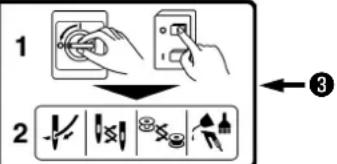
text_image
1 2 3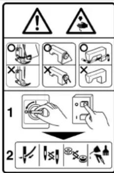
text_image
1 2


Hazardous voltage will cause injury.
Turn off main switch and unplug power cord and wait at least 5 minutes before opening this cover.

GEFAHR
text_image
Warning symbols and safety icons for mechanical devices, including warning signs and hazard symbols
text_image
1 2 3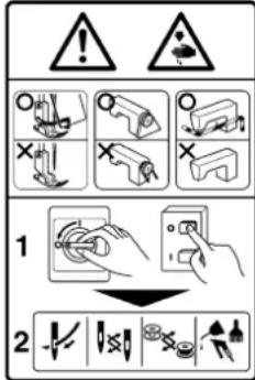
text_image
1 2


text_image
Warning symbols with icons and labels, including exclamation marks and safety symbols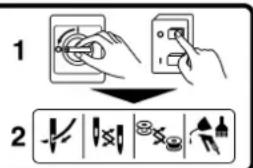
text_image
1 2
text_image
Warning symbols and safety icons for electrical hazard, including warning signs, hazard symbols, and various mechanical or electrical hazard symbols.

To avoid malfunction and damage of the machine, confirm the following.

- Before you put the machine into operation for the first time after the set-up, clean it thoroughly. Remove all dust gathering during transportation and oil it well.
- Confirm that the voltage has been correctly set. Confirm that the power plug has been properly connected to the power supply.
- Never use the machine in the state where the voltage type is different from the designated one.
- Confirm that the direction of rotation of the motor pulley is correct.
- Operate your machine at the normat sewing speed or less for the first month after the set-up.

| DLM-5200N DLM-5400N-7 | ||
| Application | Light-weight materials and medium-heavy weight materials | General fabrics and medium-heavy weight materials |
| Sewing speed Max. 4,500 sti/min | ||
| Stitch length 5 mm 4 mm | ||
| Presser foot lift (by kenn lifter) | 10 mm (standard) 13 mm (max.) | |
| Needle | SCHMETZ 134 #65 to #100(DBx1 #9 to #16) | SCHMETZ 134 #65 to #100 (standard #90)(DBx1 #9 to #16 (standard #14)) |
| Stroke of the cloth cuttin knife | 5 mm | |
| Lubricating oil JUKI New Defrix Oil No.1 | ||
| Noise | DLM-5200N- Equivalent continuous emission sound pressure level (LpA) at the workstation:A-weighted value of 81.0 dB; (Includes KpA= 2.5 dB); according to ISO 10821- C.6.2 -ISO 11204 GR2 at 4,000 sti/min.- Sound power level (LWA);A-weighted value of 88.0 dB; (Includes KWA= 2.5 dB); according to ISO 10821- C.6.2 -ISO 3744 GR2 at 4,000 sti/min.DLM-5400N-7- Equivalent continuous emission sound pressure level (LpA) at the workstation:A-weighted value of 81.5 dB; (Includes KpA= 2.5 dB); according to ISO 10821- C.6.2 -ISO 11204 GR2 at 4,500 sti/min.- Sound power level (LWA);A-weighted value of 86.5 dB; (Includes KWA= 2.5 dB); according to ISO 10821- C.6.2 -ISO 3744 GR2 at 4,500 sti/min. | |
- TECHNISCHE DATEN
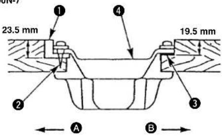
1) The oil pan should be installed in such a way that it is securely held in position by the four corners of the machine table groove. 2) Fix two rubber seats ① on side A (operator's side) using nail ② as illustrated above. Fix two cushion seats ③ on side B (hinged side) using a rubber-based adhesive.
Then place oil pan ④ on the fixed seats.
DLM-5400N-7
text_image
23.5 mm 19.5 mm ① ② ③ A BDLM-5200N

text_image
22.5 mm 18.5 mm ① ② ③ A B2. INSTALACION
text_image
Technical diagram of a mechanical component with numbered parts and an inset view labeled A, B, 1, 3, 4.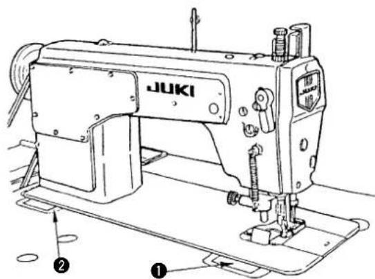
text_image
JUKI ① ②2. INSTALLATION
Carry out the following steps of procedure after the power switch has been turned OFF.

natural_image
Technical line drawing of mechanical components and assembly (no text or symbols)
natural_image
Technical line drawing of a mechanical fixture assembly (no text or symbols)-
INSTALLING THE THREAD STAND
-
AUFSTELLEN DES GARNSTÄNDERS
-
POSE DU BANC DE FIL
-
INSTALACION DEL PEDESTAL DEL HILO
-
MONTAGGIO DEL PORTAFILO

Carry out the following steps of procedure after the power switch has been turned OFF.

1) Fill oil pan will JUKI New Derix Oil No. 1 up to HIGH mark A.
2) When the oil level lowers below LOW mark B, refi II the oil pan with the specified oil.
3) When you operate the machine after lubrication, you will see splashing oil through oil slight window ② if the lubrication is adequate.
(Caution)
- When you first operate your machine after setup or after an extended period of disuse, run your machine at 3,000 sti/min to 3,500 sti/min. for about 10 minutes for the purpose of break-in.
- When the machine is continuously used at a low speed (2,000 sti/min or less), make the machine run idle at a high speed (4,000 sti/min or more) for approximately 5 minutes once a week. Use clean oil and when the oil becomes dirty, replace it with clean oil as soon as possible. When you continue to use the machine with dirty oil, the trouble will be caused.
6. LUBRIFICATION
Carry out the following steps of procedure after the power switch has been turned OFF.

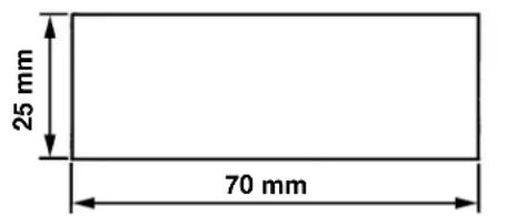
7. ADJUSTING THE AMOUNT OF OIL (OIL SPLASHES)
7. REGLAGE DE LA QUANTITE D'HUILE (PROJECTIONS D'HUILE)
① Amount of oil (oil splashes) confirmation paper Ölmengen-(Ölspritzer)-Prüfpapier
Papier de vérifi cation de la quantité d'huile (projections d'huile) Papel de confi rmación de cantidad de aceite (manchas de aceite) Foglio di carta per il controllo della quantità di olio (spruzzi di olio)
② Position to confirm the amount of oil (oil splashes) Position zur Prüfung der Ölmenge (Ölspritzer)
Position pour la vérification de la quantité d'huile (projections d'huile) Posición para confirmar la cantidad de aceite (manchas de aceite) Posizione per verifi care la quantità di olio (spruzzi di olio)
text_image
25 mm 70 mmOil splashes confi rmation paper Ölspritzer-Prüfpapier
Papier de vérifi cation des projections d'huile Papel de confi rmación de manchas de aceite Carta per verifi care gli spruzzi di olio
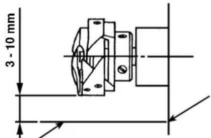
text_image
3 - 10 mm1. Confirmation of the amount of oil in the hook
* When carrying out the procedure described below in 2, remove the slide plate and take extreme caution not to allow your fingers to come in contact with the hook.
1) If the machine has not been sufficiently warmed up for operation, make the machine run idle for approximately three minutes. (Moderate intermittent operation)
2) Place the amount of oil (oil spots) confirmation paper under the hook immediately after the machine stops running.
3) Confirm the height of the oil surface in the oil reservoir is within the range between "HIGH" and "LOW".
4) Confirmation of the amount of oil should be completed in five seconds. (Check the period of time with a watch.)
text_image
Diagram showing a rotating mechanical component with labeled points A and B, indicating rotational motion.2. Adjusting the amount of oil (oil spots) in the hook
1) Turning the oil amount adjustment screw attached on the hook driving shaft front bushing in the “+” direction (in direction A) will increase the amount of oil (oil spots) in the hook, or in the “-” direction (in direction B) will decrease it.
2) After the amount of oil in the hook has been properly adjusted with the oil amount adjustment screw, make the sewing machine run idle for approximately 30 seconds to check the amount of oil in the hook.
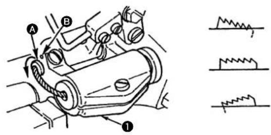
3. Sample showing the appropriate amount of oil in the hook
1) The state given in the figure shows the appropriate amount of oil (oil splashes). It is necessary to finely adjust the amount of oil in accordance with the sewing processes. However, do not excessively increase/decrease the amount of oil in the hook. (If the amount of oil is too small, the hook will be seized (the hook will be hot). If the amount of oil is too much, the sewing product may be stained with oil.)
2) Adjust the amount of oil in the hook so that the oil amount (oil splashes) should not change while checking the oil amount three times (on the three sheets of paper).
natural_image
Technical line drawing of a mechanical assembly with no visible text or symbols4. Confirmation of the amount of oil supplied to the face plate parts
* When carrying out the work described below in 2), remove the face plate and take extreme caution not to allow your fingers to come in contact with the thread take-up lever.
1) If the machine has not been sufficiently warmed up for operation, make the machine run idle for approximately three minutes. (Moderate intermittent operation)
2) Place the amount of oil (oil spots) confirmation paper under the hook immediately after the machine stops running.
3) Confirm the height of the oil surface in the oil reservoir is within the range between "HIGH" and "LOW".
4) The time required for the confirmation of the amount of oil (oil splashes) should be completed in ten seconds. (Measure the period of time with a watch.)
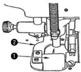
5. Adjusting the amount of oil supplied to the face plate parts
1) Adjust the amount of oil supplied to the thread take-up and needle bar crank ② by turning adjust pin ①.
2) The minimum amount of oil is reached when marker dot A is brought close to needle bar crank ② by turning the adjust pin in direction B.
3) The maximum amount of oil is reached when marker dot A is brought to the position just opposite from the needle bar crank by turning the adjust pin in direction C.
6. Sample showing the appropriate amount of oil supplied to the face plate parts
1) The state given in the figure shows the appropriate amount of oil (oil splashes). It is necessary to finely adjust the amount of oil in accordance with the sewing processes. However, do not excessively increase/decrease the amount of oil in the hook. (If the amount of oil is too small, the hook will be seized (the hook will be hot). If the amount of oil is too much, the sewing product may be stained with oil.)
2) Adjust the amount of oil in the hook so that the oil amount (oil splashes) should not change while checking the oil amount three times (on the three sheets of paper).
natural_image
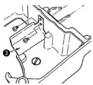
Technical line drawing of a mechanical assembly with no visible text or symbols7. Lubricating the knife components (DLM-5200N)
If the unit has not been used for a long period of time, be sure to lubricate the point marked by an arrow with one or two drops of oil.
natural_image
Mechanical assembly diagram showing a tool interacting with a mechanical component (no text or symbols visible)
Carry out the following steps of procedure after the power switch has been turned OFF.

natural_image
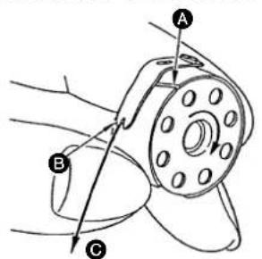
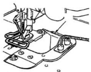
Technical line drawing of a sewing machine component with an arrow indicating upward motion (no text or symbols)9. SETTING THE BOBBIN INTO THE BOBBIN CASE
1) Install the bobbin in the bobbin case so that the thread wound direction is counterclockwise.
2) Pass the thread through thread slit A, and pull the thread in direction B. By so doing, the thread will pass under the tension spring the come out from notch B.
3) Check that the bobbin rotates in the direction of the arrow when thread Ⓐ is pulled.
DLM-5400N-7 DLM-5200N
text_image
Technical diagram of a mechanical component with labeled parts A, B, and C indicating parts of a gear or pulley assembly.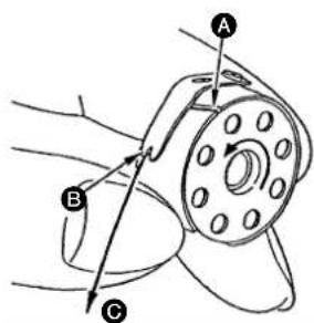
text_image
Technical diagram showing mechanical assembly with labeled parts A, B, and C, including directional arrows indicating motion or force.natural_image
Technical line drawing of a mechanical assembly with a rotating component (no text or symbols)
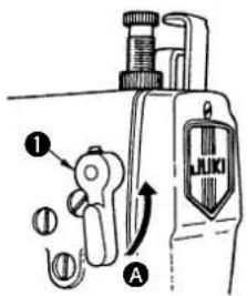
Carry out the following steps of procedure after the power switch has been turned OFF.

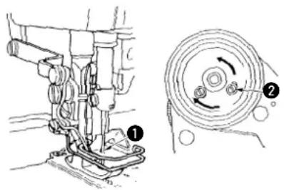
1) To stop the machine with its presser foot up, turn hand lifter lever ① in direction A.
2) The presser foot will go up about 5.5 mm and stop. The presser foot will go back to its original position when hand lifter lever is turned down in direction B.
3) Using the knee lifter, you can get the standard presser foot lift of about 10 mm and the maximum lift of about 13 mm.
text_image
Diagram of a mechanical device with labeled parts and directional arrows, including a valve labeled 'JUKI'.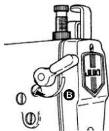
text_image
Technical diagram of a mechanical device with labeled parts and directional indicators12. ELEVADOR MANUAL
text_image
Technical diagram of a mechanical device with labeled components and dimensional annotations A and B13. MODO DE BOBINAR EL HILO DE BOBINA
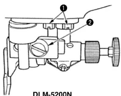
When the bobbin thread is not wound uniformly, loosen setscrew ① and adjust bobbin winder thread tension bracket ②.
- It is standard that the center of the bobbin and the that of thread tension disk ③ are in the same position.
- Adjust the position of thread tension bracket ② so that when the bobbin thread is wound more on the right side of bobbin, move the position in the direction of A and when the bobbin thread is wound more on the left side of bobbin, move the position in the direction of B.
After the adjustment, tighten setscrew 1.
13. BEWICKELN DER SPULE
Carry out the following steps of procedure after the power switch has been turned OFF.

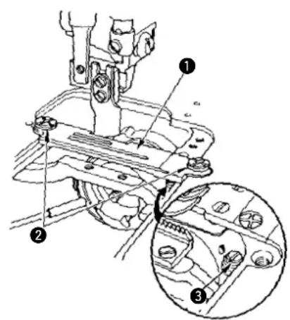
Attach waste cloth guide ① to throat plate ② so that all waste cloth drops along the waste cloth guide.
Then install oil drainage guide ③ on the oil pan, paying special attention to the following.
1) The top end of the oil drainage guide should not protrude on the left side of the extended line from the level of face A on the waste cloth cover 4.
2) Section B of the waste cloth cover should not come in contact with the oil drainage guide when the machine head is raised or tilted.
natural_image
Technical line drawing of a mechanical assembly with no visible text or symbolsDLM-5400N-7
text_image
Technical diagram of a mechanical assembly with numbered parts and directional arrows indicating motion or force directions.DLM-5200N
text_image
Technical diagram of a mechanical component with numbered parts and labeled features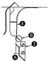
text_image
A B 3 4
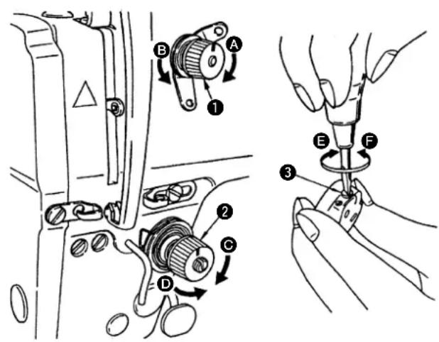
Carry out the following steps of procedure after the power switch has been turned OFF.

1. Adjusting the needle thread tension
1) As you turn thread tension No. 1 nut ① clockwise (in direction A), the thread remaining on the needle after thread trimming will be shorter.
As you turn nut ① counterclockwise (in direction B), the thread length will be longer.(DLM-5400N-7)
2) As you turn thread tension nut ② clockwise (in direction Ⓒ), the needle thread tension will be increased.
As you turn nut ② counterclockwise (in direction D), the needle thread tension will be decreased.
2. Adjusting the bobbin thread tension
1) As you turn tension adjust screw ③ clockwise (in direction E), the bobbin thread tension will be increased.
As you turn screw ③ counterclockwise (in direction F), the bobbin thread tension will be decreased.
text_image
Technical diagram showing mechanical assembly steps with labeled components A through F16. TENSION DEL HILO
Carry out the following steps of procedure after the power switch has been turned OFF.

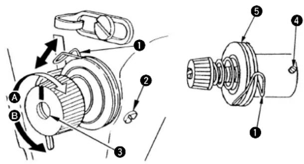
1. Changing the stroke of thread take-up spring①
1) Loosen setscrew ^2 .
2) As you turn tension post ③ clockwise (in direction A), the stroke of the thread take-up spring will be increased.
3) As you turn the knob counterclockwise (in direction B), the stroke will be decreased.
2. Changing the pressure of thread take-up spring ②
1) Loosen setscrew ^2 , and remove thread tension (asm.) 5.
2) Loosen setscrew4.
3) As you turn tension post ③ clockwise (in direction A), the pressure will be increased.
4) As you turn the post counterclockwise (in direction B), the pressure will be decreased.
text_image
Technical diagram of a mechanical assembly with labeled parts and directional arrows indicating motion or force.17. RESORTE RECOGEDOR DEL HILO
Carry out the following steps of procedure after the power switch has been turned OFF.

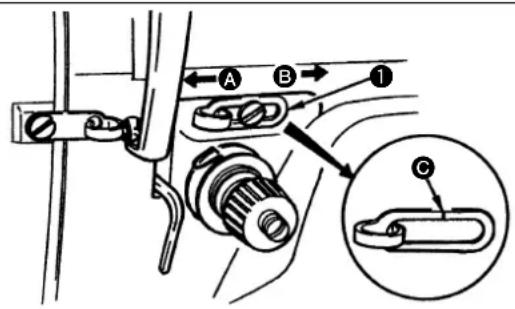
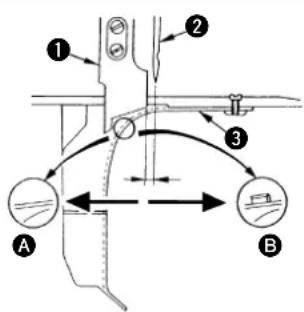
1) When sewing heavy-weight materials, move thread guide ① to the left (in direction A) to increase the length of thread pulled out by the thread take-up.
2) When sewing light-weight materials, move thread guide ① to the right (in direction B) to decrease the length of thread pulled out by the thread take-up.
3) Normally, thread guide ① is positioned in a way that marker line ② is aligned with the center of the screw.
text_image
A B 1 C18. AJUSTE DEL RECORRIDO DEL RECOGEDOR DEL HILO
Carry out the following steps of procedure after the power switch has been turned OFF.

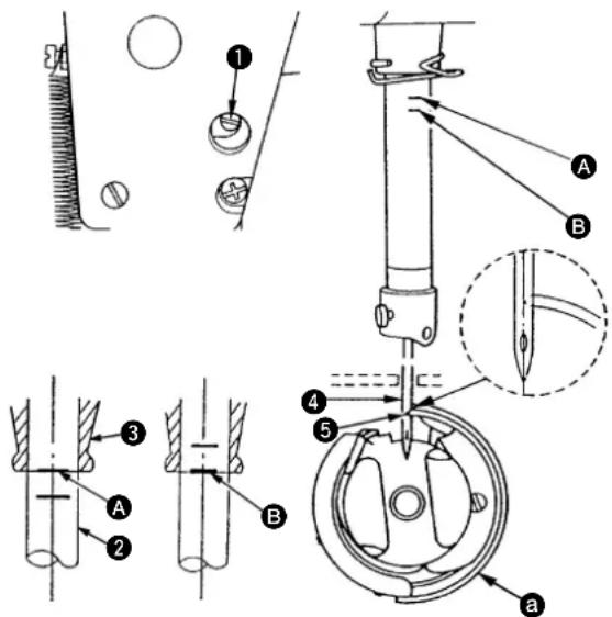
- Adjust the timing between the needle and the hook as follows :
1) Rotate the handwheel until the needle bar comes down to its lowest position, and loosen screw ①.
Be sure to set feed adjusting dial at 0 on the scale.
(Adjusting the needle bar height)
2) Align marker line A on needle bar 2 with the bottom end of needle bar lower bushing 3, then tighten setscrew 1.
(Adjusting position of the hook a)
3) Loosen the three hook setscrews. turn the handwheel, and align marker line ⑧ on ascending needle bar ② with the bottom end of needle bar lower bushing ③.
4) After making the adjustments mentioned in the above steps, align hook bade point ⑤ with the center of needle ④.
Provide a clearance of 0.04 mm to 0.1 mm (reference value) between the needle and the hook, then secutely tighten setscrews in the hook.
text_image
Technical diagram illustrating mechanical assembly steps with labeled components A, B, and numbered parts 1 to 5.
text_image
Technical diagram illustrating mechanical assembly steps with labeled components and cross-sectional views19. RELAZIONE FASE AGO/CROCHET
Carry out the following steps of procedure after the power switch has been turned OFF.

1) Loosen setscrew ①, and adjust the presser foot height and the angle of the presser foot.
2) After adjustment, securely tighten the setscrew ①.
text_image
Diagram showing mechanical components with labeled parts, including a numbered circle and circular features20. AJUSTE DE LA ALTURA DEL PRENSATELAS
Carry out the following steps of procedure after the power switch has been turned OFF.

1) Loosen screws ^2 and ^3 in feed eccentric cam ^1 , move the feed eccentric cam in the direction of the arrow or opposite direction of the arrow, and firmly tighten the screws.
2) For the standard adjustment, adjust so that the top surface of feed dog and the top end of needle eyelet are flush with the top surface of throat plate when the feed dog descends below the throat plate.
3) To advance the feed timing in order to prevent uneven material feed, move the feed eccentric cam in the direction of the arrow.
4) To delay the feed timing in order to increase stitch tightness, move the feed eccentric cam in the opposite direction from the arrow.

CAUTION: Be careful not to move the feed eccentric cam too far, or else needle breakage may result.
text_image
Technical diagram showing mechanical assembly with numbered components and corresponding cross-sectional views of threaded fasteners.21. AJUSTE DEL SONCRONISMO DEL ARRASTRE DE LAS TELAS
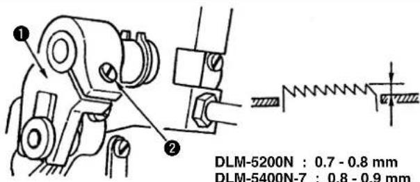
Carry out the following steps of procedure after the power switch has been turned OFF.

The standard tilt (horizontal) of the feed dog is obtained when marker dot A on the feed bar shaft is aligned with marker dot B on feed rocker 1.
text_image
Technical diagram of a mechanical assembly with labeled parts A, B, and numbered components 1 and 2, alongside corresponding schematic diagrams.To adjust the height of the feed dog :
① Loosen screw ② of crank ①.
② Move the feed bracket up or down to make adjustment.
③ Securely tighten screw ②.
text_image
① ② DLM-5200N : 0.7 - 0.8 mm DLM-5400N-7 : 0.8 - 0.9 mmCarry out the following steps of procedure after the power switch has been turned OFF.

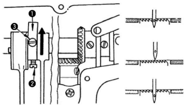
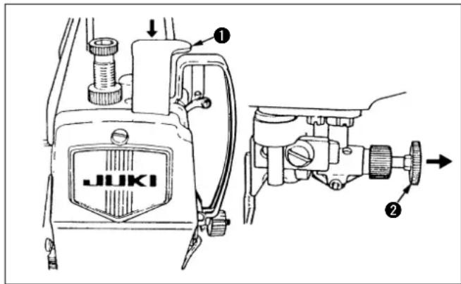
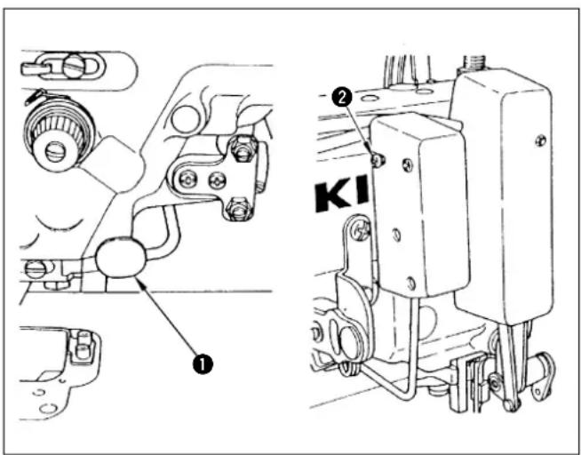
1. Operation of the cloth cutting knife (DLM-5200N)
1) To actuate the cloth cutting knife, press down knife setting plate ①. The cloth cutting knife will be lowered, and will then be actuated while the machine is being-driven.
2) To stop the cloth cutting knife and reset the machine to the normal lockstitching mode, pull knob ② in the direction of the arrow.
3) Before installing/removing the cloth cutting knife, be sure to stop the machine first.
text_image
JUKI ① ②Carry out the following steps of procedure after the power switch has been turned OFF.

1. Operation of the cloth cutting knife (DLM-5400N-7)
1) To actuate the cloth cutting knife, lower attaching/removing lever ① mounted on the machine head.
If the cloth cutting knife is lowered, it will be actuated while the machine is being driven.
2) To stop the cloth cutting knife, raise attaching/removing lever①. The cloth cutting knife will then be raised and stopped.
3) When raising or lowering the cloth cutting knife, make sure that the machine is stopped.
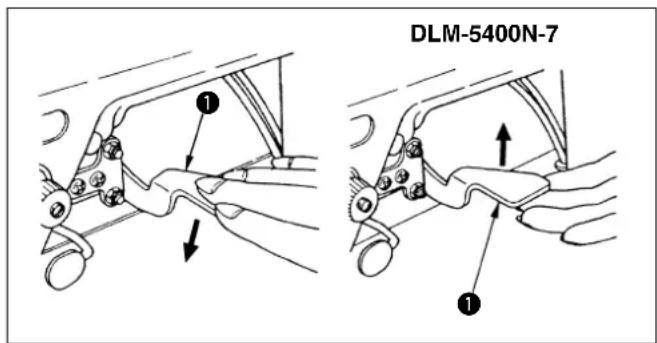
text_image
DLM-5400N-7 ① ② ③ ④ ⑤2. Attaching the cloth cutting knife
1) Attach cloth cutting knife so that section A of the cloth cutting knife is positioned 0 to 0.5 mm below the top face of the gauge when the cloth cutting knife comes down to the lowest position of its stroke.
2) Loosen two knife setscrews ①, and replace the cloth cutting knife.
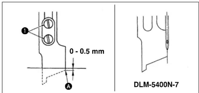
text_image
1 0 - 0.5 mm A DLM-5400N-72. Modo da colocar la cuchilla cortatelas
Carry out the following steps of procedure after the power switch has been turned OFF.

3. Changing the cutting width (DLM-5200N)
1) The gauge decides the cutting width.
When the gauge is replaced, loosen knife guiding shaft setscrew ① so that proper parallelism is obtained and the sharpness of the knife blade is increased as shown in the figure.
2) When the position of the knife is changed in accordance with the change of the gauge size, loosen setscrew ②, and position the knife so that the blade of the lower gauge comes in contact with the knife blade. Then tighten setscrew ②.
3) For the standard machine, a 3.2 mm wide gauge is installed at the time of delivery.
text_image
① ② DLM-5200N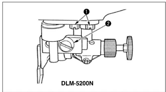
text_image
① ② DLM-5200N3. Modo de cambiar la anchura da corte (DLM-5200N)
Carry out the following steps of procedure after the power switch has been turned OFF.

text_image
Technical diagram of a sewing machine with numbered components and exploded view showing internal parts labeled A, B, and 9.3. Changing the cutting width (DLM-5400N-7)
- Six different cutting widths can be selected: 2.4 mm, 3.2 mm, 4 mm, 4.8 mm, 6.4 mm, and 9.5 mm.
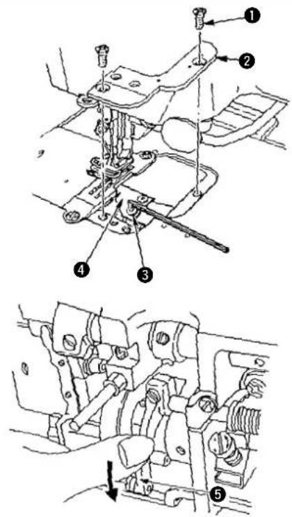
1) Remove throat plate ① (with waste cloth cover ② of the throat plate), presser foot ③, gauge ④ and feed dog ⑤.
2) Loosen knife support setscrew 6.
3) Attach the feed dog, gauge, presser foot and the waste cloth cover of the throat plate which are all necessary for establishing cutting width.
4) Turn the handwheel, and bring cloth cutting knife ⑦ to its lowest position.
5) Tighten knife support setscrew ⑥ while lightly pressing the top end of cloth cutting knife ⑦ to face A of the gauge.
(To increase the sharpness of the knife, tighten gauge setscrew 8 while pressing the gauge setscrew onto the side of the cloth cutting knife with your fingers.)
6) Loosen waste cloth cover setscrews 9 of the throat plate, and set the waste cloth cover in place so that face B of, the waste cloth covers 0 to 0.5 mm inside of face A of the gauge.
7) Tighten waste cloth cover setscrews ⑨ of the throat plate. When the cutting width is changed, be sure to use the relevant, components according to the "Table of replacement components." (Precaution)
The wiper cannot be used when the cutting width is set at 2.4 mm.
Carry out the following steps of procedure after the power switch has been turned OFF.

text_image
Technical diagram of a mechanical assembly with numbered components and directional arrows indicating parts of motion or assembly.1) Loosen setscrew⑤ of knife driving arm ①.
2) Turn the moving knife base until the engraved marker line on moving knife base ② is aligned with the engraved marker dot on front bushing ③ of the hook driving shaft.
3) When the moving knife has reached the position specified above, tighten setscrew ⑤ of the knife driving arm so that the knife driving arm is securely fixed to knife driving shaft ④.
text_image
Technical diagram of a mechanical assembly with numbered components and directional arrows indicating motion or flow.25. REGOLAZIONE DELLA POSIZIONE INIZIALE DEL COLTELLO MOBILE (DLM-5400N-7)
Carry out the following steps of procedure after the power switch has been turned OFF.

text_image
Technical diagram of a mechanical assembly with labeled parts and directional arrows
text_image
Technical diagram showing a mechanical component with labeled parts and directional arrows indicating movement or force.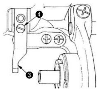
text_image
Technical diagram of a mechanical assembly with numbered components labeled 3 and 4Oil stone
Wetzstein
Pière à huile
Piedra de afi lar
Pietra da cote "oil stone"
25. REGLAGE DE LA POSITION INITIALE DU COUTEAU MOBILE (DLM-5400N-7)
1) Loosen setscrew ② of bobbin case opening lever ①, and remove the bobbin case opening lever.
2) Loosen setscrew 4, and remove counter knife 4.
3) To install the counter knife, follow the above procedure in reverse order.
4) When attaching the bobbin case opening lever, tighten the set-screw while pressing the lever in direction A.
- If the counter knife blade becomes blunt, grind counter knife blade ③ as shown in ⑧ using an oilstone.
(Caution)
When re-sharpening the knife blade, extra special care must be taken on the handling of the knife.
26. AUSWECHSELN DES GEGENMESSERS (DLM-5400N-7)
Carry out the following steps of procedure after the power switch has been turned OFF.

1) Loosen setscrews②, and remove gauge ①.
2) Turning counter knife pressure screw ③ will adjust the pressure of the counter knife.
Turning the screw clockwise will increase the pressure of the moving knife and turning the screw counterclockwise will decrease the pressure of the moving knife.
text_image
Technical diagram of a mechanical assembly with numbered components and a magnified inset view27. MODO DE AJUSTAR LA PRESION DE LA CONTRACUCHILLA (DLM-5400N-7)
Carry out the following steps of procedure after the power switch has been turned OFF.

28. REPLACING THE MOVING KNIFE (DLM-5400N-7)
1) Lift the knife attaching/removing lever so that the knife is raised.
2) Remove setscrew①, and remove throat plate②.
3) Turn the handwheel until the needle bar is raised to a point near the highest position of its stroke.
4) Press knife driving arm ⑤, and turn the moving knife until moving knife setscrew ③ comes to the top.
Hold the moving knife in that position.
5) Remove setscrew using the hexagonal wrench supplied with the unit. Then remove moving knife 4.
6) To attach the moving knife, follow the above procedure in reverse order.
text_image
Technical diagram showing mechanical assembly with numbered components and a downward arrow indicating motion or force direction.28. MODO DE CAMBIAR LA CUCHILLA MOVIL (DLM-5400N-7)
Carry out the following steps of procedure after the power switch has been turned OFF.

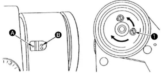
1. Stop position after thread trimming
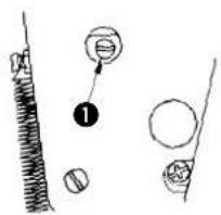
1) The standard needle stop position is obtained by aligning marker dot A on the machine arm with white marker dot B on the handwheel.
2) Stop the needle in its highest position, loosen screw ① to perform adjustment within the slot of the screw.
text_image
Technical diagram showing mechanical components with labeled parts A and B, including a circular component with directional arrows.2. Lower stop position
The lower needle stop position when the pedal is returned to the neutral position after the front part of the pedal is depressed can be adjusted as follows :
Stop need ^① in its lowest position, loosen screw ②, and make adjustment within the slot of the screw.
text_image
Technical diagram showing mechanical assembly with numbered components and rotational motion indicatorsCarry out the following steps of procedure after the power switch has been turned OFF.

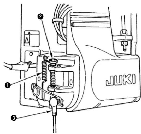
- Adjusting the pressure required to depress the front part of the pedal
This pressure can be changed by altering the mounting position of pedaling pressure adjust spring ①.
- Adjusting the pressure required to depress the back part of the pedal
This pressure can be adjusted using regulator screw ②.
- Adjusting the pedal stroke
The pedal stroke decreases when you insert connecting rod ③ into the left hole.
text_image
JUKI30. PRESION DEL PEDAL Y RECORRIDO DEL PEDAL (DLM-5400N-7)
Carry out the following steps of procedure after the power switch has been turned OFF.

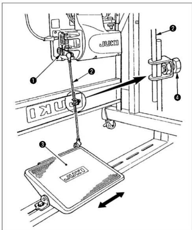
1. Installing the connecting rod
Move ped to the right or left as illustrated by the arrows so that motor control lever ① and connecting rod ② are straightened.
2. Adjusting the pedal angle
1) The pedal tilt can be freely adjusted by changing the length of the connecting rod.
2) Loosen adjust screw ④, and adjust the length of connecting rod ②.
text_image
JUKI 1 2 3 431. AJUSTE DEL PEDAL (DLM-5400N-7)
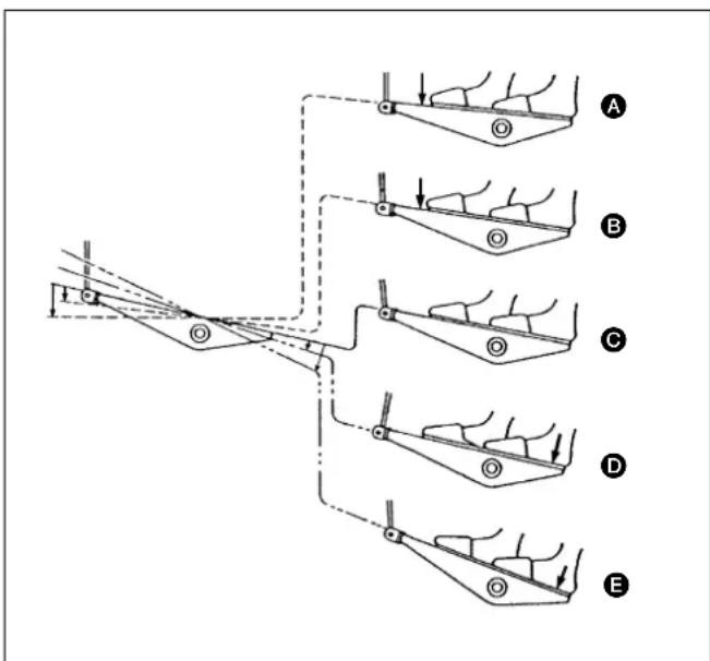
The pedal is operated in the following four steps :
1) The machine runs at low sewing speed when you lightly depress the front part of the pedal. B
2) The machine runs at high sewing speed when you further depress the front part of the pedal. A (If the automatic reverse feed stitching has been preset, the machine runs at high speed after it completes reverse feed stitching.)
3) The machine stops (with its needle up or down) when you reset the pedal to its original position. ©
4) The machine trims threads when you fully depress the back part of the pedal.
* If your machine is provided with the Auto-lifter (AK Series), an addition step is given between the machine stop and thread trimming step. The presser foot goes up when you lightly depress the back part of the pedal D, and if you further depress the back part, the thread trimmer is actuated.
text_image
Technical diagram showing five labeled mechanical or structural components (A–E) with arrows indicating movement or assembly.1) The moment switch lever ① is pressed, the machine performs reverse feed stitching.
2) The machine performs reverse feed stitching as long as the switch lever is held depressed.
3) The machine resumes normal feed stitching the moment the switch lever is released.

Carry out the following steps of procedure after the power switch has been turned OFF.
2. Height of the switch lever
1) Adjust the height of switch lever ① so that it can be easily operated.
2) Loosen screw ^② , and move the switch lever up or down to adjust its height.
text_image
Technical diagram showing mechanical assembly with labeled parts, including numbered annotations ① and ②.33. MECANISMO DEL RETROCESO DE UN TOQUE (DLM-5400N-7)
1. Operación
Carry out the following steps of procedure after the power switch has been turned OFF.

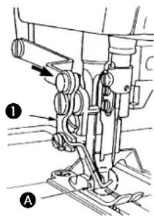
1. Positioning the wiper
1) Before you use the wiper be sure that the wiper is in contact with point A of the presser foot.
2) If the wiper is not in contact with point A, the needle may break. To avoid this, loosen screws ②, push wiper arm ① in the direction of the arrow, then tighten screws ②.
text_image
Technical diagram of a mechanical assembly with labeled parts and directional arrow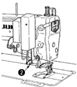
natural_image
Technical line drawing of a sewing machine with no visible text or symbols34. SCARTAFILO (DLM-5400N-7)
Carry out the following steps of procedure after the power switch has been turned OFF.

2. How to connect the wiper with the presser foot
1) Attach the wiper arm to the presser foot using screw ③.
2) Attach wiper④ to the wiper arm using setscrew ⑤.
(Precaution)
After installing the wiper, be sure that wiper ④ does not touch the cloth cutting knife. If the wiper comes in contact with the cloth cutting knife, correct wiper ④.
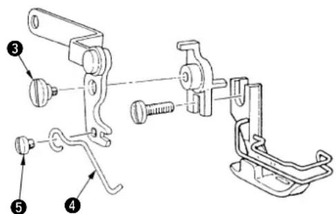
text_image
Technical diagram of a mechanical clamp assembly with numbered parts labeled 3, 4, and 5Carry out the following steps of procedure after the power switch has been turned OFF.

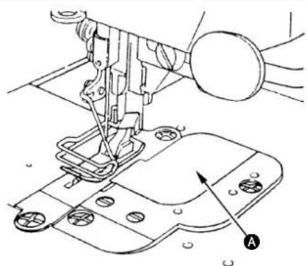
35. OTHER REPLACEMENT PARTS
1. Throat plate cover
1) When the cloth cutting knife is not in use, fit the throat plate cover, which is provided as an accessory, onto the throat plate, and press A portion from above.
2) The throat plate cover is now securely fixed, and the hole for the waste cloth is closed.
(Precaution)
The throat plate cover, which is provided as an accessory, may touch the cloth cutting knife when cloth chips are not dropped underneath the bed, even if the cloth cutting knife is used.
Therefore, the throat plate cover need to be cut as necessary or a throat plate cover with a large gauge width should be used.
natural_image
Technical line drawing of a sewing machine with no visible text or symbolsCarry out the following steps of procedure after the power switch has been turned OFF.

2. Throat plate cloth chip cover (without a knife escape hole)
1) The throat plate cloth chip cover (without a knife escape hole) is used only when the cloth cutting knife is used at a position 1 mm or more behind the center of the needle.
(Precaution)
Be sure to use the throat plate cloth chip cover (without a knife escape hole) if the cloth cutting knife is to be used at a position 1 mm or less behind the center of the needle or in front of the center of the needle.
text_image
Technical diagram showing three labeled components (A, B, 1, 2) with directional arrows and circular indicators indicating movement or flow.2. Cubeta da briznas da tela de la placa da agujas (sin agujero de escape de cuchilla)
Carry out the following steps of procedure after the power switch has been turned OFF.

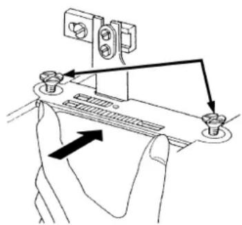
- To attach the gauge, bring the cloth cutting knife to its lowest position, and gradually tighten the two setscrews alternately while lightly pressing the gauge onto the cloth cutting knife.
natural_image
Hand holding a device with arrows indicating motion or force direction (no text or symbols)SEWING MACHINERY BUSINESS UNIT
2-11-1, TSURUMAKI, TAMA-SHI.
Copyright © 2010-2013 JUKI CORPORATION
- All rights reserved throughout the world.
- Alle Rechte weltweit vorbehalten.
- Tous droits réservés partout dans le monde.
- Reservados todos derechos en el mundo entero.
• Tutti i diritti sono riservati in tutto il mondo.
Please do not hesitate to contact our distributors or agents in your area for further information when necessary.
* The description covered in this instruction manual is subject to change for improvement of the commodity without notice.
Bitte wenden Sie sich an unsere Händler oder Vertreter in Ihrer Nähe, wenn Sie weitere Informationen benötigen.
* Änderungen der in dieser Betriebsanleitung enthaltenen Beschreibungen, die der Verbesserung des Produktes dienen, bleiben vorbehalten.
Pour plus d'information, n'hésitez pas à consulter nos distributeurs ou agents dans votre région.
* Les spécifications données dans le présent Manuel d'utilisation sont sujettes à modification sans préavis.
Sírvase ponerse en contacto con nuestros distribuidores o agentes en su área siempre que necesite alguna información más detallada.
* La descripción que se de en este manual de instrucciones está sujeta a cambio sin previo aviso por razones de mejora de la mercancía.
Per ulteriore informazione, si prega di non esitare a mettersi in contatto con nostri distributori o agenti vo-stra area quando necessario.
* Le descrizioni contenute in questo manuale d' istruzioni sono soggette a modifiche senza alcun preavviso.