
DSC-244 - Sewing machine JUKI - Free user manual and instructions
Find the device manual for free DSC-244 JUKI in PDF.


| Product Type | Industrial Sewing Machine |
| Model | DSC-244 |
| Machine Type | Cylinder-bed, 1-needle, unison-feed lockstitch |
| Max Sewing Speed | 2,200 sti/min |
| Stitch Length | 0 to 6 mm |
| Presser Foot Lift | Hand lifter: 9 mm, Knee lifter: 15 mm |
| Needle Bar Stroke | 36 mm |
| Needle System | #50 to #20 |
| Needle Type | GROZ-BECKERT 135×17 (Nm90 to Nm130, standard Nm110) |
| Lubrication Method | By oiler and oil wick centralized in face plate |
| Recommended Oil | New Defrix Oil No.1 |
| Motor Type | 400W Electro-stop motor (4P) |
| Power Supply | 3-phase AC, 50/60 Hz |
| Weight (approx.) | 45 kg |
| Sound Pressure Level (LpA) | 83.5 dB(A) at workstation |
| Sound Power Level (LwA) | 89.5 dB(A) |
| Application | Medium to heavy weight materials |
| Safety Features | Finger guard, eye guard, safety covers, earth cable, warning labels |
| Maintenance | Regular oiling, cleaning, periodic inspection of moving parts |
| Spare Parts | JUKI genuine parts recommended; full list in manual |
Frequently Asked Questions - DSC-244 JUKI
User questions about DSC-244 JUKI
0 question about this device. Answer the ones you know or ask your own.
Ask a new question about this device
Download the instructions for your Sewing machine in PDF format for free! Find your manual DSC-244 - JUKI and take your electronic device back in hand. On this page are published all the documents necessary for the use of your device. DSC-244 by JUKI.
USER MANUAL DSC-244 JUKI
NOTE : Read safety instructions carefully and understand them before using. Retain this Instruction Manual for future reference.
TO ENSURE SAFE USE OF YOUR SEWING MACHINE
For the sewing machine, automatic machine and ancillary devices (hereinafter collectively referred to as "machine"), it is inevitable to conduct sewing work near moving parts of the machine. This means that there is always a possibility of unintentionally coming in contact with the moving parts. Operators who actually operate the machine and maintenance personnel who are involved in maintenance and repair of the machine are strongly recommended to carefully read to fully understand the following SAFETY PRECAUTIONS before using/maintaining the machine. The content of the SAFETY PRECAUTIONS includes items which are not contained in the specifications of your product.
The risk indications are classified into the following three different categories to help understand the meaning of the labels. Be sure to fully understand the following description and strictly observe the instructions.
( I ) Explanation of risk levels
 | DANGER :This indication is given where there is an immediate danger of death or serous injury if the person in charge or any third party mishandles the machine or does not avoid the dangerous situation when operating or maintaining the machine. |
 | WARNING :This indication is given where there is a potentiality for death or serious injury if the person in charge or any third party mishandles the machine or does not avoid the dangerous situation when operating or maintaining the machine. |
 | CAUTION :This indication is given where there is a danger of medium to minor injury if the person in charge or any third party mishandles the machine or does not avoid the dangerous situation when operating or maintaining the machine. |
 | Items requiring special attention. |
(II) Explanation of pictorial warning indications and warning labels
| Pictorial warning indication |  | There is a risk of injury if contact-ing a moving section. | Pictorial warning indication | Be aware that holding the sewing machine during operation can hurt your hands. | |
 | There is a risk of electrical shock if contacting a high-voltage section. | There is a risk of entanglement in the belt resulting in injury. | |||
 | There is a risk of a burn if contact-ing a high-temperature section. | There is a risk of injury if you touch the button carrier. | |||
 | Be aware that eye deficiency can be caused by looking directly at the laser beam. | Indication label | The correct direction is indicated. | ||
 | There is a risk of contact between your head and the sewing ma-chine. | Connection of a earth cable is indicated. |
| Warning label |  1• There is the possibility that slight to serious injury or death may be caused.• There is the possibility that injury may be caused by touching moving part.2• To perform sewing work with safety guard.• To perform sewing work with safety cover.• To perform sewing work with safety protection device.3• Be sure to turn the power OFF before carrying out "machine-head threading", "needle changing", "bobbin changing" or "oiling and cleaning". 1• There is the possibility that slight to serious injury or death may be caused.• There is the possibility that injury may be caused by touching moving part.2• To perform sewing work with safety guard.• To perform sewing work with safety cover.• To perform sewing work with safety protection device.3• Be sure to turn the power OFF before carrying out "machine-head threading", "needle changing", "bobbin changing" or "oiling and cleaning". | 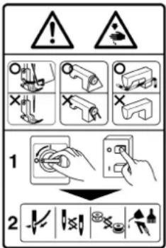 ←1←2←3 ←1←2←3 |
| Electrical-shock danger label | 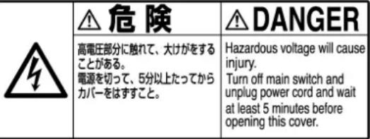 |

DANGER
- When it is necessary to open the control box containing electrical parts, be sure to turn the power off and wait for five minutes or more before opening the cover in order to prevent accident leading to electrical shock.

CAUTION
Basic precaution
- Be sure to read the instruction manual and other explanatory documents supplied with accessories of the machine before using the machine. Carefully keep the instruction manual and the explanatory documents at hand for quick reference.
- The content of this section includes items which are not contained in the specifications of your product.
- Be sure to wear safety goggles to protect against accident caused by needle breakage.
- Those who use a heart pacer have to use the machine after consultation with a medical specialist.
Safety devices and warning labels
- Be sure to operate the machine after verifying that safety device(s) is correctly installed in place and works normally in order to prevent accident caused by lack of the device(s).
- If any of the safety devices is removed, be sure to replace it and verify that it works normally in order to prevent accident that can result in personal injury or death.
- Be sure to keep the warning labels adhered on the machine clearly visible in order to prevent accident that can result in personal injury or death. If any of the labels has stained or come unstuck, be sure to change it with a new one.
Application and modification
- Never use the machine for any application other than its intended one and in any manner other than that prescribed in the instruction manual in order to prevent accident that can result in personal injury or death. JUKI assumes no responsibility for damages or personal injury or death resulting from the use of the machine for any application other than the intended one.
- Never modify and alter the machine in order to prevent accident that can result in personal injury or death. JUKI assumes no responsibility for damages or personal injury or death resulting from the machine which has been modified or altered.
Education and training
- In order to prevent accident resulting from unfamiliarity with the machine, the machine has to be used only by the operator who has been trained/educated by the employer with respect to the machine operation and how to operate the machine with safety to acquire adequate knowledge and operation skill. To ensure the above, the employer has to establish an education/training plan for the operators and educate/train them beforehand.
Items for which the power to the machine has to be turned off
Turning the power off: Turning the power switch off, then removing the power plug from the outlet. This applies to the following.
- Be sure to immediately turn the power off if any abnormality or failure is found or in the case of power failure in order to protect against accident that can result in personal injury or death.
- To protect against accident resulting from abrupt start of the machine, be sure to carry out the following operations after turning the power off. For the machine incorporating a clutch motor, in particular, be sure to carry out the following operations after turning the power off and verifying that the machine stops completely.
2-1. For example, threading the parts such as the needle, looper, spreader etc. which have to be threaded, or changing the bobbin.
2-2. For example, changing or adjusting all component parts of the machine.
2-3. For example, when inspecting, repairing or cleaning the machine or leaving the machine. - Be sure to remove the power plug by holding the plug section instead of the cord section in order to prevent electrical-shock, earth-leakage or fire accident.
- Be sure to turn the power off whenever the machine is left unattended between works.
- Be sure to turn the power off in the case of power failure in order to prevent accident resulting of breakage of electrical components.
PRECAUTIONS TO BE TAKEN IN VARIOUS OPERATION STAGES
Transportation
- Be sure to lift and move the machine in a safe manner taking the machine weight in consideration. Refer to the text of the instruction manual for the mass of the machine.
- Be sure to take sufficient safety measures to prevent falling or dropping before lifting or moving the machine in order to protect against accident that can result in personal injury or death.
- Once the machine has been unpacked, never re-pack it for transportation to protect the machine against breakage resulting from unexpected accident or dropping.
Unpacking
- Be sure to unpack the machine in the prescribed order in order to prevent accident that can result in personal injury or death. In the case the machine is crated, in particular, be sure to carefully check nails. The nails have to be removed.
- Be sure to check the machine for the position of its center of gravity and take it out from the package carefully in order to prevent accident that can result in personal injury or death.
Installation
(I) Table and table stand
- Be sure to use JUKI genuine table and table stand in order to prevent accident that can result in personal injury or death. If it is inevitable to use a table and table stand which are not JUKI genuine ones, select the table and table stand which are able to support the machine weight and reaction force during operation.
- If casters are fitted to the table stand, be sure to use the casters with a locking mechanism and lock them to secure the machine during the operation, maintenance, inspection and repair in order to prevent accident that can result in personal injury or death.
(II) Cable and wiring
- Be sure to prevent an extra force from being applied to the cable during the use in order to prevent electrical-shock, earth-leakage or fire accident. In addition, if it is necessary to cable near the operating section such as the V-belt, be sure to provide a space of 30 mm or more between the operating section and the cable.
- Be sure to avoid starburst connection in order to prevent electrical-shock, earth-leakage or fire accident.
- Be sure to securely connect the connectors in order to prevent electrical-shock, earth-leakage or fire accident. In addition, be sure to remove the connector while holding its connector section.
(III) Grounding
- Be sure to have an electrical expert install an appropriate power plug in order to prevent accident caused by earth-leakage or dielectric strength voltage fault. In addition, be sure to connect the power plug to the grounded outlet without exceptions.
- Be sure to ground the earth cable in order to prevent accident caused by earth leakage.
(IV) Motor
- Be sure to use the specified rated motor (JUKI genuine product) in order to prevent accident caused by burnout.
- If a commercially available clutch motor is used with the machine, be sure to select one with an entanglement preventive pulley cover in order to protect against being entangled by the V-belt.
Before operation
- Be sure to make sure that the connectors and cables are free from damage, dropout and looseness before turning the power on in order to prevent accident resulting in personal injury or death.
- Never put your hand into the moving sections of the machine in order to prevent accident that can result in personal injury or death. In addition, check to be sure that the direction of rotation of the pulley agrees with the arrow shown on pulley.
- If the table stand with casters is used, be sure to secure the table stand by locking the casters or with adjusters, if provided, in order to protect against accident caused by abrupt start of the machine.
During operation
- Be sure not to put your fingers, hair or clothing close to the moving sections such as the handwheel, hand pulley and motor or place something near those sections while the machine is in operation in order to prevent accident caused by entanglement that can result in personal injury or death.
- Be sure not to place your fingers near the surround area of the needle or inside the thread take-up lever cover when turning the power on or while the machine is in operation in order to prevent accident that can result in personal injury or death.
- The machine runs at a high speed. Never bring your hands near the moving sections such as looper, spreader, needle bar, hook and cloth trimming knife during operation in order to protect your hands against injury. In addition, be sure to turn the power off and check to be sure that the machine completely stops before changing the thread.
-
Be careful not to allow your fingers or any other parts of your body to be caught between the machine and table when removing the machine from or replacing it on the table in order to prevent accident that can result in personal injury or death.
-
Be sure to turn the power off and check to be sure that the machine and motor completely stop before removing the belt cover and V-belt in order to prevent accident caused by abrupt start of the machine or motor.
- If a servomotor is used with the machine, the motor does not produce noise while the machine is at rest. Be sure not to forget to turn the power off in order to prevent accident caused by abrupt start of the motor.
- Never use the machine with the cooling opening of the motor power box shielded in order to prevent fire accident by overheat.
Lubrication
- Be sure to use JUKI genuine oil and JUKI genuine grease to the parts to be lubricated.
- If the oil adheres on your eye or body, be sure to immediately wash it off in order to prevent inflammation or irritation.
- If the oil is swallowed unintentionally, be sure to immediately consult a medical doctor in order to prevent diarrhea or vomiting.
Maintenance
- In prevention of accident caused by unfamiliarity with the machine, repair and adjustment has to be carried out by a service technician who is thoroughly familiar with the machine within the scope defined in the instruction manual. Be sure to use JUKI genuine parts when replacing any of the machine parts. JUKI assumes no responsibility for any accident caused by improper repair or adjustment or the use of any part other than JUKI genuine one.
- In prevention of accident caused by unfamiliarity with the machine or electrical-shock accident, be sure to ask an electrical technician of your company or JUKI or distributor in your area for repair and maintenance (including wiring) of electrical components.
- When carrying out repair or maintenance of the machine which uses air-driven parts such as an air cylinder, be sure to remove the air supply pipe to expel air remaining in the machine beforehand, in order to prevent accident caused by abrupt start of the air-driven parts.
- Be sure to check that screws and nuts are free from looseness after completion of repair, adjustment and part replacement.
- Be sure to periodically clean up the machine during its duration of use. Be sure to turn the power off and verify that the machine and motor stop completely before cleaning the machine in order to prevent accident caused by abrupt start of the machine or motor.
- Be sure to turn the power off and verify that the machine and motor stop completely before carrying out maintenance, inspection or repair of the machine. (For the machine with a clutch motor, the motor will keep running for a while by inertia even after turning the power off. So, be careful.)
- If the machine cannot be normally operated after repair or adjustment, immediately stop operation and contact JUKI or the distributor in your area for repair in order to prevent accident that can result in personal injury or death.
- If the fuse has blown, be sure to turn the power off and eliminate the cause of blowing of the fuse and replace the blown fuse with a new one in order to prevent accident that can result in personal injury or death.
- Be sure to periodically clean up the air vent of the fan and inspect the area around the wiring in order to prevent fire accident of the motor.
Operating environment
- Be sure to use the machine under the environment which is not affected by strong noise source (electromagnetic waves) such as a high-frequency welder in order to prevent accident caused by malfunction of the machine.
- Never operate the machine in any place where the voltage fluctuates by more than "rated voltage ± 10% in order to prevent accident caused by malfunction of the machine.
- Be sure to verify that the air-driven device such as an air cylinder operates at the specified air pressure before using it in order to prevent accident caused by malfunction of the machine.
- To use the machine with safety, be sure to use it under the environment which satisfies the following conditions:
Ambient temperature during operation 5°C to 35°C
Relative humidity during operation 35 % to 85 %
-
Dew condensation can occur if bringing the machine suddenly from a cold environment to a warm one. So, be sure to turn the power on after having waited for a sufficient period of time until there is no sign of water droplet in order to prevent accident caused by breakage or malfunction of the electrical components.
-
Be sure to stop operation when lightning flashes for the sake of safety and remove the power plug in order to prevent accident caused by breakage or malfunction of the electrical components.
-
Depending on the radio wave signal condition, the machine may generate noise in the TV or radio. If this occurs, use the TV or radio with kept well away from the machine.
-
In order to ensure the work environment, local laws and regulations in the country where the sewing machine is installed shall be followed. In the case the noise control is necessary, an ear protector or other protective gear should be worn according to the applicable laws and regulations.
-
Disposal of products and packages and treatment of used lubricating oil should be carried out properly according to the relevant laws of the country in which the sewing machine is used.
FOR SAFE OPERATION
 | 1. To avoid personal injury, never put your fingers under the needle when you turn ON the power switch or operate the sewing machine.2. To avoid personal injury, never put your fingers into the thread take-up cover while the sewing machine is in operation.3. Turn OFF the power switch when tilting the machine head, or removing the belt cover or the V belts.4. To prevent possible personal injury caused by being caught in the machine, keep your fingers, head and clothes away from the handwheel and the thread take-up while the sewing machine is in operation. In addition, place nothing around it.5. To avoid personal injury, never operate the sewing machine with the finger guard removed.6. To avoid personal injury, be careful not to allow your fingers in the machine when tilting the machine head. |
 | 1. For the safety, never operate the sewing machine with the ground wire for the power supply removed.2. Be sure to turn OFF the power switch in prior when connecting/disconnecting the power plug.3. When thunders occurs, stop the work for the safety and disconnect the power plug.4. When the sewing machine is suddenly moved from a cold place to a warm place, there is a case where dew condensation may occur. Turn ON the power after there is no worry of the drop of water.5. To prevent fires, periodically draw out the power plug from the plug socket and clean the root of the pins and the space between pins.6. The hook rotates at a high speed while the machine is in operation. To prevent possible injury to hands, be sure to keep your hands away from the vicinity of the hook during operation. In addition, be sure to turn OFF the power to the machine when replacing the bobbin.7. To avoid possible accidents due to abrupt start of the machine, be sure to turn OFF the power to the machine.8. Be careful of handling this product so as not to pour water or oil, shock by dropping, and the like since this product is a precision instrument.9. When tilting or returning the sewing machine to the home position, hold the upper side of the machine head with both hands and perform the work quietly so that fingers or the like are not caught in the machine. |

CAUTION :
Note that safety devices such as “eye guard”, “finger guard”, etc. may be omitted from the illustrations in this Instruction Manual for easy explanation.
When operating the machine, be sure not to remove these safety devices.

CAUTION : Check the following so as to prevent maloperation of and damage to the machine.
- Before you put the machine into operation for the first time after the set-up, clean it thoroughly. Remove all dust gathering during transportation and oil it well.
- Confirm that voltage has been correctly set. Confirm that the power plug has been properly connected to the power supply.
- Never use the machine in the state where the voltage type is different from the designated one.
- The direction of normal rotation of the machine is counterclockwise as observed from the pulley side. Take care not to allow the machine to rotate in the reverse direction.
- Never operate the machine unless the machine head and the oil tank have been filled with oil.
- For a test run, remove the bobbin and the needle thread.
- For the first month, decrease the sewing speed and run the sewing machine at a speed of 2,000 sti/min or less.
- Operate the handwheel after the machine has totally stopped.
DECLARATION OF INCORPORATION OF PARTLY COMPLETED MACHINERY
We hereby declare that the sewing machine (sewing head) described below ;
- Must not be put into service until the machinery to which it is incorporated has been declared in conformity with the provisions of the Directive 2006/42/EC, and
- Conforms to the essential requirements of the Directive 2006/42/EC, described in the technical documentation, and
- To be prepared with the above technical documentation compiled in accordance with part B of Annex VII, and
- Also to conform to the RoHS Directive 2011/65/EU
- Relevant information on which should be transmitted in response to a reasoned request by the national authorities, by the electronic method or other according to the request.
Model
DSC-240 Series
Description Industrial Sewing Machine
Function make stitches and sew
Applied harmonized standards, in particular :
EN ISO12100, EN ISO10821, EN 50581
Manufacturer :
JUKI CORPORATION
2-11-1, Tsurumaki, Tama-shi, Tokyo, Japan
CONTENTS
SPECIFICATIONS....1
- SETTING UP THE SEWING MACHINE .... 1
- INSTALLING THE THREAD STAND 2
- INSTALLING THE BELT COVER AND THE BOBBIN WINDER 2
- LUBRICATOIN .... 3
- ATTACHING THE NEEDLE 4
- WINDING A BOBBIN .... 4
- THREADING THE BOBBIN CASE......4
- INSTALLING THE TAKE-UP THREAD GUIDE ROD .... 5
- THREAD THE MACHINE HEAD......5
- ADJUSTING THE STITCH LENGTH 5
- FORWARD/REVERSE SEAM RATIO......6
- THREAD TENSION....6
- THREAD TAKE-UP SPRING 6
- PRESSURES OF THE PRESSER FOOT AND WALKING FOOT...... 7
- HEIGHT OF THE FEED DOG (DSC-244) 7
- ADJUSTING THE WALKING FOOT AND THE PRESSER FOOT 8
- NEEDLE-TO-HOOK RELATIONSHIP....9
- HOW TO CHANGE FROM ELLIPTICAL FEED TO HORIZONTAL FEED 10
- HOW TO CHANGE FROM HORIZONTAL FEED TO ELLIPTICAL FEED 12
- MOTOR PULLEY AND SEWING SPEED 14
- TROUBLES AND CORRECTIVE MEASURES ...... 14
SPECIFICATIONS
| Model DSC-244 | DSC-244V | |
| Type of sewing machine head | Cylinder-bed, 1-needle, unison-feed lockstitch machine | Cylinder-bed, 1-needle, unison-feed lockstitch machine (horizontal drop feed) |
| Usage Suited for sewing | medium-to heavy weight materials | |
| Sewing speed Max. 2,200 sti/min | ||
| Stitch length 0 to 6 mm | ||
| Lift of presser foot Hand lifter | : 9 mm、Knee lifter : 15 mm | |
| Thread take-up lever Slide type thread take-up | ||
| Needle bar stroke 36 mm | ||
| Needle to be used GROZ-BECKERT 135×17 Nm90 to Nm130 (Standard Nm110) | ||
| Needle system #50 to #20 | ||
| Stitch adjusting method Dial | ||
| Lubrication method By an oiler and an oil wick centralized in face plate | ||
| Motor to be used 400W Electro-stop motor (4P) | ||
| Oil to be used New Defrix Oil No.1 | ||
| Noise - Equivalent continuous emission sound pressure level (LpA) at the workstation : A-weighted value of 83.5 dB; (Includes KpA = 2.5 dB); according to ISO 10821-C.6.2 -ISO 11204 GR2 at 2,200 sti/min.- Sound power level (LwA) ; A-weighted value of 89.5 dB; (Includes KwA = 2.5 dB); according to ISO 10821-C.6.2 -ISO 3744 GR2 at 2,200 sti/min. | - Equivalent continuous emission sound pressure level (LpA) at the workstation : A-weighted value of 80.0 dB; (Includes KpA = 2.5 dB); according to ISO 10821-C.6.2 -ISO 11204 GR2 at 2,200 sti/min. | |
1. SETTING UP THE SEWING MACHINE
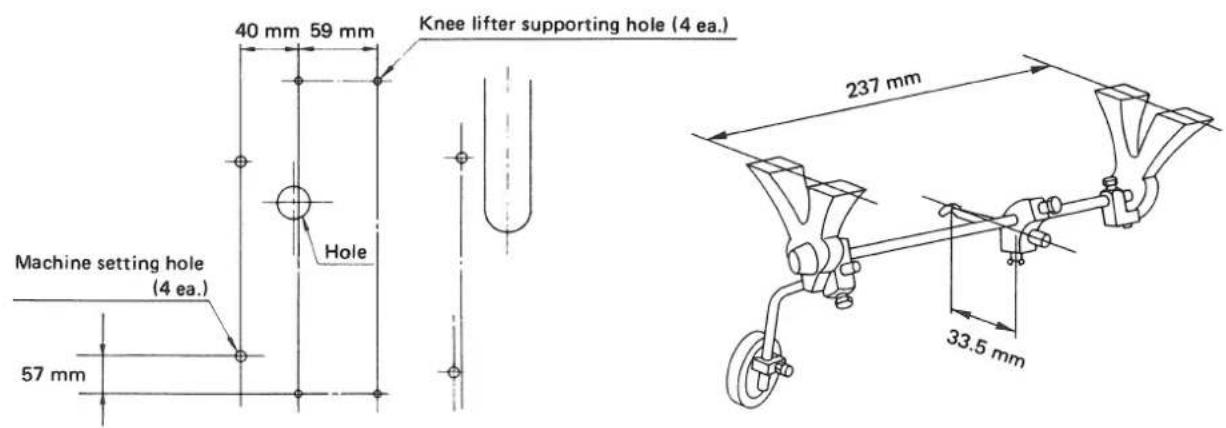

- Mounting position of the knee lifter
(Caution) The knee lifter should be mounted before the moter is installed.
- Carry the sewing machine with two persons.
(Caution) Do not hold the handwheel.
-
Do not put protruding articles such as the screwdriver and the like at the location where the sewing machine is placed.
-
Setting the sewing machine
Holding countersunk screw ①, washer ② and nut ③ supplied with the unit, fix the sewing machine on the table with aligned with rubber packing ④ at four locations.
- Securely attach head support rod to the table until it goes no further.
2. INSTALLING THE THREAD STAND

- Assemble the thread stand, and insert it in the hole in the machine table, and fix it by tightening nut ①.
3. INSTALLING THE BELT COVER AND THE BOBBIN WINDER

WARNING :
To protect against possible personal injury due to abrupt start of the machine, be sure to start the following work after turning the power off and ascertaining that the motor is at rest.
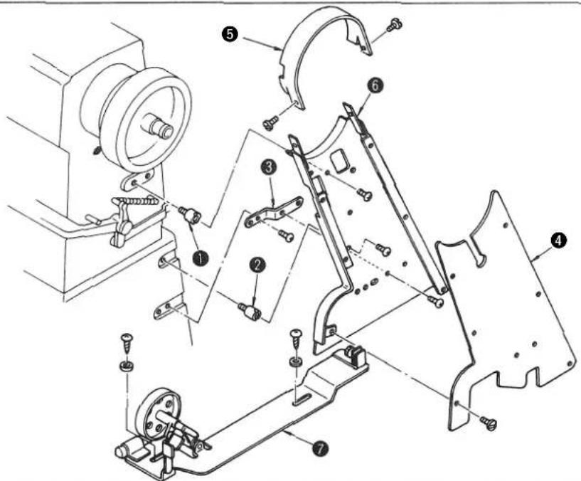
- Insert support ① of the belt cover into the tapped hole in the machine arm. Install belt cover support ② and belt cover support plate ③ in the tapped holes in the machine bed.
- Hook the V belt on the pulley.
- Attach belt cover 6.
- Attach top cover ⑤.
- Place bobbin winder ⑦ inside the belt cover. Adjust the position of the bobbin winder so that it does not come in contact
- with the sewing machine and the belt cover. Then fix the bobbin winder using the wooden screws.
Attach rid ④ of the belt cover. - Tilt the machine head, and confirm that the belt cover does not come in contact with the belt groove in the table.
(Caution) Before tilting the machine head, remove the hook for the knee lifter.
4. LUBRICATION

WARNING :
To protect against possible personal injury due to abrupt start of the machine, be sure to start the following work after turning the power off and ascertaining that the motor is at rest.
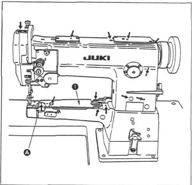
• Before starting the sewing machine
- Prior to operation, be sure to properly lubricate the points marked with the arrows.
(Caution) Lubrication to section A: For the DSC-244V, pull bed top face cover ① toward you, then lubricate section A.

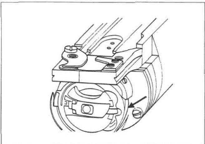
• Lubricating the hook
- Remove the hook cover.
- Apply a few drops of oil everyday to the hook race surface shown with the arrow in the figure at the left.
5. ATTACHING THE NEEDLE

WARNING :
To protect against possible personal injury due to abrupt start of the machine, be sure to start the following work after turning the power off and ascertaining that the motor is at rest.
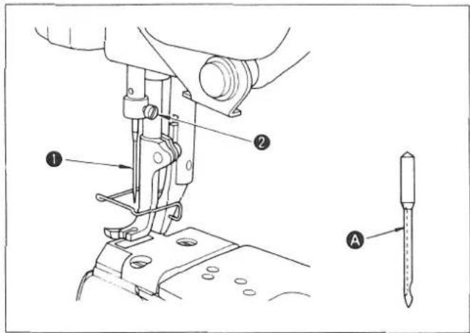
• Turn the motor power OFF
The standard needle is GROZ-BECKERT 135 x 17 Nm110.
- Turn the handwheel to move the needle bar up to its highest position.
- Loosen needle setscrew ②, and hold needle ① so that long groove A faces exactly to the left.
- Insert the needle into the needle bar until it will go no further. Securely tighten the needle setscrew.
6. WINDING A BOBBIN
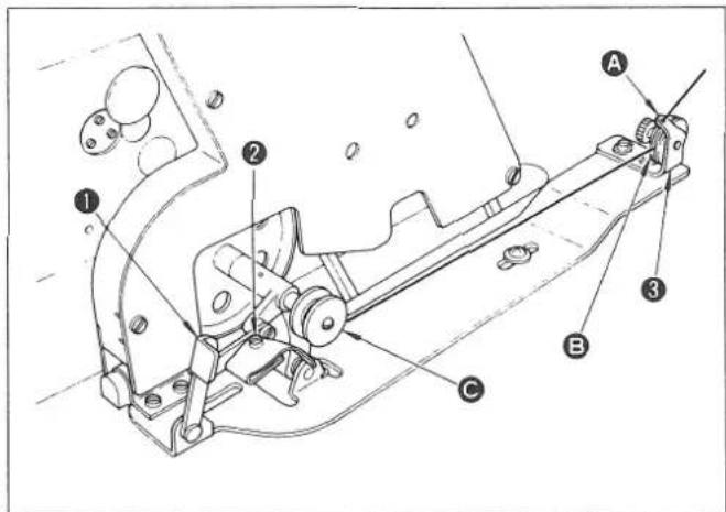
- Route the thread in the order of A, B and C before winding it round the bobbin several times.
- Set bobbin presser ① down to bring the winder in contact with the belt.
- Adjust screw ② so that the bobbin is wound with thread about 80%. Turning the screw clockwise increases the amount of thread wound on the bobbin, and vice versa.
- If thread is wound unevenly, move winder tension adjustor base ③ to the right or left to correct it.
- The moment the bobbin has been wound up, the bobbin presser is released, and the bobbin winder will stop automatically.
7. THREADING THE BOBBIN CASE

- Removing the bobbin case
Raise the bobbin case latch to remove the bobbin case.
• Threading the bobbin case
- Pass the thread through threading slit ① in the bobbin case, and route it under tension spring ②.
- Hold the latch of the bobbin case, and set the bobbin case into the hook.
(Caution) When setting the bobbin in the bobbin case, pay attention to the winding direction of the bobbin thread.
(When the bobbin is correctly set in the bobbin, the bobbin turns in the direction of arrow ③ by pulling the thread in the direction of arrow A.)
8. INSTALLING THE TAKE-UP THREAD GUIDE ROD
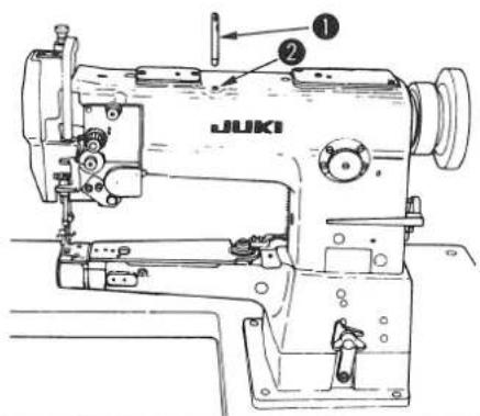
Insert take-up thread guide rod ① (attaching section is tapered off) into attaching hole ②.
9. THREAD THE MACHINE HEAD

WARNING :
To protect against possible personal injury due to abrupt start of the machine, be sure to start the following work after turning the power off and ascertaining that the motor is at rest.
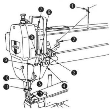
Thread the machine head in the order of ① through to ⑫.
10. ADJUSTING THE STITCH LENGTH

Turn feed adjustment dial ① in the left (right) until the desired value is aligned with the white marker dot.
• How to engage the reverse feed stitching
- Push feed lever ② down.
- The machine performs reverse feed stitching as long as the lever is held depressed.
- The moment you release the lever, the machine resumes the normal stitching mode.
11. FORWARD/REVERSE SEAM RATIO

WARNING :
To protect against possible personal injury due to abrupt start of the machine, be sure to start the following work after turning the power off and ascertaining that the motor is at rest.
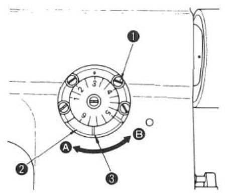
The seam ratio of forward stitch and reverse stitch is adjusted to be 1:1, but sometimes it shifts according to the sewing condition.
In order to adjust it to 1:1.
- Loosen four feed regulating stud metal setscrews ①.
- When increasing the forward stitch pitch, turn the slotted portion ③ of eccentric bushing ② clockwise in the direction A by the screwdriver.
- When decreasing the forward stitch pitch, turn eccentric bushing ② counterclockwise in the direction B.
- After adjustment, tighten four setscrews ①.
12. THREAD TENSION

WARNING :
To protect against possible personal injury due to abrupt start of the machine, be sure to start the following work after turning the power off and ascertaining that the motor is at rest.

- Adjusting the needle thread tension
- Turning tension nut ⬆ clockwise (toward Ⓐ) increases the needle thread tension. Turning it counterclockwise (toward Ⓑ) decreases the tension.
- Adjusting the bobbin thread tension
- Turning tension screw ② clockwise (toward C) increases the bobbin thread tension. Turning it counterclockwise (toward D) decreases the tension.
13. THREAD TAKE-UP SPRING

- Standard stroke ② of thread take-up spring ① is 8 to 10 mm. To adjust the stroke, loosen setscrew ③, and turn whole thread controller ④.
- The standard spring tension is 40 to 50 g.
- To change the tension of the spring, fit a screwdriver in the groove in tension post ⑤ and turn it until the desired tension is provided.
14. PRESSURES OF THE PRESSER FOOT AND WALKING FOOT
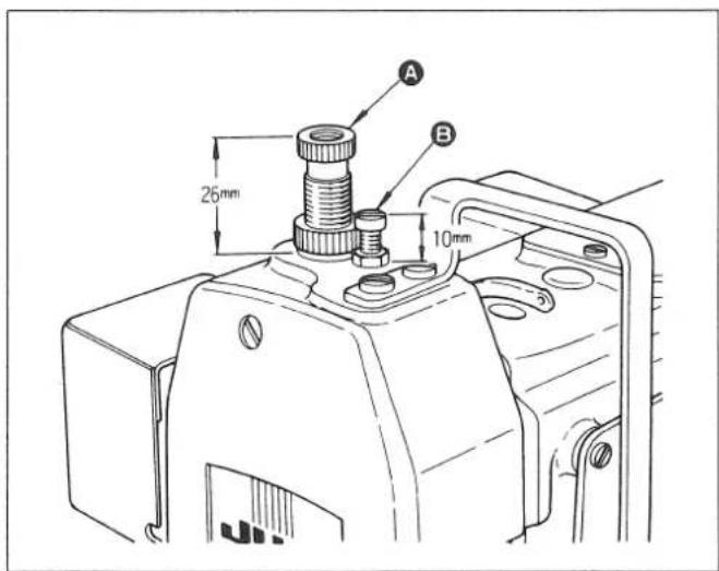
- The pressure of walking floor (height of adjustment screw A : Standard, 26 mm) or the presser foot B (height of the adjustment screw : Standard, 10 mm) can be adjusted in accordance with the type of sewing product to be used.
It is advisable to minimize the pressures of both feet.
15. HEIGHT OF THE FEED DOG (DSC-244)

WARNING :
To protect against possible personal injury due to abrupt start of the machine, be sure to start the following work after turning the power off and ascertaining that the motor is at rest.


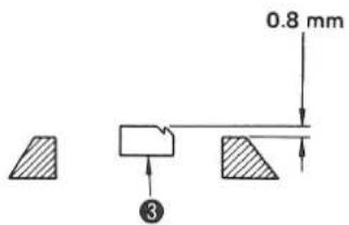
Feed dog ③ has been adjusted so that it has protruded from throat plate ① by 0.8 mm. To adjust the height of the feed dog, follow the below-stated procedure.
1) Remove throat plate ①, bed upper cover ② and spring support shaft ④ to extract feed bar ⑤.
2) Remove pin 6
3) Replace pin 6.
(Caution) 1. Marker lines are marked. When making the height of the feed dog high, use the pin having more marker lines, and when making the height low, use the pin having less marker lines.
(Note that the longest pin from among the applicable five different kinds of the pin is supplied with the machine in the accessory box.)
| Part No. | B163224500A | B163224500B | B163224500C(Standard) | B163224500D | B163224500E |
| Length (mm) | 5.7 ± 0.05 | 5.9 ± 0.05 | 6.1 ± 0.05 | 6.3 ± 0.05 | 6.5 ± 0.05 |
| Number of marker lines | 1 | 2 | 3 | 4 | 5 |
16. ADJUSTING THE WALKING FOOT AND THE PRESSER FOOT

WARNING :
To protect against possible personal injury due to abrupt start of the machine, be sure to start the following work after turning the power off and ascertaining that the motor is at rest.
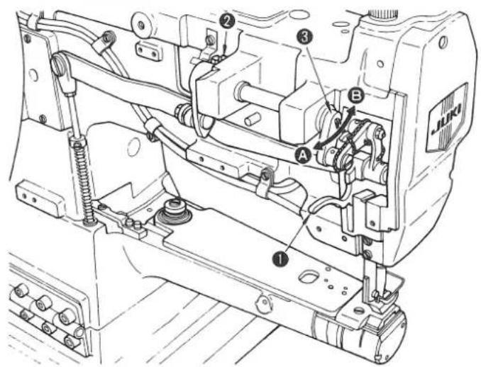
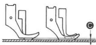

- The amount of alternating vertical motions of the walking foot and the presser foot
- The alternate vertical strokes of the walking foot and the presser foot have been adjusted to be equal.
- Depending on the type of material to be sewing, however, the vertical strokes of the presser foot and walking foot should be changed for better feeding performance.
- For instance, when sewing a slippery material or sewing a material which has many overlapping sections a better result may be obtained by adjusting the vertical stroke of the walking foot larger than that of the presser foot.
1) Remove the walking foot cover (front), and turn the handwheel by hand until the thread take-up reaches its lowest point.
2) Lower hand lifter ①.
3) Loosen screw ②.
4) As you move to feed crank ③ to the left (in direction A), the vertical stroke of the presser foot decreases D, whereas the vertical stroke of the walking foot increases E.
5) On the contrary, as you move the top feed crank to the right (in direction B), the vertical stroke of the walking foot comes almost equal C to that of the presser foot when bottom face of the walking foot is in contact with the throat plate surface.
6) After adjustment, securely tighten screw ②.
7) Reinstall the walking foot cover (front).

- Operating height of the walking foot and the presser foot
When sewing an elastic material or a material which has many overlapping sections, a better result may be obtained by changing the operating height of the walking foot and presser foot.
1) Loosen nut ①
2) When you move the cam rod boss toward Ⓐ within the slot, the height is increased.
3) When you move it toward Ⓑ, the height is decreased
4) After adjustment, securely tighten nut ①.

- Adjusting the longitudinal position of the needle bar frame
- Turn the feed regulator dial to maximum.
- Loosen feed rocker (arm) clamping screw ① and adjust so that the feed dog does not come in contact with the front and rear ends of the groove in the throat plate when the handwheel is slowly turned toward you to make the machine run in the normal feed direction or in the reverse feed direction.

-
Next, turn the feed regulator dial clockwise, set the feed pitch at "0" and loosen screw ② in the rear arm of the needle bar farme.
-
Turn the handwheel to make the needle bar frame move to allow the needle to enter the center of the needle hole in the throat plate. Then tighten screw ②.
17. NEEDLE-TO-HOOK RELATIONSHIP

WARNING :
To protect against possible personal injury due to abrupt start of the machine, be sure to start the following work after turning the power off and ascertaining that the motor is at rest.
- Positioning the needle bar

- Positioning the hook
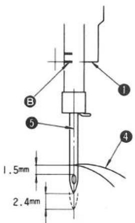
- First, set the needle bar at the proper height as follows
Set the dial to the minimum scale.
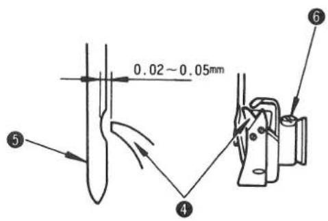
Adjust so that, when hook point ④ meets the center of needle ⑤, the hook point is 1.5 mm above the upper end of the needle eyelet. Then tighten screw ③ of needle bar bracket ②. (As a rough indication of this adjustment, marker line A on the needle bar aligns with the bottom face of the needle bar frame when the needle is in the lowest position of its stroke.)
- Then, adjust the timing between the needle and the hook as follows:
Adjust so that blade point ④ of the hook nearly aligns with the center of needle ⑤ and that the clearance of 0.02 to 0.05 mm is provided between needle ⑤ and blade point ④ of the hook when the needle bar ascends from the lowest position of its stroke by 2.4 mm. Then tighten screw ⑥ in the hook. (As a rough indication of this adjustment, maker line B on the needle bar aligns with the bottom face of the needle bar frame.)
★ How to remove the hook
- Turn the handwheel to bring the needle bar up to its highest position.
- Remove the hook cover, the bobbin case, the throat plate and the top cover of the bed.
- Loosen four screws ⑦ in the throat plate frame.
- Loosen the hook setscrew, and extract the hook so as to lift the front edge of the throat plate frame.
(Note) When installing the hook, tighten the throat plate frame after checking that the protruding portion of the hook stopper in the throat plate frame are properly inserted in the slot in the bobbin case retainer.

18. HOW TO CHANGE FROM ELLIPTICAL FEED TO HORIZONTAL FEED

WARNING :
To protect against possible personal injury due to abrupt start of the machine, be sure to start the following work after turning the power off and ascertaining that the motor is at rest.
This model can be changed to horizontal feed suitable for attaching tapes by replacing parts.
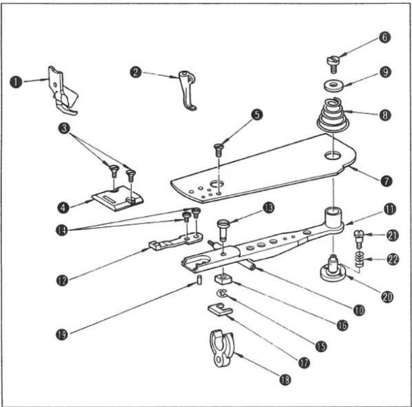
1. Removing process
1) Remove presser foot (asm.) ① and walking foot ②.
2) Loosen throat plate setscrew ③ and remove throat plate ④.
3) Loosen setscrew ⑤ and cap screw ⑥, and remove bed top cover ⑦, bed top cover spring ⑧ and feed bar hinge stud cap ⑨.
4) Remove spring support shaft 10.
5) Remove feed bar 11. (At this time, remove it with feed 12 and feed bar hinge stud 13, etc. mounted.)
6) Remove setscrew 14 to remove feed 12 from feed bar 11.
7) Remove E ring 15, and remove feed bar block B 16 from feed bar hinge stud 13.
8) Loosen feed bar hinge stud ⑬ and remove it from feed bar ⑪.
9) Remove feed bar block A from feed bar rocker arm 18 . (it is unnecessary to remove 18 .)
10) Remove upper/lower feed pin ⑲.
11) Remove feed bar hinge stud 20, screw 21 and spring 22.
List of parts to be removed
| Note | No. | Part No. | Part Name | Q'ty | Remarks |
| 1 | B15242450A0 | Presser foot (asm.) | 1 | ||
| 2 | B1470245000 | Walking foot | 1 | ||
| 3 | SS2110915SP | Throat plate setscrew | 2 | 11/64 threads 40, L=8.5 | |
| 4 | B1105245000 | Throat plate | 1 | ||
| 5 | SS2090710SP | Bed top cover setscrew | 1 | 9/64 threads 40, L=7 | |
| * | 6 | B1653245000 | Feed bar cap screw | 1 | 9/64 threads 40, L=10 |
| 7 | B1173245000 | Bed top cover | 1 | ||
| 8 | B1175245000 | Bed top cover spring | 1 | ||
| * | 9 | B1640245000 | Feed bar hinge stud cap | 1 | |
| * | 10 | B1638245000 | Spring support shaft | 1 | |
| * | 11 | B1606245000 | Feed bar | 1 | |
| 12 | B1613245000 | Feed | 1 | ||
| 13 | B1645245000 | Feed bar block hinge stud | 1 | ||
| * | 14 | B1652245000 | Feed bar setscrew | 2 | 1/8 threads 44, L=3.7 |
| 15 | RE0300000K0 | E ring | 1 | ||
| 16 | B1644245000 | Feed bar block B | 1 | ||
| 17 | B1643245000 | Feed bar block A | 1 | ||
| * | 18 | B1603245000 | Feed bar rocker arm | 1 | |
| 19 | B163224500C | Upper/lower feed pin | 1 | ||
| * | 20 | B1639245000 | Feed bar hinge stud | 1 | |
| 21 | B1641245000 | Feed bar hinge stud screw | 2 | ||
| 22 | B1642245000 | Feed bar hinge stud screw spring | 2 |
(Caution) marks mean the parts used succeedingly after replacement.

2. Installation process
1) Fix feed bar hinge stud 20 to bed top cover 26 using feed bar hinge stud set-screw 36.
2) Install feed bar block ②3 on feed bar rocker arm ⑯.
3) Install feed bar block hinge stud ②4 on feed bar ⑪.
4) Temporarily install feed ②5 on feed bar ⑪.
5) Install feed bar ⑪ on which feed bar block hinge stud ②4 and feed ⑤ have been mounted.
6) Install spring support shaft 10.
7) Tighten feed ②5 so that the needle locates in the center of needle hole.
8) Screw binder setscrew 27 into bed top cover 26. At this time, install binder setscrew 27 after applying adhesive to it.
9) Screw binder lock nut 28 into binder setscrew 27.
10) Install tape guide 29 on bed top cover 26 by tape guide setscrew 30.
11) After performing 8), 9) and 10), install bed top cover 26.
12) After installing bed top cover spring 31 and feed bar hinge stud cap 9, tighten feed bar hinge stud cap screw 6.
13) Install throat plate ③2 and fix it by throat setscrew ③3.
14) Presser foot (asm.) ③4 and walking foot ③5
List of parts to be replaced
| Note | No. | Part No. | Part Name | Q'ty | Remarks |
| 23 | MAQ09210000 | Feed bar block | 1 | ||
| 24 | MAQ09211000 | Feed bar block shaft | 1 | ||
| 25 | MAN10451000 | Feed unit | 1 | ||
| 26 | MAQ09202000 | Top cover of bed | 1 | ||
| 27 | MAQ09204000 | Screw in binder | 2 | 11/64 thread 40 | |
| 28 | MAQ09205000 | Nut of screw in binder | 2 | 11/64 thread 40 | |
| 29 | MAQ09206000 | Tape guide | 1 | ||
| 30 | SS7110510SP | Screw in tape guide | 1 | 11/64 thread 40, L=5 | |
| 31 | MAQ09203000 | Spring of top cover of bed | 1 | ||
| 32 | MAQ09201000 | Throat plate | 1 | ||
| 33 | SS2110930SP | Screw in throat plate | 2 | 11/64 thread 40, L=8.5 | |
| 34 | MAQ093080A0 | Presser foot (asm.) | 1 | ||
| 35 | MAN10452000 | Walking foot | 1 | ||
| 36 | SS7110910SP | Feed bar hinge stud screw | 2 |
19. HOW TO CHANGE FROM HORIZONTAL FEED TO ELLIPTICAL FEED

WARNING :
To protect against possible personal injury due to abrupt start of the machine, be sure to start the following work after turning the power off and ascertaining that the motor is at rest.
This model can be changed to elliptical feed by changing the related parts accordingly.

1. Removing process
1) Remove presser foot (asm.) ⑫ and walking foot ⑬.
2) Loosen throat plate setscrew ⑪ and remove throat plate ⑩.
3) Loosen screw 14 in the feed bar shaft cover, and remove top cover 4 of the bed, top cover spring 9 of the bed and cover 15 of feed bar shaft.
4) Remove the feed unit with tape guide ⑦, screw ⑧ in the tape guide, screws ⑤ in the binder and nuts ⑥ of the screws in the binder attached on top cover ④ of the bed.
5) Remove spring support shaft 16.
6) Remove feed bar ⑰. (At this time, it should be removed with feed ③, feed bar block shaft ② attached in place.)
7) Remove feed bar block 1 from feed bar oscillating arm 19.
8) Remove feed bar block shaft ② from feed bar ⑰.
9) Loosen screws 18 in the feed, and remove feed 3.
10) Remove feed bar stud 20, screw 21.
List of parts to be removed
| Note | No. | Part No. | Part Name | Q'ty | Remarks |
| 1 | MAQ09210000 | Feed bar block | 1 | ||
| 2 | MAQ09211000 | Feed bar block shaft | 1 | ||
| 3 | MAN10451000 | Feed | 1 | ||
| 4 | MAQ09202000 | Top cover of bed | 1 | ||
| 5 | MAQ09204000 | Screw in binder | 2 | 11/64 40 thread ridges | |
| 6 | MAQ09205000 | Nut of screw in binder | 2 | 11/64 40 thread ridges | |
| 7 | MAQ09206000 | Tape guide | 1 | ||
| 8 | SS7110510SP | Screw in tape guide | 1 | 11/64 40 thread ridges, L = 5 | |
| 9 | MAQ09203000 | Spring of top cover of bed | 1 | ||
| 10 | MAQ09201000 | Throat plate | 1 | ||
| 11 | SS2110930SP | Screw in throat plate | 2 | 11/64 40 thread ridges, L = 8.5 | |
| 12 | MAQ093080A0 | Presser foot (asm.) | 1 | ||
| 13 | MAQ09307000 | Walking foot | 1 | ||
| ★ | 14 | B1653245000 | Screw in the feed bar shaft cover | 1 | 9/64 40 thread ridges, L = 10 |
| ★ | 15 | B1640245000 | Cover of feed bar shaft | 1 | |
| ★ | 16 | B1638245000 | Spring support shaft | 1 | |
| ★ | 17 | B1606245E00 | Feed bar | 1 | |
| D1606245E00 | Feed bar | 1 | |||
| ★ | 18 | B1652245000 | Screw in feed | 2 | 1/8 44 thread ridges, L = 3.7 |
| ★ | 19 | B1603245000 | Feed bar oscillating arm | 1 | |
| ★ | 20 | B1639245000 | Feed bar hinge stud | 1 | |
| 21 | SS7110910SP | Feed bar hinge stud screw | 2 |
(Caution)
★ marks mean the parts used succeedingly after replacement.
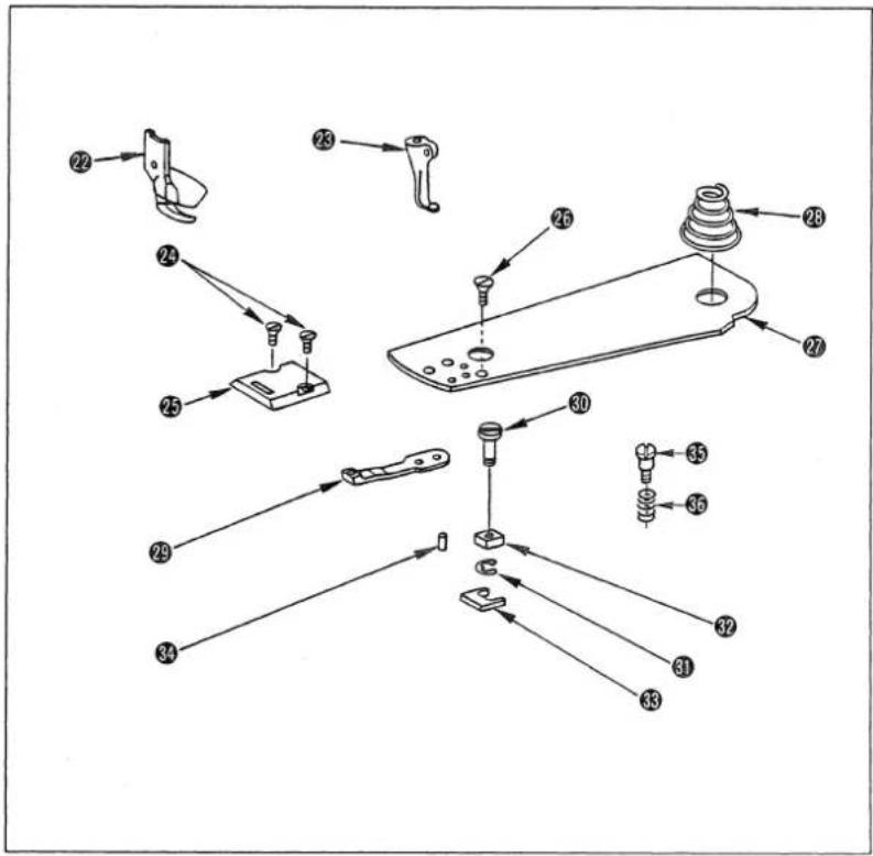
2. Installation procedure
1) Fit spring 36 over screw 35. In this state, fix feed bar hinge stud.
2) Attach feed driving pin 34 in place.
3) Attach feed bar block A ③ on feed bar oscillating arm ⑲.
4) Attach feed bar block shaft ③0 on feed bar ⑰.
5) Attach feed bar block B 32 in feed bar block shaft 30 using E ring 31.
6) Attach feed 29 on feed bar 17
7) Attach feed bar block shaft 30 and feed bar 17 on which feed 29 has been attached in place.
8) Install spring support shaft 16 in place.
9) Tighten feed 29 to allow the needle to come just at the center of the needle hole in the feed.
10) Top cover spring 28 of the bed, feed bar shaft cover 15 and screw 14 of the feed bar shaft cover 15 in place.
11) Fix top cover 27 of the bed by tightening screw 26 in the top cover of the bed.
12) Attach throat plate ②5 in place and fix it using screw ②4 of the throat plate.
13) Install presser foot (asm.) ② and walking foot ③ in place.
List of parts to be replaced
| Note | No. | Part No. | Part Name | Q'ty | Remarks |
| 22 | B15242450A0 | Presser foot (asm.) | 1 | ||
| 23 | B1470245000 | Walking foot | 1 | ||
| 24 | SS2110915SP | Screw in throat plate | 2 | 11/64 40 thread ridges, L=8.5 | |
| 25 | B1105245000 | Throat plate | 1 | ||
| 26 | SS2090710SP | Screw in top cover of bed | 1 | 9/64 40 thread ridges, L=7 | |
| 27 | B1173245000 | Top cover of bed | 1 | ||
| 28 | B1175245000 | Spring of top cover of bed | 1 | ||
| 29 | B1613245000 | Feed | 1 | ||
| 30 | B1645245000 | Feed bar block | 1 | ||
| 31 | RE0300000K0 | E ring | 1 | ||
| 32 | B1644245000 | Feed bar block B | 1 | ||
| 33 | B1643145000 | Feed bar block A | 1 | ||
| 34 | B163214500G | Feed driving pin | 1 | ||
| 35 | B1641245000 | Feed bar hinge stud screw | 2 | ||
| 36 | B1642245000 | Feed bar hinge stud screw spring | 2 |
(Caution) The feed driving pin has engraved marker lines. Use the pin which has many marker lines to raise the feed dog, or use the pin with less marker lines to lower it.
| Part No. | B163224500A | B163224500B | B163224500C(Standard) | B163224500D | B163224500E |
| Length (mm) | 5.7 ± 0.05 | 5.9 ± 0.05 | 6.1 ± 0.05 | 6.3 ± 0.05 | 6.5 ± 0.05 |
| Number of marker lines | 1 | 2 | 3 | 4 | 5 |
20. MOTOR PULLEY AND SEWING SPEED
- Use the 3-phase 400 W AC clutch motor.
- Use an M type V belt.
- The following table shows the relationship among the motor pulley and the sewing speed.
| Model Sewing speed Effective | diameter ofhandwheel | Numberof poles | Frequency Rotationalspeed ofmotor | Effective diameter ofmotor pulley | |
| DSC-244DSC-244V | 2,200 sti/min φ 76.0 4 | 50Hz 1430rpm φ 115 | |||
| 60Hz 1715rpm φ 95 | |||||
(Caution) The effective diameter of the motor pulley is obtained by subtracting 5 mm from the outside diameter.
- TROUBLES AND CORRECTIVE MEASURES
| Trouble | Cause | Corrective measures |
| 1. Thread breakage (Thread frays or wears out.) (Needle thread remains 2 to 3 cm on the wrong side of the cloth.) | 1 The thread path, needle point, hook point or bobbin case positioning finger has scratches.2 The needle thread tension is too high.3 The needle hits the hook point.4 The needle thread tension is too low.5 The thread take-up spring has an excessively high tension while it has an excessively small stroke.6 The timing between the needle and hook is too early or late.7 The bobbin races frequently. | Remove the scratches on the hook point using a fine sand paper. Buff the bobbin case positioning finger.Properly adjust the needle thread tension.See “17. NEEDLE-TO-HOOK RELATIONSHIP”.Properly adjust the needle thread tension.Decrease the tension, and increase the stroke.See “17. NEEDLE-TO-HOOK RELATIONSHIP”.Increase the idling prevention spring pressure. |
| 2. Stitch skipping | 1 The clearance between the needle and the hook point is too large.2 The timing between the needle and the hook point is too early or late.3 The presser foot pressure is too low.4 The clearance between the top edge of the needle eyelet and the hook point is not correct.5 The size of the needle is wrong.6 A synthetic fiber thread or thin thread is used. | See “17. NEEDLE-TO-HOOK RELATIONSHIP”.See “17. NEEDLE-TO-HOOK RELATIONSHIP”.Increase the presser foot pressure.See “17. NEEDLE-TO-HOOK RELATIONSHIP”.Replace the needle by one which is one grade thicker.Wind the thread round the needle as illustrated.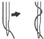 |
| 3. Loose stitches | 1 The thread has not been passed through the notch of the bobbin case tension spring.2 The presser foot or the thread path of the needle hole in the feed dog are poorly finished.3 The bobbin does not rotate smoothly.4 The bobbin thread tension is too low.5 The bobbin thread has been wound too tight.6 An untwisted synthetic thread is used.7 A coated cloth or nylon yarn is used. | Properly thread the bobbin case.Grind it using a fine sand paper or a buff.Replace the bobbin or the bobbin case.Too high the tension of the bobbin thread tension.Decrease the tension of the bobbin thread winding tension.Slightly reduce the sewing speed.(2,000sti/min)Use a ball-point needle. |
| 4. Chain off thread doesn't come out | 1 Breakage between the bottom face of the presser foot and the contact face with throat plate. | Use B1524-245-0AA presser foot (option). |
| 5. Stepped part is clogged. | 1 The presser foot slips when riding on the stepped part.2 The alternating vertical strokes of the walking foot and the presser foot are too small. | Use B1524-245-0AB presser foot (asm.) (option) and B1470-245-00B walking foot (option).See “16. Adjusting the walking foot and the presser foot”. |
| 6. When the alternate lift is increased, the pitch cannot be achieved as per the scale. | 1 Sewing speed is too fast, resulting in reducing the feed force. | Reduce the sewing speed. |
The item attached with an asterisk (*) applies to the DSC-244.

JUKI CORPORATION
SEWING MACHINERY BUSINESS UNIT
2-11-1, TSURUMAKI, TAMA-SHI,
Copyright © 2011-2013 JUKI CORPORATION
- All rights reserved throughout the world.
Please do not hesitate to contact our distributors or agents in your area for further information when necessary.
* The description covered in this instruction manual is subject to change for improvement of the commodity without notice.


- TO ENSURE SAFE USE OF YOUR SEWING MACHINE
- EXPLANATION OF RISK LEVELS
- EXPLANATION OF PICTORIAL WARNING INDICATIONS AND WARNING LABELS
- DANGER
- CAUTION
- BASIC PRECAUTION
- SAFETY DEVICES AND WARNING LABELS
- APPLICATION AND MODIFICATION
- EDUCATION AND TRAINING
- ITEMS FOR WHICH THE POWER TO THE MACHINE HAS TO BE TURNED OFF
- PRECAUTIONS TO BE TAKEN IN VARIOUS OPERATION STAGES
- TRANSPORTATION
- UNPACKING
- INSTALLATION
- TABLE AND TABLE STAND
- CABLE AND WIRING
- GROUNDING
- MOTOR
- BEFORE OPERATION
- DURING OPERATION
- LUBRICATION
- MAINTENANCE
- OPERATING ENVIRONMENT
- FOR SAFE OPERATION
- DECLARATION OF INCORPORATION OF PARTLY COMPLETED MACHINERY
- CONTENTS
- SPECIFICATIONS....1
- SPECIFICATIONS
- SETTING UP THE SEWING MACHINE
- INSTALLING THE THREAD STAND
- INSTALLING THE BELT COVER AND THE BOBBIN WINDER
- WARNING
- BEFORE STARTING THE SEWING MACHINE
- LUBRICATING THE HOOK
- ATTACHING THE NEEDLE
- TURN THE MOTOR POWER OFF
- WINDING A BOBBIN
- THREADING THE BOBBIN CASE
- REMOVING THE BOBBIN CASE
- INSTALLING THE TAKE-UP THREAD GUIDE ROD
- THREAD THE MACHINE HEAD
- ADJUSTING THE STITCH LENGTH
- FORWARD/REVERSE SEAM RATIO
- THREAD TENSION
- THREAD TAKE-UP SPRING
- PRESSURES OF THE PRESSER FOOT AND WALKING FOOT
- HEIGHT OF THE FEED DOG (DSC-244)
- ADJUSTING THE WALKING FOOT AND THE PRESSER FOOT
- NEEDLE-TO-HOOK RELATIONSHIP
- HOW TO CHANGE FROM ELLIPTICAL FEED TO HORIZONTAL FEED
- REMOVING PROCESS
- INSTALLATION PROCESS
- HOW TO CHANGE FROM HORIZONTAL FEED TO ELLIPTICAL FEED
- INSTALLATION PROCEDURE
- MOTOR PULLEY AND SEWING SPEED
- JUKI CORPORATION
Brand : JUKI
Model : DSC-244
Category : Sewing machine