
MF3620 - Sewing machine JUKI - Free user manual and instructions
Find the device manual for free MF3620 JUKI in PDF.
| Brand | Juki |
| Model | MF3620 |
| Type | 4-needle coverstitch sewing machine (overlock), offset arm |
| Width | 290 mm |
| Depth | 414 mm (belt version) / 560 mm (direct drive version) |
| Height | 426 mm |
| Head weight | 22.5 kg (belt version) / 26.5 kg (direct drive version) |
| Maximum sewing speed | 4,200 stitches/min (normal), limited to 3,200 stitches/min during break-in |
| Stitch type | JIS F46 (US-607), coverstitch |
| Needle gauge | 5.2 mm or 6.0 mm |
| Needle bar stroke | 30 mm |
| Compatible needles | FLx118GCS (size #9 to #12) for main needles, FLG-8 for retainer needle |
| Presser foot lift height | 6.5 mm (with micro-lifter) |
| Stitch length | 1.6 to 2.5 mm (adjustable) |
| Differential feed | Adjustable by lever |
| Lubrication system | Automatic by gear pump |
| Lubricating oil | Juki New Defrix Oil No.2 |
| Front oil tank capacity | 70 to 80 ml |
| Rear oil tank capacity | 60 to 70 ml |
| Noise (sound pressure level) | 80 dB(A) at 3,200 stitches/min (according to ISO 10821) |
| Power supply | Single-phase or three-phase depending on motor, voltage ±10% of nominal |
| Operating ambient temperature | 5 to 35 °C |
| Operating relative humidity | 35 to 85% |
| Included accessories | Auxiliary table, belt cover, thread guide, thread stand, chain cutter |
Frequently Asked Questions - MF3620 JUKI
User questions about MF3620 JUKI
0 question about this device. Answer the ones you know or ask your own.
Ask a new question about this device
Download the instructions for your Sewing machine in PDF format for free! Find your manual MF3620 - JUKI and take your electronic device back in hand. On this page are published all the documents necessary for the use of your device. MF3620 by JUKI.
USER MANUAL MF3620 JUKI
natural_image
Technical line drawing of a sewing machine (no text or symbols visible)| 注意:このたびは、当社の製品をお買い上げいただきましてありがとうございました。安全に使用していただくために、使用前に必ずこの取扱説明書をお読みください。また、いつでもすぐに読めるように、この取扱説明書を保管してください。 |
| NOTE:Read safety instructions carefully and understand them before using.Retain this Instruction Manual for future reference. |
| HINWEIS:Lesen Sie die Sicherheitsanweisungen aufmerksam durch, um sich mit ihnen vertraut zu machen, bevor Sie diese Maschine in Betrieb nehmen. Bewahren Sie diese Bedienungsanleitung für spätere Bezugnahme auf. |
| NOTE:Avant d’utiliser la machine, lire attentivement toutes les consignes de sécurité.Conserver ce manuel pour pouvior le consulter en cas de besoin. |
| NOTA:Antes de comenzar a usar esta máquina lea con detención hasta comprender todas las instruccione de seguridad. Conserve este Manual de instrucciones a mano para futuras consultas. |
| NOTA:Leggere attentamente e compredere tutte le istruzioni per la sicurezza prima di inziare l’uso di questa macchina. Conservare questo Manuale d’Instruzioni per pronto riferimento. |
| 注意:为了安全地使用,请您在使用之前一定阅读本使用说明书。另外,请您注意保管本使用说明书,以便随时查阅。 |
| NOT:Güvenlik talimatını dikkatle okuyun ve makineyi kullanmadan önce tümüyle öğrenin.Gelecekte de yararlanmak için, bu kullanma kılavuzunu muhafaza edin. |
| ЗАМЕЧАНИЯ:Внимательно прочитайте и усвойте правила техники безопасности перед использованием швейной машины. Сохраните эту инструкцию по эксплуатации для того, чтобы обращаться к ней и в будущем |
安全にご使用していただくために
TO ENSURE SAFE USE OF YOUR SEWING MACHINE
For the sewing machine, automatic machine and ancillary devices (hereinafter collectively referred to as "machine"), it is inevitable to conduct sewing work near moving parts of the machine. This means that there is always a possibility of unintentionally coming in contact with the moving parts. Operators who actually operate the machine and maintenance personnel who are involved in maintenance and repair of the machine are strongly recommended to carefully read to fully understand the following SAFETY PRECAUTIONS before using/maintaining the machine. The content of the SAFETY PRECAUTIONS includes items which are not contained in the specifications of your product.
The risk indications are classified into the following three different categories to help understand the meaning of the labels. Be sure to fully understand the following description and strictly observe the instructions.
( I ) Explanation of risk levels
 | DANGER:This indication is given where there is an immediate danger of death or serous injury if the person in charge or any third party mishandles the machine or does not avoid the dangerous situation when operating or maintaining the machine. |
 | WARNING:This indication is given where there is a potentiality for death or serious injury if the person in charge or any third party mishandles the machine or does not avoid the dangerous situation when operating or maintaining the machine. |
 | CAUTION:This indication is given where there is a danger of medium to minor injury if the person in charge or any third party mishandles the machine or does not avoid the dangerous situation when operating or maintaining the machine. |
 | Items requiring special attention. |
(II) Explanation of pictorial warning indications and warning labels
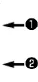
| Pictorial warning indication |  | There is a risk of injury if contacting a moving section. | Pictorial warning indication | Be aware that holding the sewing machine during operation can hurt your hands. | |
 | There is a risk of electrical shock if contacting a high-voltage section. | There is a risk of entanglement in the belt resulting in injury. | |||
 | There is a risk of a burn if contacting a high-temperature section. | There is a risk of injury if you touch the button carrier. | |||
 | Be aware that eye deficiency can be caused by looking directly at the laser beam. | Indication label | The correct direction is indicated. | ||
 | There is a risk of contact between your head and the sewing machine. | Connection of a earth cable is indicated. |
| Warning label | 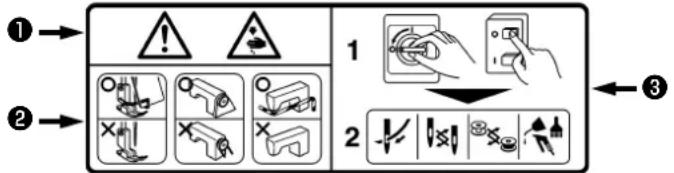 1·There is the possibility that slight to serious injury or death may be caused.2·There is the possibility that injury may be caused by touching moving part.3·To perform sewing work with safety guard.4·To perform sewing work with safety cover.5·To perform sewing work with safety protection device.6·Be sure to turn the power OFF before carrying out "machine-head threading", "needle changing", "bobbin changing" or "oiling and cleaning". 1·There is the possibility that slight to serious injury or death may be caused.2·There is the possibility that injury may be caused by touching moving part.3·To perform sewing work with safety guard.4·To perform sewing work with safety cover.5·To perform sewing work with safety protection device.6·Be sure to turn the power OFF before carrying out "machine-head threading", "needle changing", "bobbin changing" or "oiling and cleaning". | 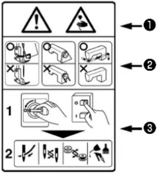 |
| Electrical-shock danger label |  |

DANGER
- When it is necessary to open the control box containing electrical parts, be sure to turn the power off and wait for five minutes or more before opening the cover in order to prevent accident leading to electrical shock.

CAUTION
Basic precaution
- Be sure to read the instruction manual and other explanatory documents supplied with accessories of the machine before using the machine. Carefully keep the instruction manual and the explanatory documents at hand for quick reference.
- The content of this section includes items which are not contained in the specifications of your product.
- Be sure to wear safety goggles to protect against accident caused by needle breakage.
- Those who use a heart pacer have to use the machine after consultation with a medical specialist.
Safety devices and warning labels
- Be sure to operate the machine after verifying that safety device(s) is correctly installed in place and works normally in order to prevent accident caused by lack of the device(s).
- If any of the safety devices is removed, be sure to replace it and verify that it works normally in order to prevent accident that can result in personal injury or death.
- Be sure to keep the warning labels adhered on the machine clearly visible in order to prevent accident that can result in personal injury or death. If any of the labels has stained or come unstuck, be sure to change it with a new one.
Application and modification
- Never use the machine for any application other than its intended one and in any manner other than that prescribed in the instruction manual in order to prevent accident that can result in personal injury or death. JUKI assumes no responsibility for damages or personal injury or death resulting from the use of the machine for any application other than the intended one.
- Never modify and alter the machine in order to prevent accident that can result in personal injury or death. JUKI assumes no responsibility for damages or personal injury or death resulting from the machine which has been modified or altered.
Education and training
- In order to prevent accident resulting from unfamiliarity with the machine, the machine has to be used only by the operator who has been trained/educated by the employer with respect to the machine operation and how to operate the machine with safety to acquire adequate knowledge and operation skill. To ensure the above, the employer has to establish an education/training plan for the operators and educate/train them beforehand.
Items for which the power to the machine has to be turned off
Turning the power off: Turning the power switch off, then removing the power plug from the outlet. This applies to the following.
- Be sure to immediately turn the power off if any abnormality or failure is found or in the case of power failure in order to protect against accident that can result in personal injury or death.
- To protect against accident resulting from abrupt start of the machine, be sure to carry out the following operations after turning the power off. For the machine incorporating a clutch motor, in particular, be sure to carry out the following operations after turning the power off and verifying that the machine stops completely.
2-1. For example, threading the parts such as the needle, looper, spreader etc. which have to be threaded, or changing the bobbin.
2-2. For example, changing or adjusting all component parts of the machine.
2-3. For example, when inspecting, repairing or cleaning the machine or leaving the machine. - Be sure to remove the power plug by holding the plug section instead of the cord section in order to prevent electrical-shock, earth-leakage or fire accident.
- Be sure to turn the power off whenever the machine is left unattended between works.
- Be sure to turn the power off in the case of power failure in order to prevent accident resulting of breakage of electrical components.
PRECAUTIONS TO BE TAKEN IN VARIOUS OPERATION STAGES
Transportation
- Be sure to lift and move the machine in a safe manner taking the machine weight in consideration. Refer to the text of the instruction manual for the mass of the machine.
- Be sure to take sufficient safety measures to prevent falling or dropping before lifting or moving the machine in order to protect against accident that can result in personal injury or death.
- Once the machine has been unpacked, never re-pack it for transportation to protect the machine against breakage resulting from unexpected accident or dropping.
Unpacking
- Be sure to unpack the machine in the prescribed order in order to prevent accident that can result in personal injury or death. In the case the machine is crated, in particular, be sure to carefully check nails. The nails have to be removed.
- Be sure to check the machine for the position of its center of gravity and take it out from the package carefully in order to prevent accident that can result in personal injury or death.
Installation
(I) Table and table stand
- Be sure to use JUKI genuine table and table stand in order to prevent accident that can result in personal injury or death. If it is inevitable to use a table and table stand which are not JUKI genuine ones, select the table and table stand which are able to support the machine weight and reaction force during operation.
- If casters are fitted to the table stand, be sure to use the casters with a locking mechanism and lock them to secure the machine during the operation, maintenance, inspection and repair in order to prevent accident that can result in personal injury or death.
(II) Cable and wiring
- Be sure to prevent an extra force from being applied to the cable during the use in order to prevent electrical-shock, earth-leakage or fire accident. In addition, if it is necessary to cable near the operating section such as the V-belt, be sure to provide a space of 30 mm or more between the operating section and the cable.
- Be sure to avoid starburst connection in order to prevent electrical-shock, earth-leakage or fire accident.
- Be sure to securely connect the connectors in order to prevent electrical-shock, earth-leakage or fire accident. In addition, be sure to remove the connector while holding its connector section.
(III) Grounding
- Be sure to have an electrical expert install an appropriate power plug in order to prevent accident caused by earth-leakage or dielectric strength voltage fault. In addition, be sure to connect the power plug to the grounded outlet without exceptions.
- Be sure to ground the earth cable in order to prevent accident caused by earth leakage.
(IV) Motor
- Be sure to use the specified rated motor (JUKI genuine product) in order to prevent accident caused by burnout.
- If a commercially available clutch motor is used with the machine, be sure to select one with an entanglement preventive pulley cover in order to protect against being entangled by the V-belt.
Before operation
- Be sure to make sure that the connectors and cables are free from damage, dropout and looseness before turning the power on in order to prevent accident resulting in personal injury or death.
- Never put your hand into the moving sections of the machine in order to prevent accident that can result in personal injury or death. In addition, check to be sure that the direction of rotation of the pulley agrees with the arrow shown on pulley.
- If the table stand with casters is used, be sure to secure the table stand by locking the casters or with adjusters, if provided, in order to protect against accident caused by abrupt start of the machine.
During operation
- Be sure not to put your fingers, hair or clothing close to the moving sections such as the handwheel, hand pulley and motor or place something near those sections while the machine is in operation in order to prevent accident caused by entanglement that can result in personal injury or death.
- Be sure not to place your fingers near the surround area of the needle or inside the thread take-up lever cover when turning the power on or while the machine is in operation in order to prevent accident that can result in personal injury or death.
- The machine runs at a high speed. Never bring your hands near the moving sections such as looper, spreader, needle bar, hook and cloth trimming knife during operation in order to protect your hands against injury. In addition, be sure to turn the power off and check to be sure that the machine completely stops before changing the thread.
-
Be careful not to allow your fingers or any other parts of your body to be caught between the machine and table when removing the machine from or replacing it on the table in order to prevent accident that can result in personal injury or death.
-
Be sure to turn the power off and check to be sure that the machine and motor completely stop before removing the belt cover and V-belt in order to prevent accident caused by abrupt start of the machine or motor.
- If a servomotor is used with the machine, the motor does not produce noise while the machine is at rest. Be sure not to forget to turn the power off in order to prevent accident caused by abrupt start of the motor.
- Never use the machine with the cooling opening of the motor power box shielded in order to prevent fire accident by overheat.
Lubrication
- Be sure to use JUKI genuine oil and JUKI genuine grease to the parts to be lubricated.
- If the oil adheres on your eye or body, be sure to immediately wash it off in order to prevent inflammation or irritation.
- If the oil is swallowed unintentionally, be sure to immediately consult a medical doctor in order to prevent diarrhea or vomiting.
Maintenance
- In prevention of accident caused by unfamiliarity with the machine, repair and adjustment has to be carried out by a service technician who is thoroughly familiar with the machine within the scope defined in the instruction manual. Be sure to use JUKI genuine parts when replacing any of the machine parts. JUKI assumes no responsibility for any accident caused by improper repair or adjustment or the use of any part other than JUKI genuine one.
- In prevention of accident caused by unfamiliarity with the machine or electrical-shock accident, be sure to ask an electrical technician of your company or JUKI or distributor in your area for repair and maintenance (including wiring) of electrical components.
- When carrying out repair or maintenance of the machine which uses air-driven parts such as an air cylinder, be sure to remove the air supply pipe to expel air remaining in the machine beforehand, in order to prevent accident caused by abrupt start of the air-driven parts.
- Be sure to check that screws and nuts are free from looseness after completion of repair, adjustment and part replacement.
- Be sure to periodically clean up the machine during its duration of use. Be sure to turn the power off and verify that the machine and motor stop completely before cleaning the machine in order to prevent accident caused by abrupt start of the machine or motor.
- Be sure to turn the power off and verify that the machine and motor stop completely before carrying out maintenance, inspection or repair of the machine. (For the machine with a clutch motor, the motor will keep running for a while by inertia even after turning the power off. So, be careful.)
- If the machine cannot be normally operated after repair or adjustment, immediately stop operation and contact JUKI or the distributor in your area for repair in order to prevent accident that can result in personal injury or death.
- If the fuse has blown, be sure to turn the power off and eliminate the cause of blowing of the fuse and replace the blown fuse with a new one in order to prevent accident that can result in personal injury or death.
- Be sure to periodically clean up the air vent of the fan and inspect the area around the wiring in order to prevent fire accident of the motor.
Operating environment
- Be sure to use the machine under the environment which is not affected by strong noise source (electromagnetic waves) such as a high-frequency welder in order to prevent accident caused by malfunction of the machine.
- Never operate the machine in any place where the voltage fluctuates by more than "rated voltage ± 10% in order to prevent accident caused by malfunction of the machine.
- Be sure to verify that the air-driven device such as an air cylinder operates at the specified air pressure before using it in order to prevent accident caused by malfunction of the machine.
- To use the machine with safety, be sure to use it under the environment which satisfies the following conditions:
Ambient temperature during operation 5°C to 35°C Relative humidity during operation 35 % to 85 %
-
Dew condensation can occur if bringing the machine suddenly from a cold environment to a warm one. So, be sure to turn the power on after having waited for a sufficient period of time until there is no sign of water droplet in order to prevent accident caused by breakage or malfunction of the electrical components.
-
Be sure to stop operation when lightning flashes for the sake of safety and remove the power plug in order to prevent accident caused by breakage or malfunction of the electrical components.
-
Depending on the radio wave signal condition, the machine may generate noise in the TV or radio. If this occurs, use the TV or radio with kept well away from the machine.
-
In order to ensure the work environment, local laws and regulations in the country where the sewing machine is installed shall be followed. In the case the noise control is necessary, an ear protector or other protective gear should be worn according to the applicable laws and regulations.
-
Disposal of products and packages and treatment of used lubricating oil should be carried out properly according to the relevant laws of the country in which the sewing machine is used.
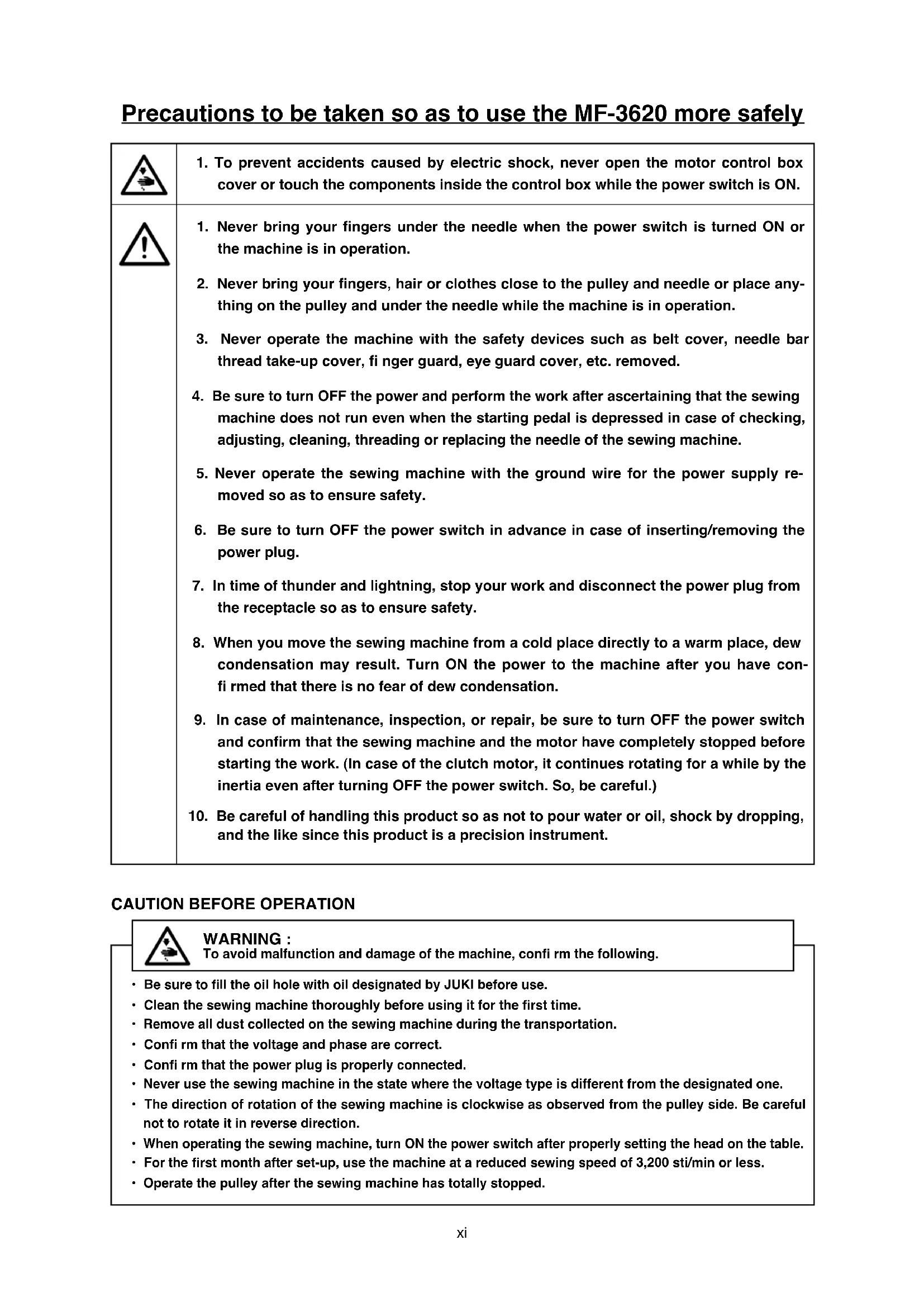
Precautions to be taken so as to use the MF-3620 more safely
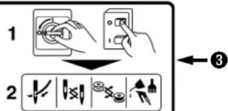
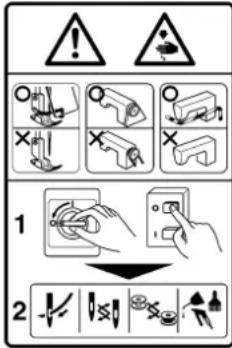
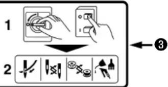
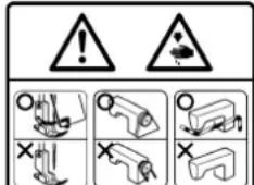
 | 1. To prevent accidents caused by electric shock, never open the motor control box cover or touch the components inside the control box while the power switch is ON. |
 | 1. Never bring your fingers under the needle when the power switch is turned ON or the machine is in operation.2. Never bring your fingers, hair or clothes close to the pulley and needle or place anything on the pulley and under the needle while the machine is in operation.3. Never operate the machine with the safety devices such as belt cover, needle bar thread take-up cover, fi nger guard, eye guard cover, etc. removed.4. Be sure to turn OFF the power and perform the work after ascertaining that the sewing machine does not run even when the starting pedal is depressed in case of checking, adjusting, cleaning, threading or replacing the needle of the sewing machine.5. Never operate the sewing machine with the ground wire for the power supply removed so as to ensure safety.6. Be sure to turn OFF the power switch in advance in case of inserting/removing the power plug.7. In time of thunder and lightning, stop your work and disconnect the power plug from the receptacle so as to ensure safety.8. When you move the sewing machine from a cold place directly to a warm place, dew condensation may result. Turn ON the power to the machine after you have confirmed that there is no fear of dew condensation.9. In case of maintenance, inspection, or repair, be sure to turn OFF the power switch and confirm that the sewing machine and the motor have completely stopped before starting the work. (In case of the clutch motor, it continues rotating for a while by the inertia even after turning OFF the power switch. So, be careful.)10. Be careful of handling this product so as not to pour water or oil, shock by dropping, and the like since this product is a precision instrument. |
To avoid malfunction and damage of the machine, confi rm the following.
- Be sure to fill the oil hole with oil designated by JUKI before use.
- Clean the sewing machine thoroughly before using it for the first time.
- Remove all dust collected on the sewing machine during the transportation.
- Confi rm that the voltage and phase are correct.
- Confirm that the power plug is properly connected.
- Never use the sewing machine in the state where the voltage type is different from the designated one.
- The direction of rotation of the sewing machine is clockwise as observed from the pulley side. Be careful not to rotate it in reverse direction.
- When operating the sewing machine, turn ON the power switch after properly setting the head on the table.
- For the first month after set-up, use the machine at a reduced sewing speed of 3,200 sti/min or less.
- Operate the pulley after the sewing machine has totally stopped.
DECLARATION OF INCORPORATION OF PARTLY COMPLETED MACHINERY
We hereby declare that the sewing machine (sewing head) described below ;
- Must not be put into service until the machinery to which it is incorporated has been declared in conformity with the provisions of the Directive 2006/42/EC, and
- Conforms to the essential requirements of the Directive 2006/42/EC, described in the technical documentation, and
- To be prepared with the above technical documentation compiled in accordance with part B of Annex VII, and
- Also to conform to the RoHS Directive 2011/65/EU
- Relevant information on which should be transmitted in response to a reasoned request by the national authorities, by the electronic method or other according to the request.
Model MF-3620
Description Industrial Sewing Machine
Function make stitches and sew
Applied harmonized standards, in particular :
EN ISO12100, EN ISO10821, EN 50581
Manufacturer :
JUKI CORPORATION
2-11-1, Tsurumaki, Tama-shi, Tokyo, Japan


| (in millions) | ||
| 2017 | 2016 | |
| Net earnings | 1,384 | 1,359 |
| Earnings per share: | ||
| (人民币元) | 0.04 | 0.04 |
| Weighted average of common stock | 0.04 | 0.04 |

PERICOLO
- Installing the sewing machine .....9
1-1. Machine head fixing base .....10
1-2. Installing the machine head .....16
1-3. How to install the belt cover for the direct-drive motor ....19
1-4. Setting the machine head .....22
-
Pulley correspondence table .....24
-
Installing the belt cover for the clutch motor....28
-
Installing the presser lifting lever .....30
-
Checking the direction of rotation .....32
-
Installing the thread guide ....32
-
Installing the thread stand ....34
-
Installing the chain-off thread cutting knife ....35
IV. LUBRICATION AND OILING .....37
-
Lubrication
-
Adding oil to the silicon container .....40
V. OPERATION ....41
-
Attaching the needle .....41
-
Threading the machine head .....43
-
Adjusting the presser foot pressure ...45
-
Adjusting the micro-lifter .....46
-
Adjusting the differential feed ratio ....47
-
Adjusting the stitch length .....48
-
Adjusting the thread tension .....50
-
Adjusting the knife pressure .....51
VI. ADJUSTING THE SEWING MACHINE ..53
-
Adjusting the height of the needle .....53
-
Replacing the presser foot ....56
-
Adjusting the covering thread carrier and covering thread hook ....66
-
Replacing/adjusting the knife .....68
-
Adjusting the height of the feed dog ..72
-
Adjusting the looper .....74
-
Adjusting the needle guard (front) .....76
-
Adjusting the needle guard (rear) .....78
-
Adjusting the needle thread guard .....79
-
Adjusting the needle thread path .....83
-
Adjusting the looper thread cam .....85
-
Adjusting the looper thread cam thread guide ....88
-
Adjusting the top covering thread path..90
-
Adjusting the top covering thread cam..92
-
Adjusting the lap former (MF-3620L2**) ..94
-
MAINTENANCE 95
-
Cleaning the sewing machine .....95
-
Replacing the lubricating oil .....97
-
Points to be applied with grease .....99
-
How to install the control box (Only for MF-3620*B)....100
INHALT
| Model name | 4-needle, feed-off-the-arm coverstitch machine for flat seam | |
| Model MF-3620 | MF-3620*B | |
| Drive method | Belt drive | Direct drive |
| Stitch type | JIS F46(US-607) | |
| Example of application Seam side of | knit and knitted fabric products, join crotch, etc. | |
| Max. sewing speed (Normal) | 4,200sti/min (3,200sti/min) | |
| Needle gauge | 5.2mm, 6.0mm | |
| Feed pitch | 1.6 to 2.5mm | |
| Applicable needle (standard count) | FL×118GCS (#9 to 12)(standard count #10S) | |
| Applicable retainer needle (standard count) | FLG-8 (standard count #8) | |
| Needle bar stroke | 30 mm | |
| Dimensions | 426 mm (height) x 290 mm (width) x 414 mm (length) | 426mm (height) x 290 mm (width) x 560mm (length) |
| Machine head weight | 22.5kg | 26.5kg |
| Lift of presser foot | 6.5mm (Micro-lifter mechanism is provided) | |
| Feed adjustment method | Main feed - slide type stitch pitch adjustment methodDifferential feed - lever adjustment method | |
| Lubrication method | Gear pump type automatic lubrication | |
| Lubricating oil | JUKI New Defrix Oil No.2 | |
| Oil reservoir capacity | Front oil reservoir capacity 70 to 80 mlRear oil reservoir capacity 60 to 70 ml | |
| Noise | - Equivalent continuous emission sound pressure level (LpA) at the workstation:A-weighted value of 80 dB ; (Includes KpA = 2.5 dB) ; according to ISO 10821-C.6.2-ISO 11204 GR2 at 3,200 sti/min. | |
I. TECHNISCHE DATEN
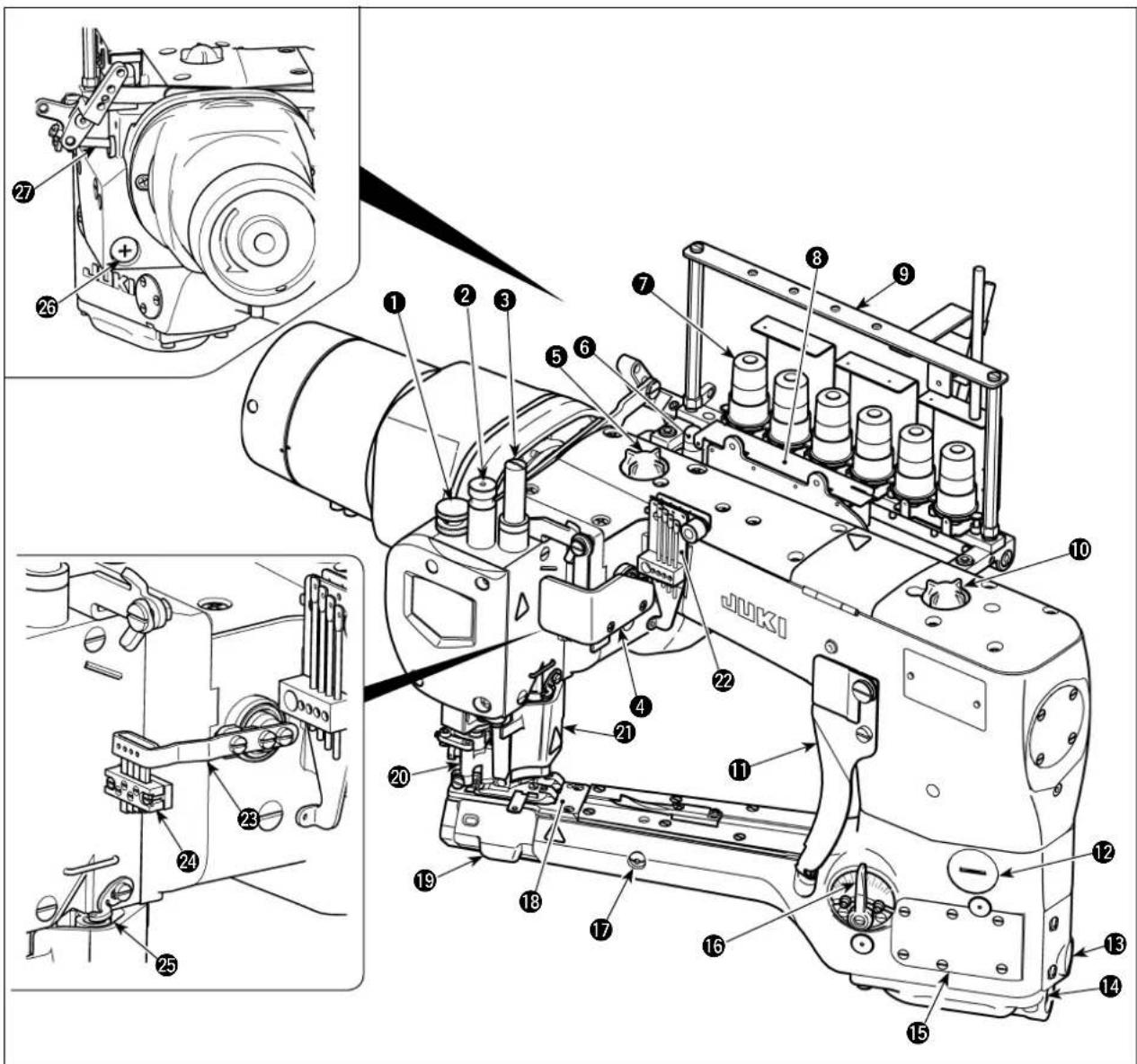
① Micro lifter knob
② Presser spring regulator
③ Needle bar cover
④ Thread take-up lever guard
⑤ Oil circulation inspection windows (rear)
⑥ Oil gauge (rear)
⑦ Thread tension nut
⑧ Needle thread silicon oil lubricating unit
⑨ Thread guide
⑩ Oil circulation inspection windows (front)
⑪ Looper thread guide
⑫ Screw of stitch adjustment window
⑬ Oil gauge (front)
- ⑭ Oil drain screw (front)
⑮ Avoidance adjustment hole
⑯ Differential feed adjusting lever
⑰ Feed inclination adjusting shaft
18 Throat plate
19 Looper cover
20 Presser foot
② Chip guard
22 Needle thread guide
②3 Thread take-up lever
24 Needle thread guard
25 Covering thread guide
26 Oil drain screw (rear)
27 Presser lifter stopper
| 1 Mikrolifterknopf2 Nähfußfederregler3 Nadelstangenabdeckung4 Fadenhebelschutzplatte5 Ölumlauf-Kontrollfenster (hinten)6 Ölstandanzeiger (hinten)7 Fadenspannungsmutter | 8 Nadelfaden-Silikonöl-Schmiereinheit9 Fadenführung10 Ölumlauf-Kontrollfenster (vorn)11 Greiferfadenführung12 Schraube des Sticheinstellfensters13 Ölstandanzeiger (vorn) | 14 Ölablassschraube (vorn)15 Vermeidungseinstellloch16 Differentialtransport-Einstellhebel17 Transportneigungs-Einstellwelle18 Stichplatte19 Greiferabdeckung | 20 Nähfuß21 Schnitzelschutzplatte22 Nadelfadenführung23 Fadenhebel24 Nadelfadenaufnahme25 Deckfadenführung26 Ölablassschraube (hinten)27 Nähfußheberanschlag |
| 1 Bouton du micro-releveur2 Régulateur du ressort du presseur3 Couvercle de la barre à aiguille4 Protecteur du levier rele-veur de fi l5 Regards de contrôle de circulation d'huile (arrière)6 Jauge d'huile (arrière) | 7 Ecrou de tension du fi l8 Unité de lubrification du fil d'aiguille à l'huile siliconée9 Guide-fi l10 Regards de contrôle de circulation d'huile (avant)11 Guide-fil du fil de boucleur12 Vis du regard de réglage de point13 Jauge d'huile (avant) | 14 Vis de vidange d'huile (avant)15 Orifi ce de réglage Avoi-dance adjustment hole16 Levier de réglage du rap-port différentiel17 Arbre de réglage d'inclinai-son d'entraînement18 Plaque à aiguille19 Couvercle du boucleur | 20 Pied presseur21 Pare-copeaux22 Guide du fi l d'aiguille23 Levier-releveur du fi l24 Gaine du fi l d'aiguille25 Guide-fil du fil de recou-vrement26 Vis de vidange d'huile (arrière)27 Arrêtoir du releveur de l' aiguille du presseur |
| 1 Perilla de microelevator2 Regulador del resorte del prensatelas3 Cubierta de barra de agujas4 Protector de palanca tomahilos5 Mirilla de verifi cación de cir-culación de aceite (trasero)6 Manómetro de aceite (trasero) | 7 Tuerca tensora del hilo8 Unidad lubricante con aceite de silicona para hilo de agujas9 Guíahilos10 Mirilla de verifi cación de circulación de aceite (frontal)11 Guía de hilo del enlazador12 Tornillo de mirilla de ajuste de puntada | 13 Manómetro de aceite (frontal)14 Tornillo de drenaje de aceite (frontal)15 Agujero de ajuste de evitamiento16 Palanca de ajuste de transporte diferencial17 Eje para ajuste de incl-nación de transporte18 Placa de agujas | 19 Cubierta del enlazador20 Pie prensatelas21 Protector contra briznas22 Guía de hilo de aguja23 Palanca tomahilos24 Protector de hilo de aguja25 Guía de hilo de recubrimiento26 Tornillo de drenaje de aceite (trasero)27 Retén de alza-prensatelas |
| 1 Manopola del micro-alza-piedino2 Regolatore della molla del pressore3 Coperchio della barra del-l'ago4 Protezione della leva tirafi lo5 Indicatore visivo della circo-lazione dell'olio (posteriore)6 Indicatore di livello del-l'olio (posteriore) | 7 Dado di tensione del fi lo8 Unità di lubrifi cazione con olio di silicone del fi lo del-l'ago9 Guidafi lo10 Indicatore visivo della cir-colazione dell'olio (anterio-re)11 Guidafi lo del crochet12 Vite della fi nestra di rego-lazione del punto | 13 Indicatore di livello del-l'olio (anteriore)14 Vite di scolo dell'olio (an-teriore)15 Foro di regolazione della fuga16 Leva di regolazione del trasporto differenziale17 Albero di regolazione del-l'inclinazione del trasporto18 Placca ago | 19 Coperchio del crochet20 Piedino premistoffa21 Paraschegge22 Guidafi lo dell'ago23 Leva tirafi lo24 Protezione del fi lo dell'ago25 Guidafi lo di copertura26 Vite di scolo dell'olio (post-teriore)27 Fermo dell'alzapiedino |
| 1 微量压脚提升旋钮2 压脚调节螺丝3 针杆护罩4 挑线杆防护器5 机油循环确认窗(后)6 机油尺(后)7 线张力器旋钮 | 8 机线冷却器9 导线器10 机油循环确认窗(前)11 底线导线器12 缝迹长度调节窗螺丝13 机油尺(前)14 排油螺丝(前) | 15 逃逸调节窗16 差动调节拨杆17 传送倾斜调整轴18 针板19 弯针护罩20 压脚21 防护片 | 22 导线器23 挑线杆24 线座25 装饰线导线器26 排油螺丝(后)27 压脚提升止动器 |
II. MAKİNE PARÇALARININ KONFİGÜRASYONU / KONФИГУРАЦИЯ МАШИНЫ
警告:
Be sure to carry out installation of the sewing machine head with two or more persons.
WARNUNG :
JUKI recommends the following combinations of the machine head fi xing base and table.
| Motor used | Machine head fixing base asm. | Table | Auxiliary table |
| Direct-drive motor | DD_CLUTCH_BASE | 40074167 | 40074164 |
| Supplied with the machine head | |||
| Servomotor | MT-01 | 40035801 | 40036113 |
| 40038938 | |||
| Clutch motor | MT-05 | See page 15. | See page 15. |
| 40074840 |
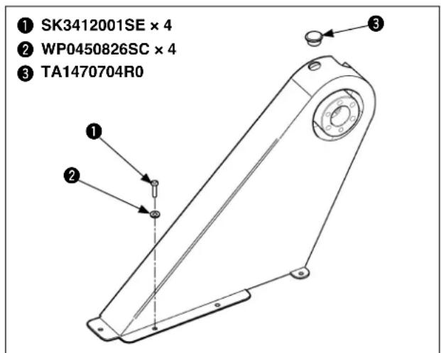
① 40074840
① 40074160
② 40074168×2
③ WP0852086SC×4
④ WS0820002KN×4
⑤ SM90820D3SE×4
40074164 ( 别注文 to be ordered separately / getrennt zu bestellen / à commander séparément / Debe pedirse por separado / Da ordinare separatamente / 特别订货 / ayrica sipariş edilecek / Заказывается отдельно )
When installing the direct-drive motor and the MT-05, install the machine head fixing base ①, auxiliary table ② and rubber cushion ② on the table as shown in the illustration. Be sure to refer to the Instruction Manual for the MT-01 for how to install the MT-01.
A 4-ø 3.4 on the bottom surface, depth 20
[Non-Text]
[Non-Text]
[Non-Text]
A 4-ø 3.4 on the bottom surface, depth 20
クラッチ用補助板図面 Drawing of the auxiliary plate for the machine with a clutch motor /
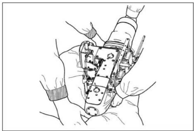
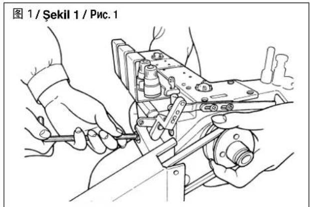
At the beginning, the procedure of pulling out the machine head after opening the package is explained.
1) There is a gap A under the center of the frame. Put there one of your hands and support the machine head.
Next, hold handwheel ① with the other hand.
2) Pull out the machine head while another worker is pressing the packing material.
Next, the procedure of installing the machine head is explained.
2
3
图 1 Fig. 1 / Abb. 1 / Figure 1 / Fig. 1 / Figure 1
Fix the machine head with head fi xing screw ^3 and washer ^2 by two persons or more as shown in Fig. 1. In addition, tightening torque of head fi xing screw ^3 is 12 to 15 N·m.
The work of installing/removing the machine head is accompanied with the danger of the fall of machine head.
Be sure to use the exclusive lift or execute the work with two persons or more and do not take the hands off until the head fi xing screw is securely tightened.
In addition, when tightening the fi xing screw, laterally adjust the head position so that V-belt is set straight.
If the V-belt is set bent, the progress of abrasion of V-belt is increased.
natural_image
Illustration of hands assembling a mechanical component (no text or symbols visible)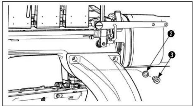
首先,说明一下开箱后机头的取出方法。
How to install the belt cover for the direct-drive motor /
1) Attach belt cover C ① to the arm support (on the motor side) by means of two setscrews ②.

moving or tilting the machine head,
be sure to remove belt cover C ①.
3) Temporarily fi x idler (asm.)⑤ at the location shown in the illustration by means of the two setscrews ⑥.
4) Adjust the angle of idler (asm.) ⑤ so that the belt sags 4 mm when the approximate center of the span of belt ③ is pressed with a 3 N (300 g) load. After completion of the adjustment, fix the idler (asm.) by securely tightening two setscrews ⑥.
Rotate the belt by two or three revolutions every time you have changed the angle of idler (asm.) ⑤ to break in the belt. Then, measure the amount of the belt sagging.

- Be sure to fi rmly tighten two setscrews⑥. If they loosen, the belt can slip off from the sprocket (asm.) erence value of the tightening torque: 30 ± 5 kgfcm ( 3.0 ± 5 N m)
- If the belt comes in contact with the cover while the sewing machine is in operation, stretch the belt.
5) Insert belt cover (asm.) ⑦ into the clearance in the direct-drive motor base and fi x it at the location shown in the illustration by means of three setscrews ⑧.
natural_image
Technical line drawing of a mechanical assembly with labeled component (9), no readable text or symbols present6) Bundle the motor cable and others using a cable clip ⑨, and fix it with a fixing screw ③ at the top side of the belt cover (asm.) ⑦.
(2) Per il SC-910
- Change the setting 95 to MF3d.
(2) Für SC-910
- Change the setting 95 to MF3d.
(3) Für SC-921
(1) For the machine using a servomotor (MT-01, SC-510/M51), the belts should be combined as shown in the table below.
| Mount base | Control box/Motor Motor pulley | *1 | Belt on the motor side *1 | Belt on the machine head side *2 |
| MT-01 SC-51 | 10/M51 | Outside diameter φ115 | M-type 35 inches M-type | 29 inches |
| MTSP0110000 MTJVM | 003500 MTJVM002900 |
^*1 Included in the MT accessories for the SC-510 (part number: 40039132). ^2 Included in the accessories for the MT-01.
(2) See the following table for the machine using a clutch motor of 3-phase 2-pole 400-watt (1/2 HP).
| Outside diameter of pulley (mm) | Sewing speed (sti/min) Belt size | |
| 50Hz 60Hz Suspension type | ||
| 45 2600 M-57 | ||
| 50 2900 M-57 | ||
| 55 2700 3200 M-57 | ||
| 60 2900 3500 M-57 | ||
| 65 3150 3800 M-58 | ||
| 70 3400 4100 M-58 | ||
| 75 3650 M-58 | ||
| 80 3900 M-59 | ||
| 85 4150 M-59 | ||
* The commercially-available motor pulley near to the counted value is designated since the outside diameter of the commercially-available motor pulley counts by 5 mm.

Use a motor pulley which is adaptable to this sewing machine. The sewing speed exceeds the max. sewing speed of this sewing machine and machine trouble will be caused unless a motor pulley which is adaptable to this sewing machine is used.

When you use a new sewing machine, use the machine at a speed of 3,200sti/min or less for the first 200 hours (approximately one month). A good result can be obtained in terms of the durability.
1)カラー①及びスペーサー②を止めねじ 3 本で取付けます。
1) Attach collar ① and spacer ② with three setscrews.
1) Muffe ① und Distanzring ② mit drei Befestigungsschrauben anbringen.
1) Attacher le collier ① et l'entretoise ② avec trois vis de serrage.
1) Instale el collarín ① y el espaciador ② con los tres tornillos de fi jación.
1) Attaccare il collare ① ed il distanziale ② con tre viti di fi ssaggio.
1)用3个固定螺丝安装套环①和垫片②。
1) Rakoru ① ve pulu ② üç tespit vidasıyla takın.
1) Скрепите втулки ① и распорки ② тремя крепежными винта-
ми.
2)ベルトカバー③の中にVベルト④を入れます。
2) Place V-belt ④ in belt cover ③.
2) Den Keilriemen ④ in die Riemenabdeckung ③ einführen.
2) Introduire la courroie trapézoïdale ④ dans le couvercle de courroie ③.
2) Coloque la correa-V ④ en la cubierta ③ de la correa.
2) Mettere la cinghia a V ④ nel copricinghia ③.
2)把 V 形皮带④放到皮带护罩③的里面。
2) V kayışı ④ kayış kapağına ③ yerleştirin.
2) Расположите клиновой ремень ④ места в кожухе ③.
natural_image
Technical line drawing of a mechanical component with concentric rings and mounting holes (no text or symbols)3) Haga pasar la cubierta ③ de la correa a través de la polea de la máquina de coser. Coloque la correa-V ④ en la polea.
3) Fare passare il copricinghia ③ attraverso la puleggia della macchina per cucire. Mettere la cinghia a V ④ sulla puleggia.
3) Kayış kapağını ③ dikiş makinesinin kasnağına geçirin. V kayışı ④ kasnağa takın.
6) Attach pulley ⑥ and pulley holder ⑦ to spacer ② using three setscrews ⑧.
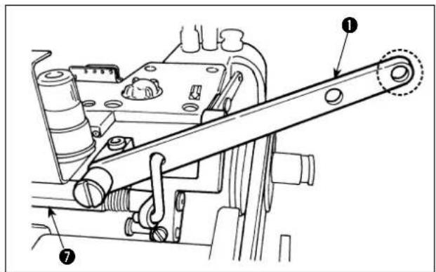
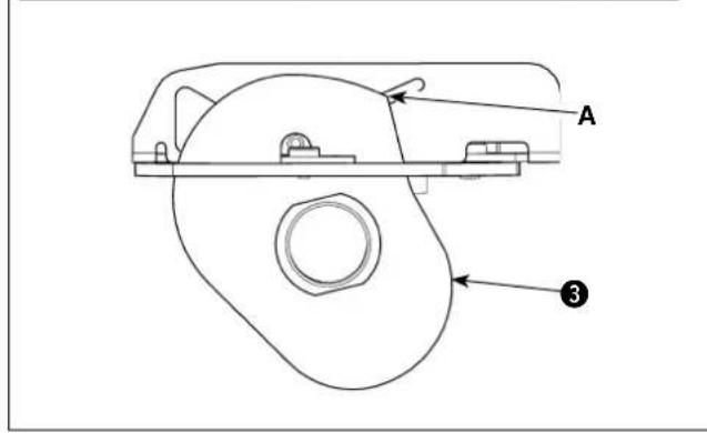
At the beginning, insert boss section A of presser lifting lever 1 into bracket 2.
In this state, fi x it on thread tension base⑦ with setscrew ③.
Next, pass connecting link ⑤ as shown in the figure and insert O-ring ⑥ into the both ends of it.
Finally, fi x it with setscrew④.

Apply the grease (Part No.: 40013640) supplied with the unit to the sliding parts encircled with ○(four locations) at least once every year.
natural_image
Technical line drawing of a mechanical assembly with no visible text or symbolsDirection of rotation of the sewing machine is the same as that of the hand of watch as viewed from the handwheel side. It is counterclockwise as viewed from the working position of the operator.
Never rotate it in the reverse direction. Lubricating pump fails to work and seizure will be caused.
Attach studs ① to studs ④, supplied with the unit. Fix thread guide ② on studs ① with screws ③.
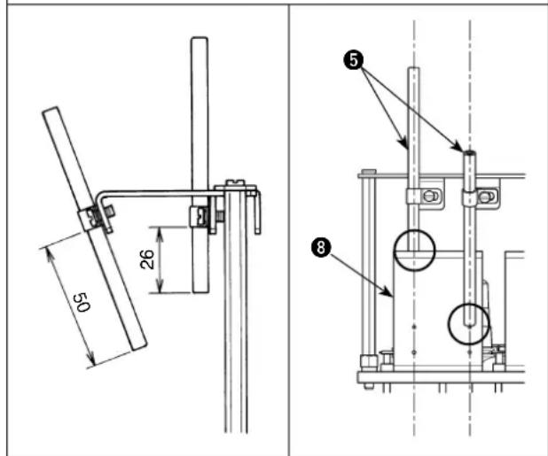
Then, fi x looper thread and covering thread guide pipes ^5 on thread guide ^2 with pipe fi xtures ^6 and fl at screws ^7 to provide the dimensions given in the illustration below (two points).
Adjust the rightward/leftward tilt of thread guide pipe 5 so that the center of the hole in the pipe meets the center of the thread path hole in thread tension thread guide plate 8.
Fix thread stand asm. ① on the machine table with nuts ②, washers ③ and spring seat ④ as illustrated in the sketch.
Putting chain-off thread cutting knife guard ② on chain-off thread cutting knife ①, install them together on the sewing machine with two setscrews ③.
When installing the chain-off thread cutting knife on the sewing machine, be extremely careful not to allow your fingers to be cut by the knife.
1) Remove oil circulation inspection windows ①.
2) Pour JUKI New Defrix oil No.2.
3) For the oil to be added through oil hole (front) A, pour it until the indicator bar reaches short of the upper red engraved marker line while visually observing oil gauge ② from the side.
4) Remove oil plug ③.
5) For the oil to be added through oil hole B, pour it until the oil surface comes short of the upper engraved marker line while visually observing oil gauge 4 from the side.

is added until the oil surface is above the upper engraved marker line, the oil quantity is excessive resulting in oil leakage. Be sure to stop adding oil before the oil surface reaches the upper engraved marker line.
When the machine is used for high-speed sewing or with synthetic thread and synthetic cloth, open cover ② of silicon container ① and add silicon oil (dimethyl silicone) into the container to prevent thread breakage or stitch skipping.

icon oil adhered to the components other than the silicon container, be sure to wipe it out. If the components to which silicon oil adhered are kept being used without wiping out the oil, sewing machine trouble will be caused.
Open silicon container cover 7, thread take-up lever guard 8, chip guard 9, top cover B 10, looper thread guide cover 11 and looper cover 12, and properly thread the machine head. 1 to 4 are needle thread, 5 is top covering thread and 6 is looper thread. After completion of threading, be sure to close the covers back in place.
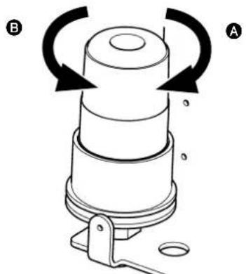
Turn presser spring regulator ① clockwise to increase the pressure, or counterclockwise to decrease it.
5. 差動比の調節 Adjusting the differential feed ratio /
The differential feed ratio is increased by moving differential feed adjusting lever ① to the right. In this case, the finished material is gathered. The ratio is decreased by moving the lever to the left. In this case, the finished material is stretched.
Setscrew ② is used for fi xing lever ① and keeping the differential feed amount constant.
1) Remove plug screw ① and O-ring ②.
2) Loosen setscrew ③ and adjust the stitch length by moving the screw upward or downward. At this time, be sure to only loosen setscrew ③ instead of removing it.
3) Tighten setscrew ③ and attach plug screw ① and O-ring ② back in place.
4) Check to be sure that the rear needle guard does not come in excessive contact with the needle.

Be sure to adjust the stitch length after having completed the adjustment of the differential feed.
natural_image
Diagram of a mechanical device with rotating arrows indicating rotation, labeled A and B (no text or symbols on the diagram itself)A = 締まる / Increase / Erhöhen / Augmentation / Aumento / Aumento / 拧紧 / Artar / Увеличение
B = ゆるむ / Decrease / Verringern / Diminution / Disminución / Diminuzione / 拧松 / Azalir / Uменьшение
Adjust the thread tension with the following thread tension nuts.
① Needle thread tension nut
② Top covering thread tension nut
③ Looper thread tension nut
Turn clockwise to increase the thread tension.
Turn counterclockwise to decrease the thread tension.
Bring the needle bar to its lowest position and loosen set-screw ②. Adjust the knife pressure by moving knife mounting base guide collar ① upward or downward. Move the collar upward to increase the knife pressure, or downward to decrease it. Standard height A of knife mounting base guide collar ① is 1.0 mm.
When tightening setscrew
②, be sure to check

that knife ③ is located at a position where it does not interfere with the presser foot.
1) When the needle bar is in its upper dead point, loosen setscrew ①. Move needle clamp ② upward or downward to adjust distance A from throat plate ③ to the top end of right needle ④ to 13.5 mm when the needle gauge is 5.2 mm, or to 12.7 mm when it is 6.0 mm.
2) After the adjustment, adjust the relation between the needle hole in the throat plate and the needle so that clearances B is uniform.
3) Tighten setscrew ①.
To protect against possible personal injury due to abrupt start of the machine, be sure to start the following work after turning the power off and ascertaining that the motor is at rest.
■ 押えの取り外し方
■ How to remove the presser foot
1) Remove the needle.
2) Remove setscrews ② (4 pcs.) to remove face plate ①.
3) Loosen presser spring regulator ③. Loosen setscrew ④ in the presser bar position bracket.
4) Loosen screw 5 in the knife mounting base guide collar to let the assembly including the upper knife, knife mounting base and shaft move freely.
5) Loosen setscrews⑦ (2 pcs.) to remove knife mounting base guide ⑥ from knife driving base ⑧ together with the upper knife and other related parts.
6) Loosen setscrew ⑨ in the presser foot to remove presser spring regulator ③. Then, lift the presser bar to such an extent that it is disengaged from the presser foot.
7) Remove carrier hook segment ⑪ of the presser foot from the lever section of carrier hook sleeve ⑩.
8) Remove the presser foot diagonally backward while turning it in the direction of the arrow.
■ How to install the presser foot
① Attach the presser foot between the presser guides (right) and (left) from diagonally backward while turning it counterclockwise.
② Fit carrier hook segment ⑪ into the lever section of carrier hook sleeve ⑩.
③ Put the presser bar in carrier hook segment ⑪ and temporarily fix with setscrew ⑨.
④ Check to be sure that the presser foot moves up and down smoothly with no lateral backlash. If it does not, loosen setscrew 13 in presser foot guide (left) 12 to adjust the presser foot properly.
⑤ Attach knife mounting base guide ⑥ on knife driving base ⑧ together with the upper knife and other related parts with setscrews ⑦ (2 pcs.).
⑥ Bring the needle bar to its lowest position. Adjust the position of knife mounting base guide collar ⑤ and that of the upper knife. (Refer to p. 46 for the adjusting procedure.)
⑦ Attach presser spring regulator ③. Loosen setscrew ⑨ in the presser foot once to check to be sure that the stepped part of the presser bar comes in contact with the main body of the presser foot. Then, tighten setscrew ⑨ in the presser foot.
⑧ When the micro-lifter function (p.46) is used, deactivate it once. Tighten the setscrew in presser bar position bracket ④ with clearance A of 1 mm provided between presser bar position bracket ④ and damper ⑭.
⑨ Attach face plate ① with setscrews ② (4 pcs.).
⑩ Attach the needle.
⑪ When the micro-lifter function is used, adjust it after completion of the aforementioned steps of procedure.

WARNUNG :

¡AVISO!
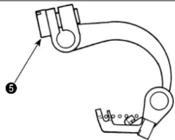
Adjusting the covering thread carrier and covering thread hook /
■ 飾り糸キャリア
■ Covering thread carrier
Loosen setscrew ③. Adjust so that the covering thread loop made by the thread eyelet section goes behind the left needle and left medium needle when covering thread carrier ① approaches closest to the needle.
■ Covering thread hook
Loosen setscrew ⑤. Adjust so that a clearance of 0.5 mm is provided between covering thread hook ② and retainer needle ④ when covering thread hook reaches its rightmost position.
Turn the sewing machine by one revolution to check to be sure that covering thread hook ② does not come in contact with covering thread carrier ①.

Adjusting covering thread carrier ① and covering thread hook ②, take care to avoid a longitudinal backlash.
natural_image
Mechanical linkage diagram showing a curved arm with joints and a numbered label (5), no text or symbols present.To protect against possible personal injury due to abrupt start of the machine, be sure to start the following work after turning the power off and ascertaining that the motor is at rest.

WARNUNG :
■ 上メスの交換・調整
■ Replacing/adjusting the upper knife
1) Loosen upper knife fi xing screw 3. Lift knife mounting base ① upward to draw out upper knife ②. Then, replace it with a new one.
2) Adjust the position of upper knife ② so that its depth of mesh with lower knife ④ is 0.3 to 0.7 mm when the upper knife reaches its leftmost position. Then, tighten knife fi xing screw ③.
■ 下メスの交換・調整
■ Replacing/adjusting the lower knife
1) Loosen lower knife fi xing screw ^5 . Lift knife mounting base ^1 upward to draw out lower knife ^4 . Then, replace it with a new one.
2) Adjust the position of lower knife ④ so that distance B of 0.8 to 1.6 mm is provided between its blade point A and the main body of the presser foot. Then, tighten lower knife fi xing screw ⑤.
natural_image
Technical line drawing of a mechanical assembly with springs and mounting base (no text or symbols)■ Adjusting the angle of mesh of the knife
Loosen upper knife fixing screw ③. Adjust the knife angle by turning knife angle adjusting screw ⑥ with the hexagonal wrench supplied with the unit. Then, tighten upper knife fixing screw ③.
5. 送り歯高さの調整 Adjusting the height of the feed dog /
1) Bring the feed dog to its highest position and loosen setscrew ④ in main feed dog ③
2) Adjust so that crestA of main feed dog ③ is positioned 1.2 to 1.5 mm higher than the top surface of the throat plate. Then, tighten setscrew ④.
3) Loosen setscrew ② in differential feed dog ①. Adjust the position of differential feed dog ① so that it is flush with main feed dog ③. Then, tighten setscrew ②.
1) Den Transporteur in seine Höchstposition bringen, und die Befestigungsschraube ④ im Haupttransporteur ③ lösen.
Rückstellbetrag
When looper ① reaches its leftmost position, the standard distance between the top end of looper ① and the center of the left needle is 4.0 to 4.4 mm for the needle gauge of 5.2 mm, or is 4.6 to 5.0 mm for the needle gauge of 6.0 mm. Loosen setscrew ② in the looper base and carry out adjustment.
Volume de retour
Adjust so that a clearance of 0 to 0.05 mm is provided between the top end of looper ① and left needle ③ when the looper moves from the left to the right to reach the position at which the top end of looper ① aligns with the center of the left needle.
1) Loosen setscrew ②. Turn adjusting screw ⑤ clockwise to move looper base ④ toward the operator side, or counterclockwise to move it away from the operator side.
2) Tighten setscrew ^② . Then, check the return amount.
7. 針受け(前)の調整 Adjusting the needle guard (front) /
Loosen setscrews ② (2 pcs.) in needle guard (front) ①. Adjust so that a clearance of 0 mm is provided between looper ③ and the left needle when looper ③ moves from the left to the right to reach the position at which the top end of looper ③ aligns with the center of the left needle. After the adjustment, check to be sure that, when looper ③ is moved from the left to the right, the back face of the needle comes in contact with the top end of the looper and the needle does not deviate to the right.
The standard clearance A between needle guard (rear) ① and the needle is 0.05 to 0.1 mm when needle guard (rear) ① approaches closest to left needle ③. Loosen setscrew ② and adjust the needle guard (rear).
After the adjustment, check to be sure that, when looper is moved from the left to the right, the needle does not deviate to the right.
natural_image
Mechanical assembly diagram showing linkage mechanism with no visible text or symbols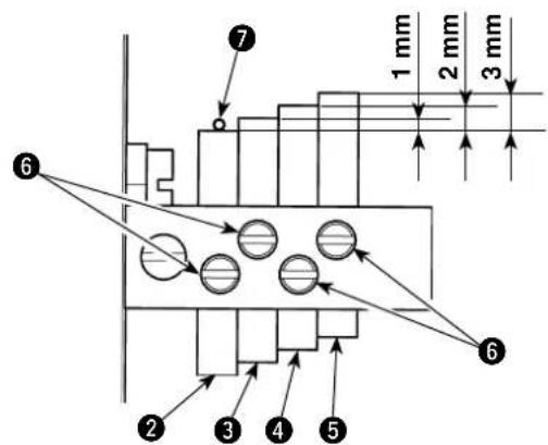
1) Bring thread take-up lever ① to its lowest position.
2) Loosen screw 6. Adjust the height of the top end of needle thread guard 2 to the height of needle thread 7 of the right needle. Fix the needle thread guard with screw 6.
3) Raise the top end of needle thread guard ③ above the top end of needle thread guard ② by 1 mm and fi x with screw ⑥.
4) Raise the top end of needle thread guard ④ above the top end of needle thread guard ② by 2 mm and fi x with screw ⑥.
5) Raise the top end of needle thread guard ⑤ above the top end of needle thread guard ② by 3 mm and fi x with screw ⑥.

to be sure that the top ends of the respective needle thread guards are in a horizontal position.
Loosen screw ⑥ and adjust the size of the needle thread loop by moving the needle thread guard upward or downward. Move the needle thread guard upward to increase the size of the needle thread loop, or downward to decrease it.
natural_image
Mechanical assembly diagram showing linkage mechanism with no visible text or symbols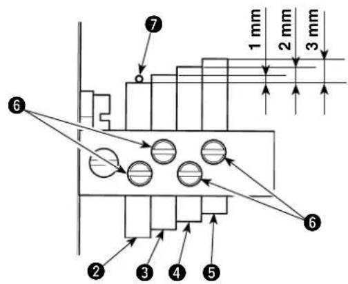
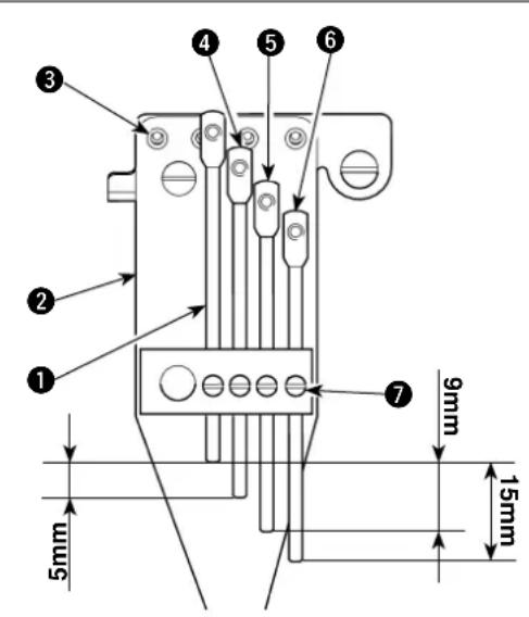
1) Loosen screw 7. Align the height of the hole in needle thread path ① with hole ③ in needle thread path base ②. Fix the needle thread path with screw ⑦.
2) Loosen screw ⑦. Adjust the height of needle thread path ④ so that it is lower than needle thread path ① by 5 mm.
3) Loosen screw ⑦. Adjust the height of needle thread path ⑤ so that it is lower than needle thread path ① by 9 mm.
4) Loosen screw ⑦. Adjust the height of needle thread path ⑥ so that it is lower than needle thread path ① by 15 mm. Move the needle thread path downward to tense the needle thread, or upward to loosen it. Finely adjust the thread tension according to the material or thread to be used.
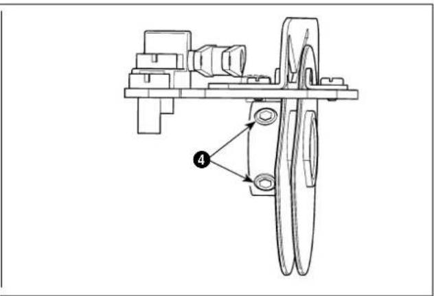
1) Open top cover B① and looper thread guide cover ②.
2) The standard timing that the looper thread passes crest A of looper thread cam ③ is when the needle bar comes down from its highest position by 2.8 mm. Loosen setscrews ④ (2 pcs.) to adjust the looper thread cam.
If the timing for looper thread cam ③ is advanced, the looper thread take-up amount will be increased. If the timing is retarded, it will be decreased.
3) After completion of the adjustment, close top cover B ① and looper thread guide cover ②.

When fi xing looper the already prevent it from coming in contact with cam thread guide mounting base (asm.) ⑤. If the former comes in contact with the latter, stitching failures or noise can be caused.
Loosen setscrew ②. Then, the lateral position of looper thread cam thread guide ① can be adjusted.
The standard adjustment is obtained by positioning looper thread cam thread guide ① at its rightmost position.
Moving looper thread cam thread guide ① to the left increases the looper thread take-up amount.

When
thread cam.
fi xing looper thread cam thread, gradually prevent it from coming in contact with looper
If the former comes in contact with the latter, stitching failures or noise can be caused.
Loosen setscrew ②. Then, the thread eyelet height in covering thread guide ① can be adjusted.
The standard adjustment of the distance between the top surface of looper thread guide plate ③ and the top surface of the top end of covering thread guide ① is 5.2 mm.
Move covering thread guide ① downward to increase the covering thread take-up amount, or upward to decrease it.

When
fi xing covering that carefully prevent it from coming in contact with covering thread cam ④.
If the former comes in contact with the latter, stitching failures or noise can be caused.
natural_image
Mechanical assembly diagram showing a linkage mechanism with no visible text or symbols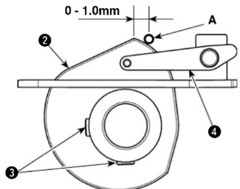
A: 飾り糸 / Covering thread / Deckfaden / Fil de recouvrement / Hilo de recubrimiento / Filo di copertura / 装饰线 / Kaplama ipligi / Декоративная нити
Loosen setscrews ③ (2 pcs.) to adjust the timing for covering thread cam ②.
The standard timing for the covering thread cam is obtained by adjusting the cam so that the covering thread A rests within 0 to 1 mm from the crest of the cam when covering thread hook ① catches the covering thread.

When fi xing covering the successfully prevent it from coming in contact with covering thread guide ④.
If the former comes in contact with the latter, stitching failures or noise can be caused.
Loosen setscrew ② to adjust the lateral position of lap former ①.
Adjust the lateral position of the lap former according to how the right and left materials overlap or the state of the feed.
To protect against possible personal injury due to abrupt start of the machine, be sure to start the following work after turning the power off and ascertaining that the motor is at rest.

WARNUNG :
Remove presser foot ① and throat plate ②. Clean up the grooves in the throat plate, grooves in the feed dog teeth and the peripheries of looper ③ and rocker arm ④.
natural_image
Technical line drawings of mechanical components, showing top and side views with no visible text or symbolsIn case of the new sewing machine, replace the lubricating oil (JUKI New Defrix oil No.2) with new one after using it for approximately one month. Then replace the lubricating oil every six months.
Two oil drain openings are provided as shown in the illustration.
When tilting the machine head in order to

drain oil, remove the belt cover C referring to "Ⅲ-1-3. How to install the belt cover for the direct-drive motor" p.19.
natural_image
Technical line drawings of mechanical components, showing top and side views with no visible text or symbolsAs a guide, apply grease supplied with the unit on the sliding surface between carrier hook sleeve ① and presser foot segment ② periodically once a year.
In addition, apply grease on the above-stated sliding surface also when the presser foot is replaced.
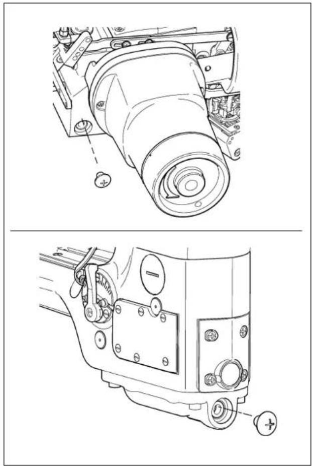
How to install the control box(Only for MF-3620*B) /
① 化粧ボルト ( 頭部付属)
② 電装 BOX 付属品
③ 電装取り付け板
④ ばね座金
⑤ ナット
⑥ 防振ゴム
⑦ 座金
1 Decoration bolt (supplied with the machine haed)
② Accessories for control box
③ Control-box mounting plate
④ Spring washer
⑤ Nut
6 Rubber cushion
⑦ Washer
Suspend the control box from underside of the table, as shown in the above illustration, at each of the three supporting points with washer ⑦, spring washer ④ and nut ⑤ while placing bracket ③ and rubber piece ⑥ supplied with the unit between the box and the table.
- If you use the decoration bolt supplied with the SC-921, the control box cannot be installed since the

bolt interferes with the control box.
- If the control-box mounting plates are fixed on the table in a wrong installing direction or with the hole located at a wrong position, the control box cannot be installed.
SEWING MACHINERY BUSINESS UNIT
2-11-1, TSURUMAKI, TAMA-SHI,
Copyright © 2010-2013 JUKI CORPORATION
• All rights reserved throughout the world.
Please do not hesitate to contact our distributors or agents in your area for further information when necessary. * The description covered in this instruction manual is subject to change for improvement of the commodity without notice.