Royal - Electric bike EMG - Free user manual and instructions
Find the device manual for free Royal EMG in PDF.
| Product type | Electric bike |
| Brand | EMG |
| Model | Royal |
| Maximum permissible weight | 150 kg (bike + user + equipment) |
| Available battery types | 36 V, capacities from 8.8 Ah to 14.5 Ah, rack, frame or integrated mounting |
| Battery charge cycles | Approximately 1000 cycles at 100% discharge |
| Battery weight (depending on model) | From 2.55 kg to 4.5 kg |
| Motor type | Front, center or rear depending on version |
| Display and controls | LED or LCD units depending on version (DP E06, DP E12, KD59E, DP C10, DP C07, KD21C, Shimano STEPS) |
| Assistance levels | From 0 to 5 depending on control unit |
| Walk assistance function | Yes, constant speed 4-6 km/h by holding the button |
| Wheel sizes | 26", 27.5", 28" or 29" depending on version |
| Brakes | V-brake or hydraulic disc depending on version |
| Transmission | Front/rear derailleur, cassette, manual or automatic gear shifting depending on version |
| Lighting | Powered by battery, handlebar switch |
| Folding | Available on some models (folding bike) |
| Battery warranty | 6 months from purchase |
| Consumer warranty | 2 years (per legislation) |
| Recommended maintenance | Inspection every 500 km or 6 months, then 1000 km or 12 months |
| Cleaning | With clean water and a soft sponge, avoid high pressure |
Frequently Asked Questions - Royal EMG
User questions about Royal EMG
0 question about this device. Answer the ones you know or ask your own.
Ask a new question about this device
Download the instructions for your Electric bike in PDF format for free! Find your manual Royal - EMG and take your electronic device back in hand. On this page are published all the documents necessary for the use of your device. Royal by EMG.
USER MANUAL Royal EMG
electric moving green

ISTRUZIONI PER L'USO

OPERATING INSTRUCTIONS

BEDIENUNGSANLEITUNG

NOTICE D'UTILISATION
natural_image
Black rectangular electronic device with a transparent lens, resting on a plain white surface (no text or symbols visible)
natural_image
Exterior view of a modern office building (no signage)
natural_image
Black rectangular electronic device with a flat top and side panel, shown against a plain background (no text or symbols visible)
natural_image
Black rectangular electronic device with a gold connector, isolated on white background (no text or symbols visible)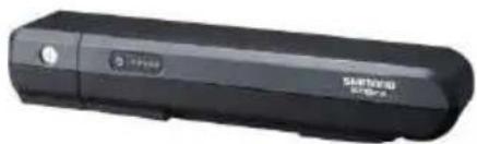
natural_image
Black USB flash drive with brand logo (no visible text or symbols on body)Modello: DEVRON ELECTRIC
Tensione: 36V
natural_image
Black office phone handset with no visible text or symbols on the device body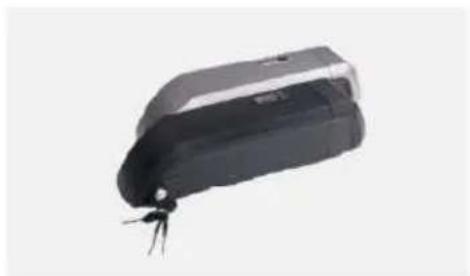
natural_image
Black rectangular electronic device with a small metallic connector at the bottom (no visible text or symbols)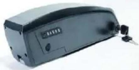
natural_image
Exterior view of a black electronic device with a small attached component (no visible text or symbols)natural_image
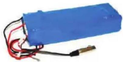
Blue battery with red and black wires, no visible text or symbolsModello: Shimano BT E-6000 DT
Tensione: 36V
natural_image
Close-up of a hand using a clamping tool to adjust or install a mechanical component (no visible text or symbols)Pic.1
natural_image
Close-up of a bicycle front bumper with visible tire and metal brackets (no text or symbols)Pic.2
natural_image
Close-up of a bicycle's front wheel and suspension components (no visible text or symbols)Pic.3
natural_image
Two black mechanical components with metallic fittings and triangular connectors (no visible text or symbols)Pic.4
natural_image
Close-up of a metallic tool with a textured grip and triangular base, resting on a flat surface (no text or symbols visible)Pic.5

natural_image
Close-up of a robotic hand holding a device with a numbered callout (no visible text or symbols)natural_image
Close-up of a person wearing a medical or surgical device with visible tubing and a small connector (no text or symbols)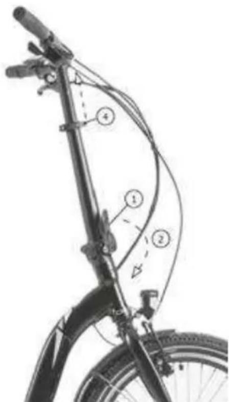
natural_image
Line drawing of a person riding a bicycle (no text or symbols)Pic. 1
natural_image
Simple line drawing of a mechanical component with a spring and arrow indicating motion (no text or symbols)Pic. 2
natural_image
Diagram of a liver with directional arrows indicating movement or force (no text or labels)Pic. 3
natural_image
Anatomical illustration of a mechanical joint or implant structure (no text or labels)Pic. 4
PEDALI
IL SISTEMA DI LUCI
natural_image
Close-up of a bicycle wheel rim with visible tire and spokes (no text or symbols)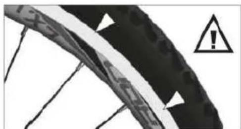
natural_image
Close-up of a damaged cable with warning symbol (no readable text or labels)Pic.2
Pneumatici
natural_image
Two black-and-white photos showing a bicycle pedal mechanism on tiled floor, with arrows indicating the mechanism (no text or symbols present)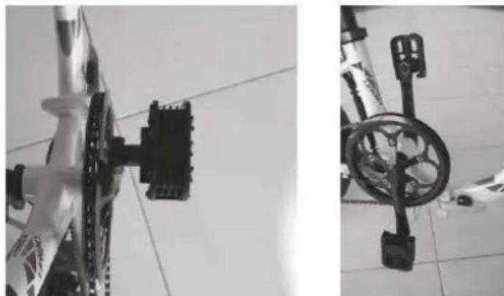
natural_image
Two black-and-white photos showing bicycle wheel assembly and weight scale on tiled floor (no text or symbols visible)natural_image
Three-panel black-and-white photo showing a bicycle leotard with a key inserted into the wheel, no visible text or symbols.natural_image
Close-up of a robotic arm with a tool inserted, showing no visible text or symbols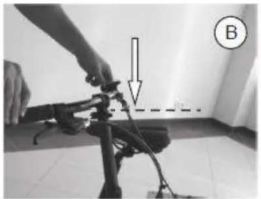
natural_image
Person adjusting a camera frame with a downward arrow and dashed line, labeled B (no text or symbols on the device itself)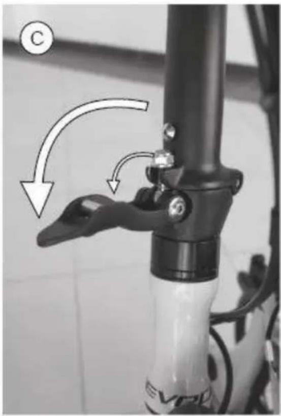
natural_image
Close-up of a bicycle head lever mechanism with arrows indicating motion direction (no text or symbols)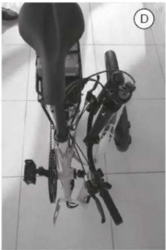
natural_image
Top-down view of a mechanical device with attached components on tiled floor (no visible text or symbols)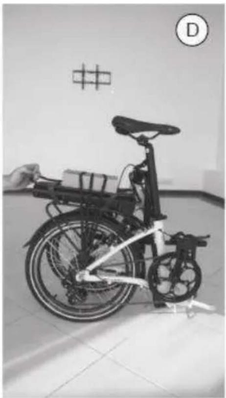
natural_image
Black-and-white photo of a bicycle with a hand adjusting its side panel, displayed indoors near a wall with a grid pattern (no visible text or symbols)Unità DP E06 LED
2. Funzioni
2.1 Pulsante Start / Stop
2. Funzioni
2.1 Pulsante Start / Stop
2. Display

Unità Shimano STEPS SCE 6010 / SCE 6000
Caratteristiche
UNITÀ DI CONTROLLO
Esci
natural_image
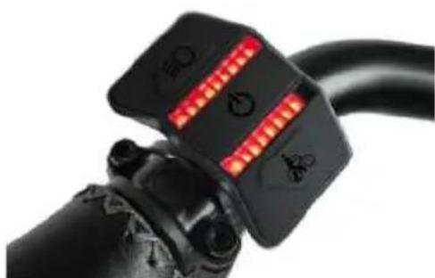
Close-up of a black bicycle brake lever with illuminated red indicator lights and warning symbols (no text or labels visible)BATTERIA
natural_image
Close-up of a server rack with labeled components (no readable text or symbols)
natural_image
Close-up of a black plastic component with a small inset detail, no visible text or symbols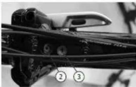
natural_image
Close-up of a mechanical component with wires and a tool, labeled 2 and 3 (no readable text or symbols)natural_image
Close-up of a black bicycle rear bumper with visible branding and control panels (no readable text or symbols)natural_image
Simple line drawing of a trash bin with crossed lines indicating no waste or discharge (no text or symbols)natural_image
Simple line drawing of a trash bin with no text or symbolsnatural_image
Recycling symbol composed of three chasing arrows forming a triangle (no text or labels)natural_image
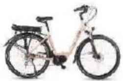
Side view of a modern electric bicycle with front wheel and rear seat (no visible text or symbols)IL PRODOTTO È CONFORME A TUTTE LE DISPOSIZIONI PERTINENTI DELLE SEGUENTI DIRETTIVE / THE PRODUCT COMPLIES WITH ALL RELEVANT PROVISIONS OF THE FOLLOWING DIRECTIVES:
DIRETTIVA 2006/42/EC / DIRECTIVE 2006/42/EC DIRETTIVA 2015/863/EU / DIRECTIVE 2015/863/EU DIRETTIVA 2014/30/EU / DIRECTIVE 2014/30/EU DIRETTIVA 2014/35/EU / DIRECTIVE 2014/3/EU
RIFERIMENTO ALLE PERTINENTI NORME ARMONIZZATE UTILIZZATE / THE FOLLOWING HARMONIZED STANDARDS AND TECHNICAL SPECIFICATIONS HAVE BEEN APPLIED:
| TITOLO / TITLE: | DATA DI PUBBLICAZIONE / DATE OF STANDARDS |
| EN62471 | 2008 |
| EN15194 | 2017 |
| EN ISO 4210-1 LA 9 | 2014/2015 |
FIRMATO A NOME E PER CONTO DI / SIGNED FOR AND ON BEHALF OF:
RIMINI, 18.11.2021
(LUOGO E DATA DEL RILASCIO / PLACE AND DATE OF ISSUE)
TREVI S.P.A. LE PRÉSIDENT TREVI S.P.A. DER PRÉSIDENT AGUTI FGIDIO (NOM. FONCTION, SIGNATURE NAME, FUNKTION, UNTERCHRIFT)
DICHIARAZIONE DI CONFORMITÀ UE EU DECLARATION OF CONFORMITY (DOC)
| NOME DEL FABBRICANTE / COMPANY NAME: | TREVI S.P.A. | |
| INDIRIZZO POSTALE / POSTAL ADDRESS: | STRADA CONSOLARE RIMINI – SAN MARINO, 62 | |
| CAP E CITÀ / POSTCODE AND CITY: | 47924 | RIMINI (RN) - ITALY |
| TELEFONO / TELEPHONE: | +39 0541.756420 | |
| INDIRIZZO POSTA ELETTRONICA / E-MAIL ADDRESS: | INFO@TREVI.IT | |
| PERSONA AUTORIZZATA ALLA COMPILAZIONE DEL FASCICOLO TECNICO | AGUTI EGIDIO – STRADA CONSOLARE RIMINI – SAN MARINO, 62 47924 RIMINI (RN) ITALY | |
LA PRESENTE DICHIARAZIONE DI CONFORMITÀ È RILASCIATA SOTTO LA RESPONSABILITÀ ESCLUSIVA DEL FABBRICANTE / DECLARE THAT THE DOC IS ISSUED UNDER OUR SOLE RESPONSIBILITY:
| APPARECCHIO MODELLO / APPARATUS MODEL: | UB 28RA - 28414 |
| TIPO PRODOTTO / PRODUCT TYPE: | BICICLETTA A PEDALATA ASSISTITA – EBIKE |
| LOTTO / LOT | 04/22 |
OGGETTO DELLA DICHIARAZIONE / OBJECT OF THE DECLARATION:
natural_image
Exterior view of a modern bicycle with black frame and white body (no visible text or symbols)IL PRODOTTO È CONFORME A TUTTE LE DISPOSIZIONI PERTINENTI DELLE SEGUENTI DIRETTIVE / THE PRODUCT COMPLIES WITH ALL RELEVANT PROVISIONS OF THE FOLLOWING DIRECTIVES:
DIRETTIVA 2006/42/EC / DIRECTIVE 2006/42/EC DIRETTIVA 2015/863/EU / DIRECTIVE 2015/863/EU DIRETTIVA 2014/30/EU / DIRECTIVE 2014/30/EU DIRETTIVA 2014/35/EU / DIRECTIVE 2014/3/EU
RIFERIMENTO ALLE PERTINENTI NORME ARMONIZZATE UTILIZZATE / THE FOLLOWING HARMONIZED STANDARDS AND TECHNICAL SPECIFICATIONS HAVE BEEN APPLIED:
| TITOLO / TITLE: | DATA DI PUBBLICAZIONE / DATE OF STANDARDS |
| EN62471 | 2008 |
| EN15194 | 2017 |
| EN ISO 4210-1 LA 9 | 2014/2015 |
FIRMATO A NOME E PER CONTO DI / SIGNED FOR AND ON BEHALF OF:
RIMINI, 18.11.2021
(LUOGO E DATA DEL RILASCIO / PLACE AND DATE OF ISSUE)

YOUR EPAC IDENTIFICATION DATA
FRAME no.
Please apply the sticker provided or write down
MOTOR no.
Please apply the sticker provided or write down
BATTERY No.
Please apply the sticker provided or write down
CONTROLLER No.
Please apply the sticker provided or write down
IMPORTANT NOTES
These operating instructions contain function descriptions that apply to different models and equipment versions. Not all described components or functions have been installed on your electric bicycle.
Always read the operation instructions before use. You will become familiar with your electric bicycle and can avoid wrong operation that can lead to damage, injury or accidents. Please follow the safety and danger notes.
Depending on situation, your electric bicycle comes delivered in preassembled condition. Before initial use it is mandatory to set up the electric bicycle by checking the tight fit and adjust certain components and screws.
These operations can be performed by yourself if you feel experienced enough. However, if you lack the tools or skills to do this, we recommend having a mechanic or bicycle shop do it for you.
The Warranty covers electric bicycles manufactured by Trevi S.p.A. under its own brands and OEM.
Fill out required details below and keep this document safe.
| Manufacturer: Trevi S.p.A. | |
| Address: Strada Consolare Rimni – San Marino, 62 47924 (RN - Italy | |
| VAT No.: 01527080400 | |
| EPAC Model: | |
| Frame No.: | |
| Article Code: | |
| Seller: | |
| Address: | |
| Phone: | |
| Buyer: | |
| Invoice: Series: Number: | |
| Address: | |
I hereby confirm that I received the EPAC in perfect condition and I agree with the Warranty terms and conditions.
Signed by the parties:
Buyer, Seller,
Date: Stamp,
-
The warranty comes into force on the date of the tax document and covers manufacturing defects and consequent failures that arose during the warranty period.
-
In the event of a device failure, the buyer can ask for assistance contact the retailer where you purchased the product or:
Web: www.emgmobility.it
email: service@emgmobility.it
CALL CENTER: +39 0541.691850 Monday - Friday from 8.30 to 12.00 AM
- In order for the warranty to be valid, the buyer must present a valid proof of purchase of the product for which he intends to request assistance (invoice or sales receipt in which an identification code and product description are expressly indicated), together with this warranty certificate.
The external parts of the appliance, components and accessories purchased separately, parts and components which by their nature are subject to wear and tear, decay, and therefore require periodic maintenance and / or replacement (for example cables) are not covered by the warranty. power supply, power supplies /battery charger, batteries, wheels, cases, etc ...).
- The guarantee does not cover direct and indirect damages, suffered by the user or by third parties, deriving from knocks and falls (even accidental), misuse by the user, use in an unsuitable environment, other components, atmospheric agents, sudden changes in tension, fires.
The warranty does not cover those marginal aesthetic defects that have a negligible effect on the value or functionality of the product. Except as otherwise prescribed in other parts of this certificate, the warranty automatically lapses in the following cases:
a) if the serial number of the device is removed, modified or made unrecognizable;
b) in the event of tampering, alteration, replacement, repair, attempted repair, disassembly (even partial) of the product carried out by unauthorized personnel;
c) in case of tampering or other violation of the integrity of the warranty seals placed on the product;
d) in the event of use that does not comply with current legislation <applicable to the product covered by the warranty.
The recognition of direct and indirect damages of any kind to persons and things deriving directly or indirectly from one or more causes of exclusion mentioned in this paragraph is also excluded.
- The mere authorization to send the product to the service center does not imply that the defect has been recognized as covered by the warranty with consequent free repair of the product.
The product must be shipped in the original packaging, or in another suitable packaging, and in any case inserted in a protective packaging that is suitable for shipment by courier or postal service. Until delivery to the service center, the goods travel at the sender's risk. The warranty does not cover any damage that may have occurred during transport to the service center.
The service center reserves the right to check the validity conditions of the guarantee upon receipt of the product.
For requests for warranty assistance which, following verification by authorized service personnel, should prove to be unfounded due to the absence of real defects or due to the absence of defects covered by the guarantee, all costs incurred for the repair will be charged to the customer, the verification and controls on defect-free units covered by warranty.
The customer will also be charged for all transportation costs.
- If parts or components under warranty are replaced, the parts removed and replaced will become the property of the service center. In the event that the repair is not physically possible, or is excessively expensive in relation to the value of the product, this can be replaced with a product with equivalent or superior technical characteristics.
-
The manufacturer is not responsible for any damage or loss resulting from the failure to use a product for repair, or for any damage or loss resulting from the malfunction of the product or some of its parts.
-
The period of validity of the battery warranty (if any) is 6 months from purchase.
-
The period of validity of the guarantee for consumers, that is, those who buy for purposes unrelated to one's professional or business activity, it is governed by Legislative Decree 2 February 2002, n.24. - articles 1519-bis and following of the Italian Civil Code - (2 years from delivery under legal conditions).
For buyers who purchase with a VAT number for purposes related to their professional activity, the legal guarantees referred to in articles 1490 and following of the Civil Code will apply (1 year from delivery under the conditions of the law).
EMG - Trevi S.p.A
Date: 01.2022
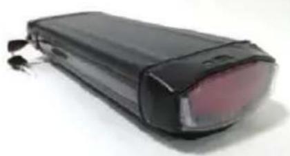
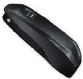
CARRIER / RACK batteries
natural_image
Black handheld electronic device with visible lens and ports (no text or symbols)
natural_image
Exterior view of a modern office building (no signage)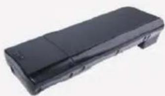
natural_image
Black rectangular electronic device with a flat top and side panel (no visible text or symbols)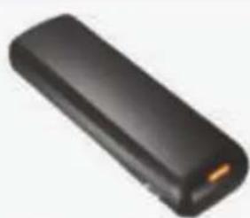
natural_image
Black rectangular electronic device with a gold connector (no visible text or symbols)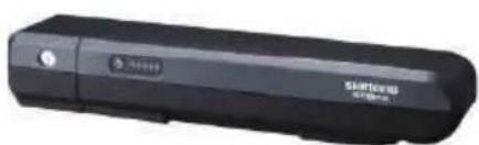
natural_image
Black rectangular electronic device with a circular button and 'STARTER' branding (no visible text beyond branding)Model: DEVRON ELECTRIC
Voltage: 36V
Capacity: 8.8Ah/11Ah/14.5Ah
BMS: Standard/Smart
Size Lxlxh (without
docking): 368mmX148mmX62mm
Charging cycles: Cca. 1000@100%
Weight: <3.2kg
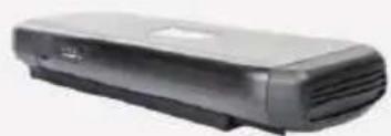
Model: WALLE-S
Voltage: 36V
Capacity: 16Ah/13Ah/14Ah
BMS: Standard/Smart
Size Lxlxh (without
docking): 375mmX150mmX64.5mm
Charging cycles: cca 1000 @100%
Weight: <4.5kg
Model: TT15
Voltage: 36V
Capacity: 8.8Ah/11.6Ah
BMS: Standard/Smart
Size Lxlxh (without
docking): 320mmX148mmX53mm
Charging cycles: cca 1000 @100%
Weight:: <3.2kg
Model: BT C01.340.UART
Voltage: 36V
Capacity: 14Ah
BMS: Standard/Smart
Size Lxlxh (without
docking): 408mmX123mmX70mm
Charging cycles: cca 1000 @100%
Weight:: 3KG
Model: Shimano BT E-6000
Voltage: 36V
Capacity: 11,6Ah (418Wh)
BMS: Smart
Size Lxlxh (without
docking): /
Charging cycles: cca 1000 @100%
Weight: 2,55KG
DOWNTUBE batteries
natural_image
Black office phone receiver with a flat case (no visible text or symbols)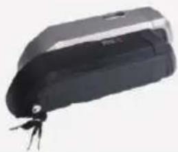
natural_image
Black and white photo of a handheld electronic device with a small key (no visible text or symbols)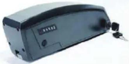
natural_image
Exterior view of a black electronic device with ports and connectors (no visible text or symbols)DOWNTUBE Integrated batteries
natural_image
Blue battery pack with red and black wires, no visible text or symbolsModel: Shimano BT E-6000 DT
Voltage: 36V
Capacity: 11,6Ah (418Wh)
BMS: Smart
Size Lxlxh (without
docking): /
Charging cycles: cca 1000 @100%
Weight: 2,6KG
Model: SF-06S
Voltage: 36V
Capacity: 11.6Ah/14Ah
BMS: Standard/Smart
Size Lxlxh (without
docking): 296.5mmX85mmX94mm
Charging cycles: cca 1000 @100%
Weight: <2.9kg
Model: DT-09
Voltage: 36V
Capacity: 11Ah/14.5Ah
BMS: Standard/Smart
Size Lxlxh (without
docking): 350mmX88mmX105mm
Charging cycles: cca 1000 @100%
Weight: <3.3kg
Model: DT-09
Voltage: 36V
Capacity: 11Ah/14.5Ah
BMS: Standard/Smart
Size Lxlxh (without
docking): 350mmX88mmX105mm
Charging cycles: cca 1000 @100%
Weight: <3.3kg
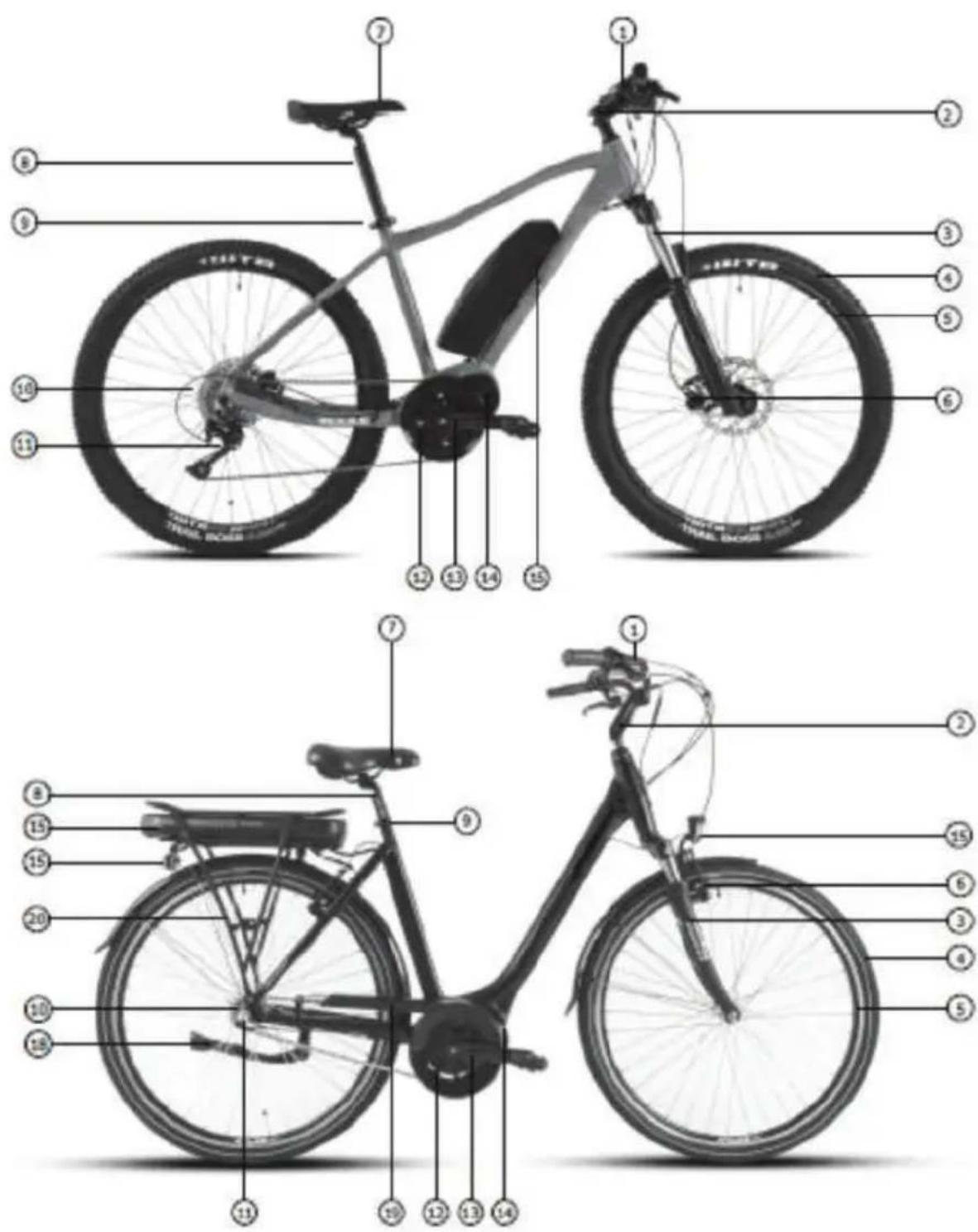
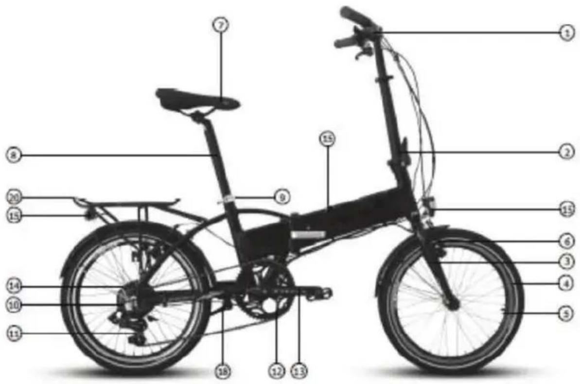
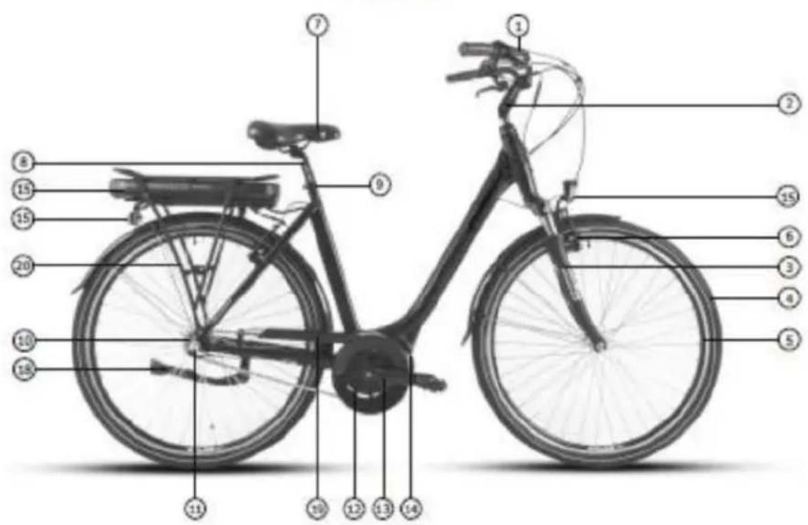
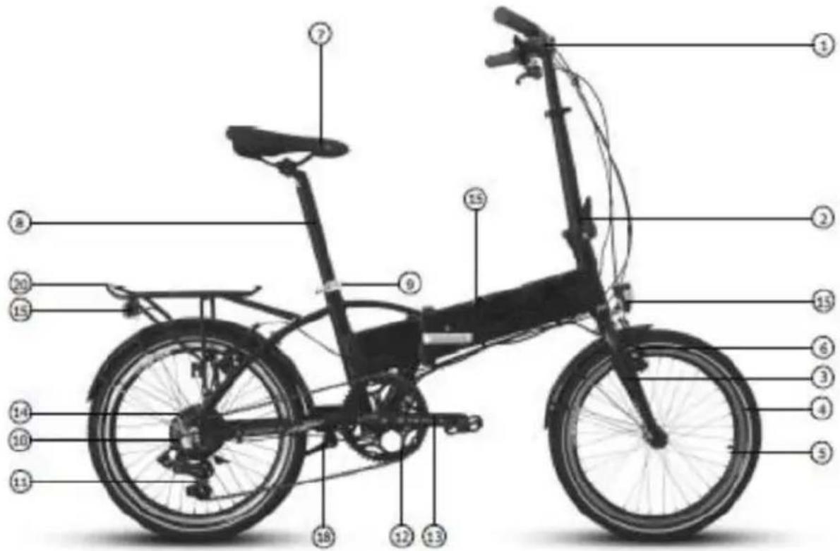
- Ebikehandlebar with control display, brake levers, shifters
- Stem (fixed, adjustable or foldable depending on model)
- Fork (suspension or fixed depending on model)
- Tire
- Wheel
- Brakes (vbrake or disc hidraulic depending on model)
- Saddle
- Seat post
- Quickrelease for saddle height adjustment (lever or nut)
- Mutispeed cassette or single sproket depending on model
- Rear derailleur / Front derailleur / Hub gear
- Single, double or triple chainwheel (depending on the model)
- Pedal arm with pedal
- Ebike motor (front wheel motor, midmotor or rear wheel motor)
- Ebike rechargeable battery (rack mout, downtube mount or integrated in frame)
- Light system or reflectors (depending on the model)
- Frame folding mechanism (depending on the model)
- Bicycle stand (depending on the model)
- Chainguard
- Carrier
COMMISSIONING – FIRST USE
Your ebike is delivered in preinstalled condition for shipping reasons.
Depending on the model supplied, not all parts and screws will be adjusted or tighten.
If not specified otherwise or your dealer has not made these operations prior purchase, your Ebike requires a few set ups before use as follows:
- All protection poly bags, wraps, light adhesive straps and plastic nut covers (located on both hub nuts) must be removed. Their sole purpose is to protect the ebike during shipment.
• Before the first use please charge the battery with the enclosed charger,
• Regardless of the battery level, so it will have a full charging cycle.
• Check the brakes (incl. tightness) functionality. - Handlebar and stem require adjustment and screws tightened accordingly since they are rotated for shipping purposes.
- Seat height should be adjusted according to your height and the seat clamp/nut tightened.
• Headlight should be adjusted for use.
• Pedals have to be mounted and tightened. - Check tire pressure and inflate according to tire indication if required.
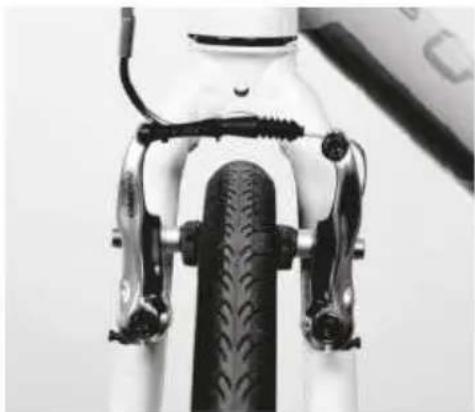
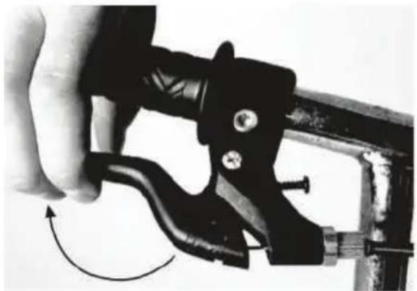
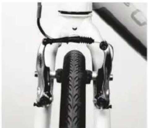
BRAKES CHECK
Check brake optimal function by applying force on the brake lever until half stroke (Pic.1). At this stage the brake pads should be firmly pressed against the rim surface (Pic.2).
natural_image
Close-up of a hand holding a black mechanical clamp or tool, with a curved arrow indicating rotation (no text or symbols visible)Pic.1
natural_image
Close-up of a bicycle front panel with black brake clips and a visible tire (no text or symbols)Pic.2
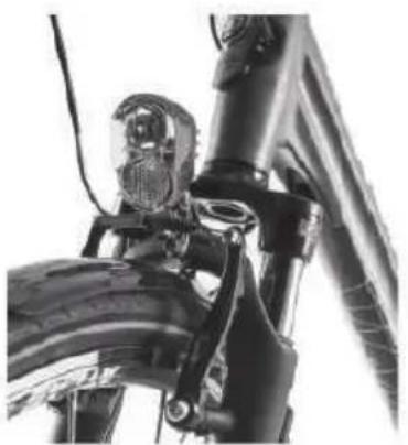
For optimum braking, the brake pads must be aligned and pressed against the rim surface with their entire length (Pic.3).
When the brake lever is released the brake pads should clear away from the rim surface. The clearance between the brake pads and rim should be equal on both sides. The brake pads and rim braking surface should be regularly checked for wear.
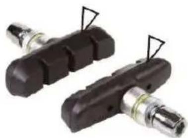
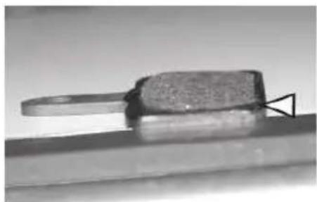
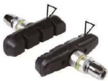
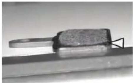
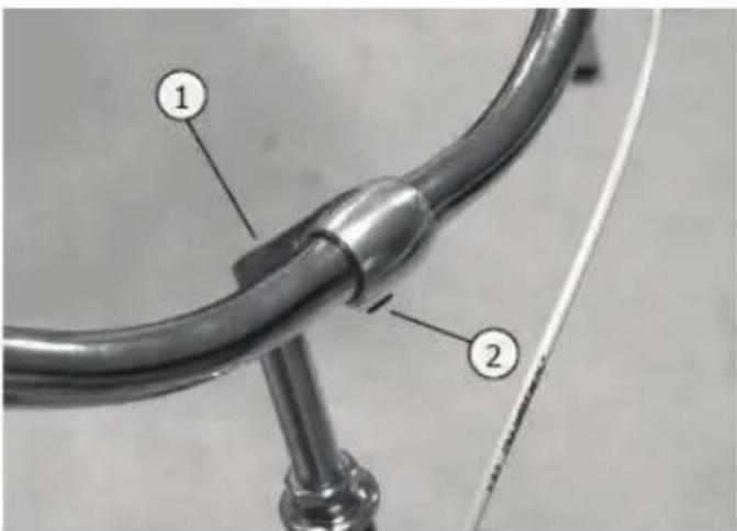
To inspect the brake pads for wear, slide back the cable protector and press inwards on both brakes to pull out the "J" guide from the clamp. In this moment the brake coils should push both brakes outward showing the brake pads surface. Brake pads have wear indicators carved on the brake surface. As long as these carvings are visible, the brake pads do not require to be replaced (Pic.4).
natural_image
Close-up of a bicycle's front wheel and suspension bracket (no visible text or symbols)Pic.3
natural_image
Two black mechanical components with attached metal fittings, no visible text or symbolsPic.4
natural_image
Close-up of a metallic tool or component with a textured surface and a triangular base, resting on a flat surface (no visible text or symbols)Pic.5
After inspection push both brakes inwards and connect the J guide. Slide the cable protector back.
HANDLEBAR, STEM AND ADJUSTMENTS
RIGID HANDLEBAR STEM
Loosen the clamp bolt no.1 and set the handlebar stem POSITION and HEIGHT.
Tighten the clamp bolt again. Loosen the clamp spindle screw no.2 and adjust the inclination angle of the handlebar. Tighten the bolt screw again.
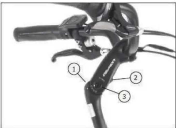
STEM WITH ANGLE ADJUSTMENT
Loosen the bolt no.1 and set the handlebar stem POSITION and HEIGHT. Tighten the bolt again according to the torque specification.
Loosen screw no.2 until blocking plate becomes loose from the grooves. Loosen the lateral clamp screw no.3. Adjust angle of the stem and tighten bolt no.2 until safety plate blocks in the grooves. Then tighten the bolt no.3 again according to the torque specification.
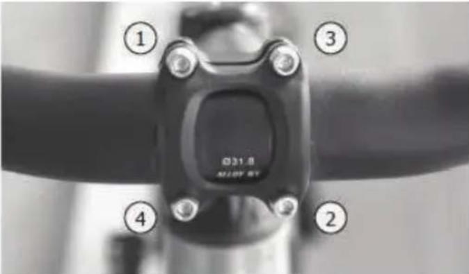
HANDLEBAR INCLINATION
Loosen the 4 bolts and adjust the inclination ANGLE of the HANDLEBAR. Tighten the bolts in the order shown, 1 to 4.
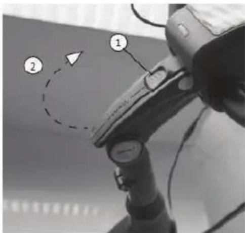
CLAMP ADJUSTMENT STEM
Push the no.1 button up to release the adjustment clamp release the clamp by pulling it up (2) adjust the STEM ANGLE block the stem by pulling the clamp down on lock position (3).
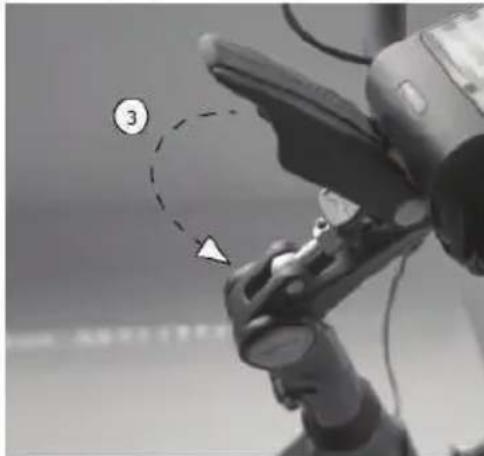
natural_image
Close-up of a robotic arm with a numbered callout (3) and a dashed circle highlighting a specific point, no readable text or symbols present.FOLDING STEM
To FOLD the handlebar push the no.1 button up to release the clamp pull down the clamp (2) fold over the handlebar (3) to adjust the HEIGHT of the handlebar release the quick clamp at the stem and set the handlebar to best fit your position (4).
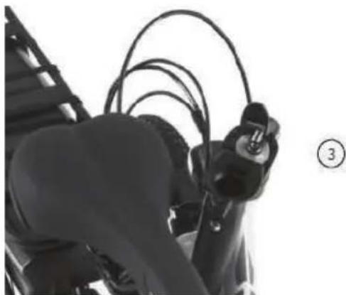
natural_image
Close-up of a person's torso and arm holding a black cable, with no visible text or symbols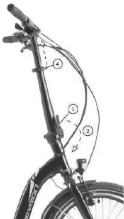
SADDLE AND ADJUSTMENTS
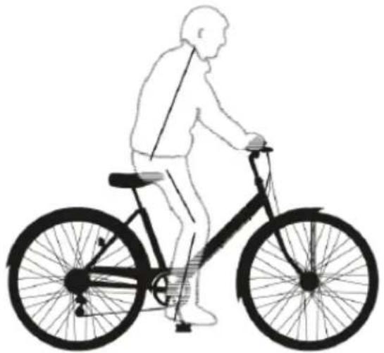
SEAT HEIGHT
The maximum permitted total weight must not exceed 150kg. The person using the bike should be able to keep balance and control the direction of movement and speed by braking/pedaling.
ADJUSTING THE SADDLE
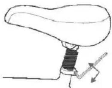
SEAT HEIGHT means the distance between the top surface of the saddle and pedal down position. The seat height is properly adjusted when the knee is bent slightly so that your foot rests on the pedal (low position) (Pic. 1). To modify the saddle height loosen the bolts (Pic.2) or release the lever in case of a quick release with clamp.
natural_image
Silhouette of a person riding a bicycle, no text or symbols presentPic. 1
natural_image
Line drawing of a mechanical lever mechanism with no text or symbolsPic. 2
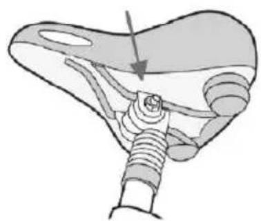
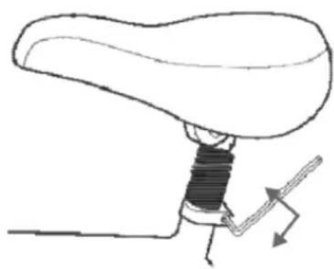
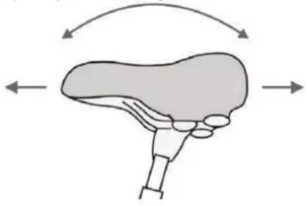
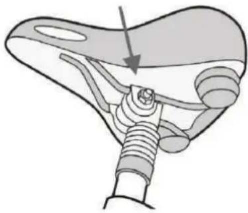
You also have the option to adjust the saddle tilt and foreaft positions (Pic. 3). To do this, loosen the bolt(s) using a spanner or allen key, located under the saddle (Pic.4). Adjust to required position and tighten the nut.
natural_image
Diagram of a liver with directional arrows indicating movement or force (no text or labels)Pic. 3
natural_image
Anatomical illustration of a mechanical joint or connector with a threaded rod and arrow indicating direction (no text or labels present)Pic. 4
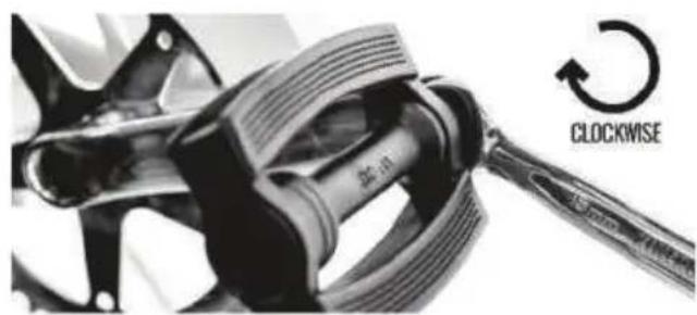
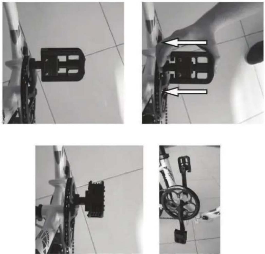
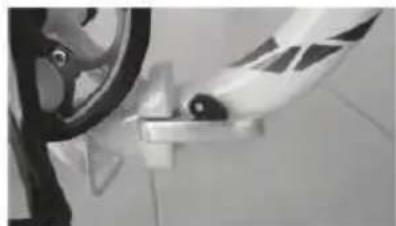
PEDALS
INSTALLING PEDALS
Identify left and right pedal: there are L" and "R" markings on the axles (threaded part that looks like a screw). Apply a small amount of grease.
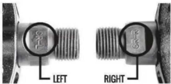
Install the LEFT pedal first. Rotate counterclockwise as threading is reversed compared to normal. Tighten hard but without extra force.
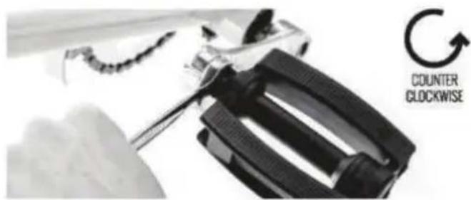
Install the RIGHT pedal next. Rotate clockwise. Tighten hard but without extra force.
LIGHTS SYSTEM
The headlight and tail light are powered by the rechargeable battery. Always using your lights will add to your safety since you can also be spottet when stopped. If the electric drive system switches off because the battery is discharged, you will still be able to use the lights for at least 1 hour.
To switch the lights ON and OFF, push the following buttons, depending of your control display:


If your ebike is not equipped with lights, these buttons will turn ON and OFF the control screen backlight.
WHEELS
The maximum permitted total weight must not exceed 150kg. The person using the bike should be able to keep balance on the bike and be able to control the direction of movement and speed by braking / pedaling.
A wheel consists of:
- Hub;
- Sprocket or cassette (on rear wheel hub);
- Brake disk (if fitted);
- Spokes and nipples;
- Rim;
- Tire;
- Tube (not present on Tubeless rims);
- Rim tape insert;
Wheels have several dimensions:
26 inch - rim diameter 559mm+tyre 27,5 inch - rim diameter 584mm+tyre 29 inch - rim diameter 622mm+tyre
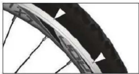
RIMS
The rims should not have dirt of any kind. Grease if identified, remove immediately. Make visual checks of rim wear level and if exceeded, replace imediately. (Pic.2).
Pic.1
natural_image
Close-up of a bicycle wheel rim with visible tire and spokes (no text or symbols)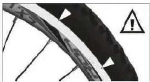
natural_image
Close-up of a bicycle tire with warning symbol (no text or labels)Pic.2
TIRES
The valve must be in radial position (meaning that is oriented towards the hub). Check air pressure and use a pump to inflate if necessary. The tire pressure intervals can be found on the tire sides.
Please consult a mechanic or bicycle shop on how to interpret these readings.
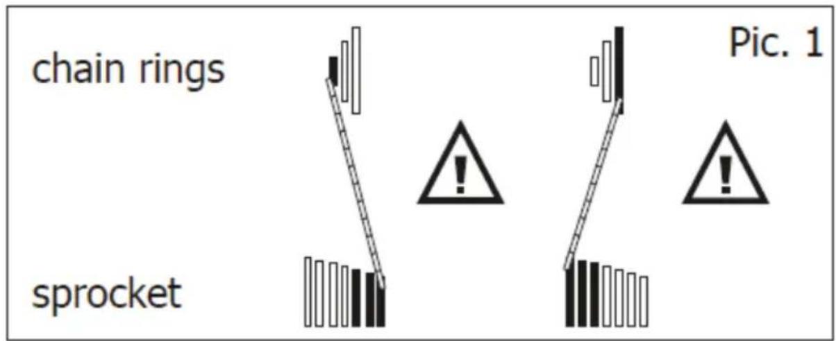
Shifting gears means moving the chain up and down from sprocket to sprocket or chainring to chainring by operating the shifters.
It is not recommended to use the largest chainring with the largest sprocket or the smallest chainring with the smallest sprocket.
Note! Do not shift the position of the chain from one chainring to another and from one sproget to another in the same time during use as you will risk damaging the chain and transmission parts.
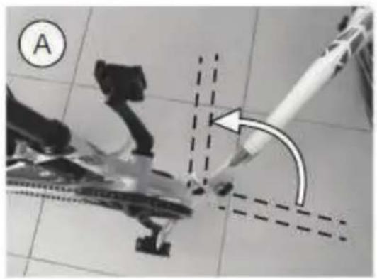
FOLDING E-BIKE
FOLDING OPERATION INSTRUCTIONS
Fold the pedals by pushing the pedal towards the chainwheel.
Unlock the safety and pull the quick clamp to open fully.
natural_image
Close-up of a bicycle wheel and attached bracket (no visible text or symbols)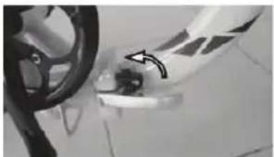
natural_image
Close-up of a car wheel and dashboard with a hand pointing to a component (no visible text or symbols)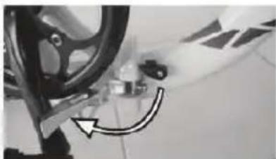
natural_image
Close-up of a bicycle wheel and gear assembly with a curved arrow indicating motion (no text or symbols visible)A. Fold the frame at 90 degrees from original position.
B. Completely lower the handlebar using the Quick Release Lever (QR).
C. Open the quick lever and unlock the blocking pin.
D. Fold the handlebar all the way down and then completely fold the ebike frame.
natural_image
Close-up of a robotic arm with a tool interacting with a mechanical component, no visible text or symbols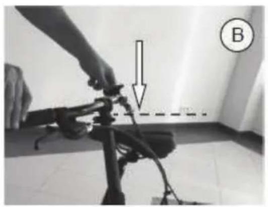
natural_image
Person adjusting a mechanical device with a downward arrow and dashed line, labeled B (no text or symbols on the device itself)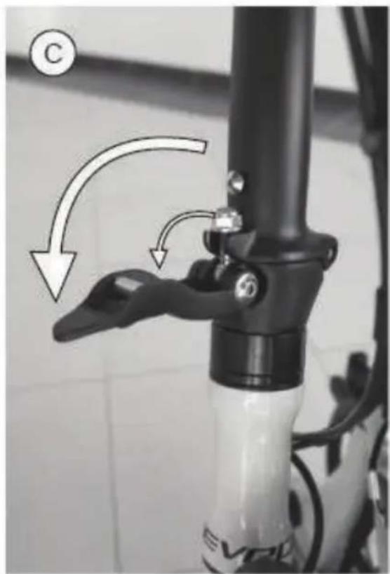
natural_image
Close-up of a bicycle lever mechanism with directional arrows indicating motion (no text or symbols)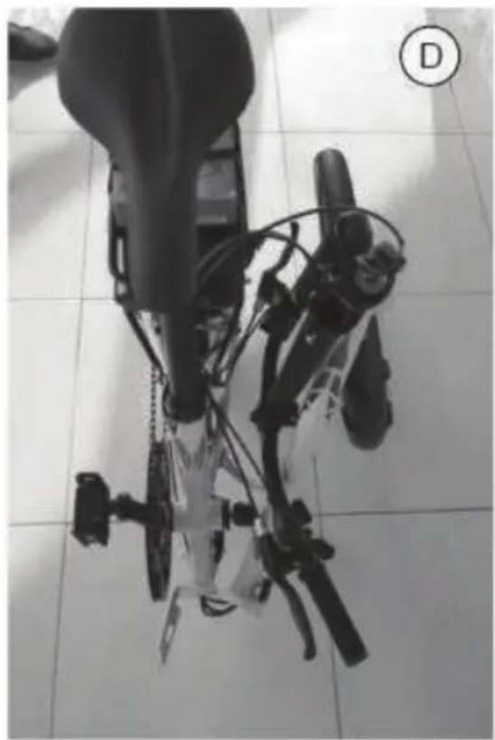
natural_image
Top-down view of a robotic device with visible wiring and mechanical components, placed on tiled floor (no text or symbols)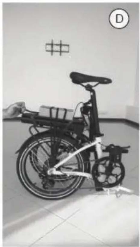
natural_image
Black-and-white photo of a bicycle with a hand adjusting its seat, displayed indoors near a wall with a grid pattern and a circular symbol (D) in the corner.DP E06 LED CONTROL DISPLAY
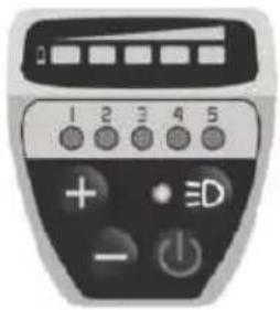
The LED control display operates the drive system and is located on the handlebar on the left side, near the grip.
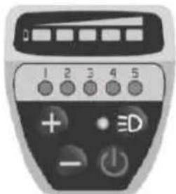
1. Control Unit Function Overview

2. Operations
2.1 Power button ON/OFF
Push Power On/Off button for 2 seconds to switch on/off the LED control unit and electric drive system.
The system will automatically turn off if left idling for more than 5 minutes.
2.2 Pedal assistance (PAS) level selection
Once turned on, the system switches todefault Level 0.
Push "+" or "-" buttons to switch between different levels of assistance. The LED light on top of each number indicates the level of assistance selected.
If there is no LED light indication, it means you are on default mode or have selected Level 0 and the electric system does not offer any assistance. The ebike behaves similar to a standard bike. You will feel the electric assistance kicking in once selecting again between Levels 1 up to 5.
2.3 Light ON/OFF
With the display switched on, press the button for 2 seconds to turn on/off the headlight and taillight.
2.4 Walk Assist Function
The ebike comes equipped with walk assist function.
This feature propels forward your ebike with a constant speed of 6 km/h without pedaling and requires to hold ti balanced when walking along side it. It comes very handy when needing to push it up a steep incline.
Hold the "-" button to activate the walk assist.
This function remains activated as long as you keep hold on the "-" button and deactivates the moment you stop holding it.
2.5 Battery charge level
The LED bar on top will be completely lit if the battery is fully charged and the LED indicators will gradually switch off when the battery charge level starts dropping.
DP E12 LED CONTROL DISPLAY
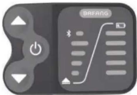
The LED control display operates the drive system and is located on the handlebar on the left side, near the grip.
1. Control Unit Function Overview
2. Operations
2.1 Power button ON/OFF
Push power on/off button for 2 seconds to switch on/off the LED control unit and electric drive system.
The system will automatically turn off if left idling for more than 5 minutes.
2.2 Pedal assistance (PAS) level selection
Push "+" or "-" buttons to switch between different levels of assistance. The LED light on top of each number indicates the level of assistance selected. If there is no LED light indication, it means you are on default mode or have selected Level 0 and the electric system does not offer any assistance.
The ebikebehaves similar to astandard bike. You will feel the electric assistance kicking in once selecting again between Levels 1 up to 4.
2.3 Lights Button ON/OFF
With the display switched on, hold the button for 2 seconds to turn on/off the headlight and taillight.
2.4 Walk Assist Function
The ebike comes equipped with walk assist function. This feature propels forward your ebike with a constant speed of 6km/h without pedaling and requires to hold it balanced when walking along side it. It comes very handy when needing to push it up a steep incline.
Hold the button to activate the walk assist.
This function remains activated as long as you keep hold on the button and deactivates the moment you stop holding it.
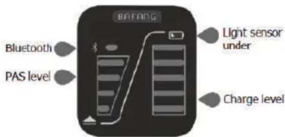
2.5 Bluetooth connection
The control display unit connects with your Android smartphone via Bluetooth and uses BAFANG GO application to collect data. The display is also equipped with charging port for your mobile device. BAFANG GO is available for download on Google Play.
2.6 Battery charge level
The LED bar on top will be completely lit if the battery is fully charged and the LED indicators will gradually switch off when the battery charge level starts dropping.
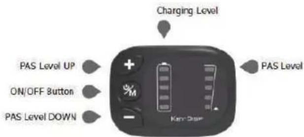
KD59E LED CONTROL DISPLAY
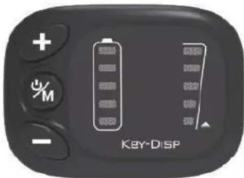
The LED control display operates the drive system and is located on the handlebar on the left side, near the grip.
1. Control Unit Function Overview
2. Operations
Push 📋 button for 2 seconds to switch on/off the LED control unit and electric drive system.
The system will automatically turn off if left idling for more than 5 minutes.
2.2 Pedal assistance (PAS) level selection
Once turned on, the display switches to default Level 1.
Push "+" or "-" buttons to switch between different levels of assistance. The LED light on top of each number indicates the level of assistance selected.
If there is no LED light indication, it means you are on default mode or have selected Level 0 and the electric system does not offer any assistance. The ebike behaves similar to a standard bike. You will feel the electric assistance kicking in once selecting again between Levels 1 up to 5.
2.3 Lights Button ON/OFF
With the display switched on, hold the "+" button for 2 seconds to turn on/off the headlight and taillight.
2.4 Walk Assist Function
The ebike comes equipped with walk assist function. This feature propels forward your ebike with a constant speed of 6km/h without pedaling and requires to hold it balanced when walking along side it. It comes very handy when needing to push it up a steep incline.
Hold the "-" button to activate the walk assist. This function remains activated as long as you keep hold on the "-" button and deactivates the moment you stop holding it.
2.5 Battery charge level
The LED bar on top will be completely lit if the battery is fully charged and the LED indicators will gradually switch off when the battery charge level starts dropping.
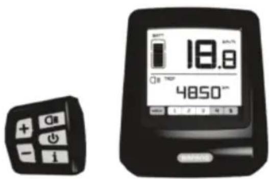
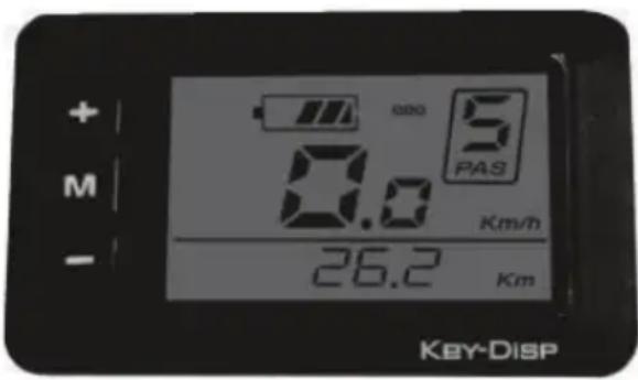
DP C10 LCD CONTROL DISPLAY
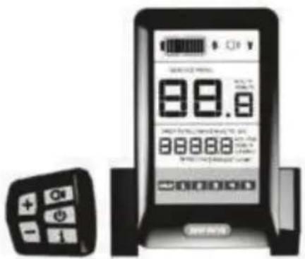
The control unit operates the LCD display and the drive system and is located on the handlebar in the left side, near the grip. The LCD display unit is located in the middle of the handlebar.
1. Control Unit Function Overview
2. Control Unit Function Overview
2.1 Power Button ON/OFF
Hold "D" button for 2 seconds to switch on/off the LED control unit and electric drive system.
The system will automatically turn off if left idling for more than 5 minutes.
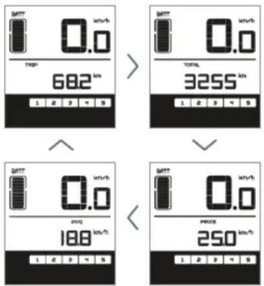
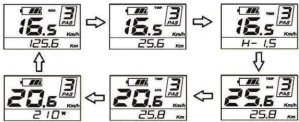
2.2 Toggle between display modes
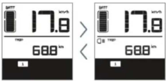
Press "E" button to toggle between distance and speed modes. Follow the LCD display indication: singletrip distance (TRIP km), total distance (TOTAL km), maximum speed (MAX speed), range left (RANGE) and energy consumption (C).
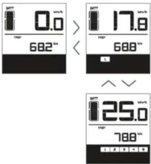
2.3 Assist mode
Push "A" or "B" buttons to select the desired assist level for electric system. The lowest is Level 1 and the highest is Level 5. When powered on, the default is Level 1. When there is no numeric power level displayed it means the ebike is in park or it functions as a standard bike with no assist from the motor.
You will feel the electric assistance kicking in once selecting again between Levels 1 up to 5.
2.4 Lights/Backlight Button ON/OFF
With the display switched on, had the "C" button for 2 seconds to turn on/off the headlight, taillight and the display backlight.
NOTE! If the display is powered on in a darkenvironment the headlight, taillight and display backlight will be turned on automatically. If the display light is turned off manually it will require to be turned on manually afterwards.
2.5 Walk Asist
The ebike comes equipped with walk assist function. This feature propels forward your ebike with a constant speed of 6km/h without pedaling and requires nothing but to hold it balanced when walking along side it. It comes very handy when needing to push it up a steep incline.
Hold the "B" button to activate the walk assist.
This function remains activated as long as you hold the button and deactivates the moment you stop holding it.
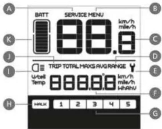
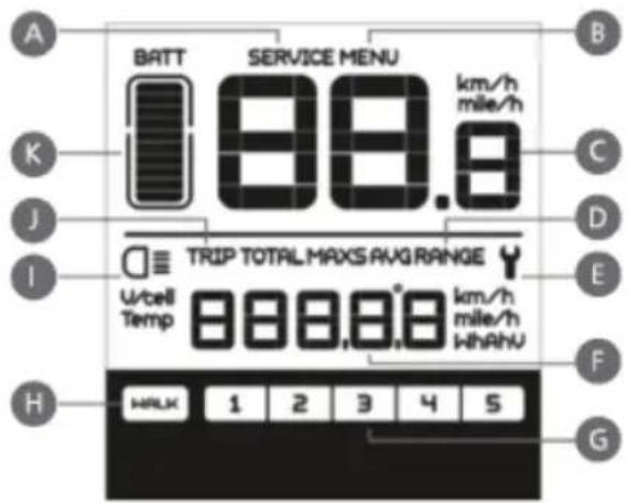
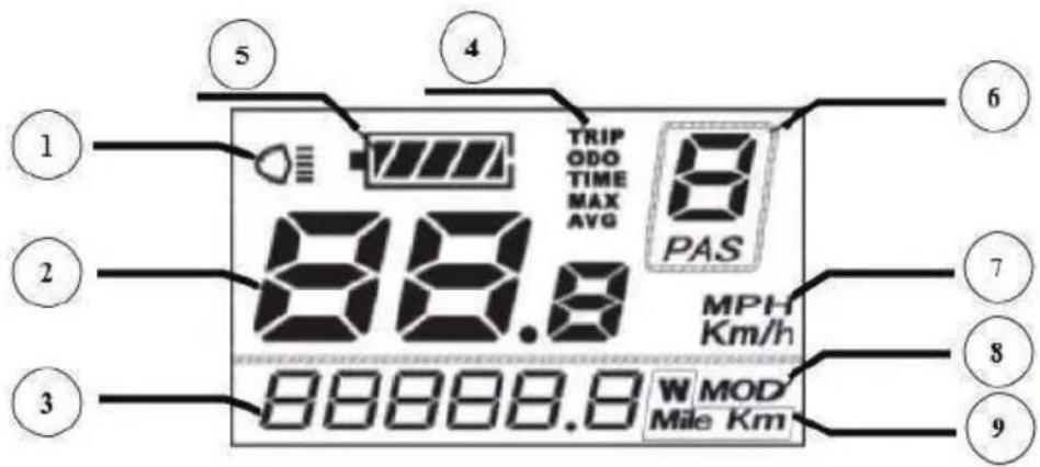
3. LCD control display
The LED display is located on the middle of the handlebar and represents the system's interface of "communication" with the user.
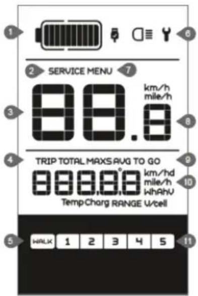
1 Battery level
2 Maintenance warning
3 Headlight indication
4 Distance mode
5 Asistance
6 Malfunction indication
7 Menu
8 Speed display
9 Speed model
10 Distance indication
11 Level indication
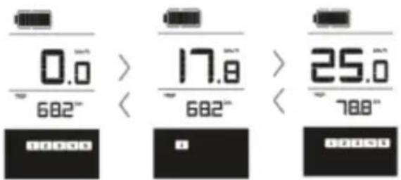
3.1 Display messages
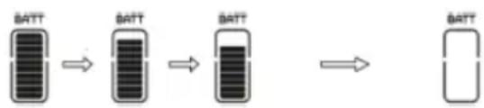
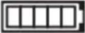
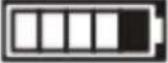
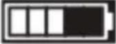
- Battery status indicator: when the battery is completely charged all the LED segments as well as the segments border are lit up, segments gradually going off as the battery depletes during use. If all the 10 segments are off and the border is intermittent, the battery needs to be charged immediately.
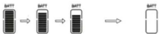
flowchart
graph LR
    A["BATT"] --> B["BATT"]
    B --> C["BATT"]
    C --> D["BATT"]
Display
10 segments
9 segments
8 segments
7 segments
6 segments
5 segments
4 segments
3 segments
2 segments
1 segments
Intermittent border
Battery Level
90% to FULL capacity
80% to 90% capacity
70% to 80% capacity
60% to 70% capacity
50% to 60% capacity
45% to 50% capacity
35% to 45% capacity
25% to 35% capacity
15% to 25% capacity
5% to 15% capacity
under 5% capacity
-
Maintenance Warning information is displayed based on the battery charge cycles and riding distance. The system automatically estimates the battery life and gives warnings when the number of charge cycles has exceeded the battery life. A warning light will also come on when the total riding distance exceeds the motor life cycles.
-
Headlight Indication only appears when the lights/backlight are on.
- Distance Mode shows the maximum speed MAX, average speed AVG, singletrip distance TRIP, total distance TOTAL, remaining range TO GO, power W, consumed energy C.
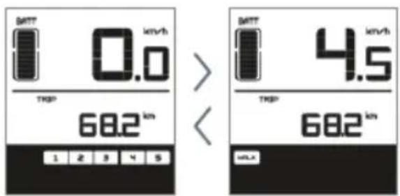
- Walk Assist if user selected, the {xxx} icon will be displayed.
- Malfunctions Indicator will come on when an error is detected. Visit your dealer or a service workshop in your vicinity.
- Menu Display
-
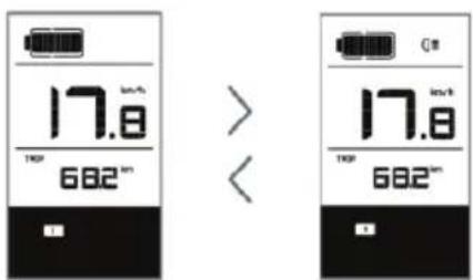
Speed Display – shows the current traveling speed in km/h or mph depending on user selection.
-
Indicates Km/h or Mph.
- Range – displays the range depending on the settings.
- Assistance Level displays the level of assist from 1 to 5 selected by user. If no numeric icon is displayed, means the ebike is either on park, idle or user selected Level 0 with no assistance from the motor and the ebike behaves as a standard bike. You will feel the electric assistance kicking in once selecting again between Levels 1 up to 5.
The LCD display unit can charge your mobile device. With the display turned off, connect to the USB port and then turn on the LCD unit to commence charging. If the display is already on, connect to the USB port to commence charging. Maximum charge voltage is 0.5A.
ERROR Code Definitions most common FAULT codes are listed below to draw your attention to issues needing to be addressed by a specialized shop and no attempts to fix shall be done except by a trained technician.
ERROR Code Definitions
| Error Code | Error Definition | Repair Solution |
| “07” | Power Surge | Check battery voltage |
| “08” | Motor Signal Cable Fault | Check the motor module |
| “09” | Motor Phase Cable Fault | Check the motor module |
| “11” | Controller Temperature Sensor Fault | Check the controller |
| “12” | Current Sensor Failure | Check the controller |
| “13” | Battery Temperature Fault | Check the battery |
| “14” | Motor Temperature Fault | Check the motor |
| “21” | Speed Sensor Fault | Check position of speed sensor |
| “22” | BMS Communication Fault | Replace the battery |
| “30” | Communication Fault | Check the controller connection |
NOTE! Various parameters of the LCD display can be set with a computer via a communication cable. Certain features listed above may not have been set on your ebike depending on the model or optional features.
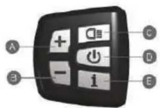
DP C07 LCD CONTROL DISPLAY
The control unit operates the LCD display and the drive system and is located on the handlebar in the left side, near the grip. The LCD display unit is located in the middle of the handlebar.
1. Control Unit Function Overview
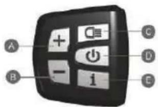
A. Increase Assist level.
B. Decrease Assist level.
C. Lights On/Off.
D. System's power ON/OFF.
E. Other functions.
1.1 Power Button ON/OFF
Hold "D" button for 2 seconds to switch on/off the LED control unit and electric drive system.
The system will automatically turn off if left idling for more than 5 minutes.
1.2 Toggle between display modes
Press "E" button to toggle between distance and speed modes. Follow the LCD display indication: singletrip distance (TRIP km), total distance (TOTAL km), maximum speed (MAX speed), range left (RANGE) and energy consumption (C).
1.3 Assist mode
Push "A" or "B" buttons to select the desired assist level for electric system. The lowest is Level 1 and the highest is Level 5. When powered on, the default is Level 1. When there is no numeric power level displayed it means the ebike is in park or it functions as a standard bike with no assist from the motor.
You will feel the electric assistance kicking in once selecting again between Levels 1 up to 5.
1.4 Lights/Backlight Button ON/OFF
With the display switched on, hold the "C" button for 2 seconds to turn on/off the headlight, taillight and the display backlight.
NOTE! If the display is powered on in a darkenvironment the headlight, taillight and display backlight will be turned on automatically. If the display light is turned off manually it will require to be turned on manually afterwards.
1.5 Walk Asist
The ebike comes equipped with walk assist function. This feature propels forward your ebike with a constant speed of 6km/h without pedaling and requires nothing but to hold it balanced when walking along side it. It comes very handy when needing to push it up a steep incline.
Hold the "B" button to activate the walk assist.
This function remains activated as long as you hold the button and deactivates the moment you stop holding it.
2. LCD control display
The LED display is located on the middle of the handlebar and represents the system's interface of "communication" with the user.
A. Maintenance Warning symbol is displayed based on the battery charge cycles and riding distance. The system automatically estimates the battery life and gives warnings when the number of charge cycles has exceeded the battery life. A warning light will also come on when the total riding distance exceeds the motor life cycles.
B. Menu
C. Displays the current traveling speed in km/h or mph depending on user selection.
D. Displays average speed AVG and maximum speed MAXS.
E. Error display will come on when an error is detected. Visit your dealer or a service workshop in your vicinity.
F. Distance indication: display of the distance depending on the setting.
G. Assistance Level displays the level of assist from 1 to 5 selected by user. If no numeric icon is displayed, means the ebike is either on park, idle or user selected Level 0 with no assistance from the motor and the ebike behaves as a standard bike.
You will feel the electric assistance kicking in once selecting again between Levels 1 up to 5.
H. Walk Assist [WALK] symbol displayed when walk assist function is activated.
I. Headlight/taillight/backlight symbol displayed when lights are on.
J. Displays single trip distance TRIP and total distance TOTAL.
K. Battery charge level indicator. When the battery is completely charged all the LED segments as well as the segments border are lit up, segments gradually going off as the battery depletes during use.
If all the 10 segments are off and the border is intermittent, the battery needs to be chargedimmediately.
flowchart
graph LR
    A["BATT"] --> B["BATT"]
    B --> C["BATT"]
    C --> D["BATT"]
Display
| 10 segments | 90% to FULL capacity |
| 9 segments | 80% to 90% capacity |
| 8 segments | 70% to 80% capacity |
| 7 segments | 60% to 70% capacity |
| 6 segments | 50% to 60% capacity |
| 5 segments | 45% to 50% capacity |
| 4 segments | 35% to 45% capacity |
| 3 segments | 25% to 35% capacity |
| 2 segments | 15% to 25% capacity |
| 1 segments | 5% to 15% capacity |
| Intermittent border | under 5% capacity |
ERROR Code Definitions
| Error Code | Error Definition | Repair Solution |
| “07” | Power Surge | Check battery voltage |
| “08” | Motor Signal Cable Fault | Check the motor module |
| “09” | Motor Phase Cable Fault | Check the motor module |
| “11” | Controller Temperature Sensor Fault | Check the controller |
| “12” | Current Sensor Failure | Check the controller |
| “13” | Battery Temperature Fault | Check the battery |
| “14” | Motor Temperature Fault | Check the motor |
| “21” | Speed Sensor Fault | Check position of speed sensor |
| “22” | BMS Communication Fault | Replace the battery |
| “30” | Communication Fault | Check the controller connection |
NOTE! Various parameters of the LCD display can be set with a computer via a communication cable. Certain features listed above may not have been set on your ebike depending on the model or optional features.
KD21C LCD CONTROL DISPLAY
The control unit is integrated with the LCD display and operates the drive system. It is located on the handlebar in the left side near the grip.
1. Control Unit Function Overview
1.1 Power Button ON/OFF
Hold the "M" button for 2 seconds to switch on/off the LED control unit and electric drive system.
The system will automatically turn off if left idling for more than 10 minutes.
1.2 Assist mode
Hold "+" or "-" buttons to select the desired assist level for electric system. The lowest is Level 1 and the highest is Level 5. When powered on, the default is Level 1. When there is no numeric power level displayed it means the ebike is in park or it functions as a standard bike with no assist from the motor. You will feel the electric assistance kicking in once selecting again between Levels 1 up to 5.
1.3 Lights/Backlit Button ON/OFF
With the display switched on, hold the "+" button for 2 seconds to turn on/off the headlight, taillight and the display backlight.
1.4 Walk Asist
The ebike comes equipped with walk assist function. This feature propels forward your ebike with a constant speed of 6km/h without pedaling and requires nothing but to hold it balanced when walking along side it. It comes very handy when needing to push it up a steep incline.
Hold the "-" button to activate the walk assist.
This function remains activated as long as you hold the button and deactivates the moment you stop holding it.
NOTE! Push Assist function should only be used when the wheels are in contact with the ground.
Danger of injury may occur if push assist function is activated since the wheel (front or rear depending on the motor loation) will start spinning.
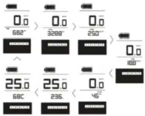
LCD Control Display Information
- Lights ON/OFF status.
- Current speed.
- Text Indication displays various codes including ERROR code. When ERR21 is displayed contact a Service Shop or your dealer immediately.
- Function List. When powered on, the system displays Running Speed, Total Distance, Battery Charge Level and Assist Level. To toggle between various information, press button to view: Instant Speed (km/h) > Trip Distance (km) > Trip Duration (Hours) > Maximum Speed reached (km/h) > Average Traveling Speed (km/h) > Motor Power Output (W) > Instant Speed (km/h).
- Battery charge level status indicator when the battery is completely charged all the LED segments as well as the segments border are lit up, segments gradually going off as the battery depletes during use. If all the 10 segments are off and the border is intermittent, the battery needs to be charged immediately.
- Assist Level indicator – displays the level of power assist in numerical indication from Level 0 to Level 5 depending on user's selection.
- Speed Units – shows Km/h or Mph depending on user selection. The system comes preset with km/h from the factory.
- Settings indicator
- Displays Range and power.
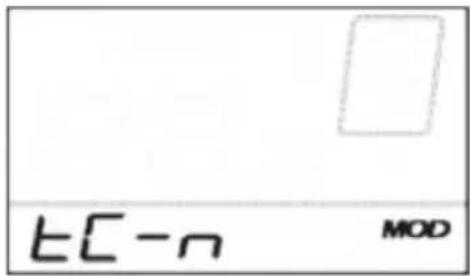
General Settings Menu
After the system is switched on, hold both "+" and "-" buttons for 2 seconds to access general settings menu.
TRIP DISTANCE reset TC icon is displayed.
Toggle between Y or N by pressing "+" and "-" buttons. Default value is N.
Press MODE (M) button to store settings and switch to contrast settings.
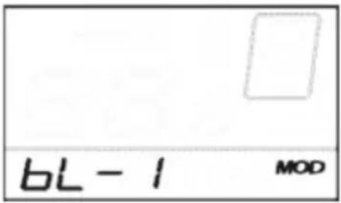
BACKLIGHT CONTRAST setting -
bL icon is displayed. Choose between Levels 1, 2 and 3 where 3 is maximum contrast. The default value is 1. Press "+" or "-" to toggle between various contrast levels.
Press MODE(M) button to store settings and switch to km/mile conversion settings.
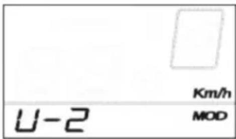
KM/MILE display conversion settings –
U icon is displayed. 1 stands for miles and 2 stands for kilometer. The default value is 2.
Press +/- buttons to select desired mode. To store changes press MODE button to store settings. The system will take you back to trip distance reset.
To exit general settings menu hold MODE (M) button for 2 seconds..
Trip Distance Clearance Settings Interface
Backlight Brightness Settings Interface
Mile and Kilometer Conversion Settings Interface

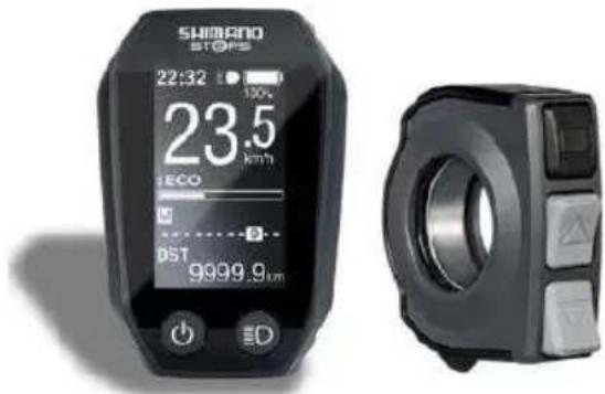
SHIMANO STEPS SCE 6010 AND SCE 6000 UNITS
Features
- High shifting performance system (In the case of electronic gear shifting) This system uses accurate sensors to enable shifting gears by providing the most appropriate level of power assistance carefully adjusted by computer controls.
- Full Automatic Shifting (In the case of electronic 8-speed gear shifting). The sensors detect riding conditions, whether you are riding up a hill against the wind, or on flat ground with no wind; the automatic gear shifting system uses computer controls to make your ride more pleasant.
- Start mode (In the case of electronic gear shifting. This function allows automatic shifting down to a preset gear when you stop the bicycle such as at traffic lights so that you can start traveling at a light gear.
- If, while the bicycle is stopped, you shift to a gear lower than the set gear, the system will not automatically shift up.
• Light off road Sporty, provides powerful assistance. Can only be used when set by the manufacturer of the completed bicycle.
• Walk assistance function (Walk assist mode)
• The Walk assist mode function may not be able to be used in certain regions. - Some of the functions listed above can only be used once the firmware has been updated. If this is the case, consult the place of purchase, and carry out the firmware updates.
Riding the bicycle
• Turn on the power.
- Do not place your foot on the pedals when turning the power on. A system error may result
• Power cannot be turned on while charging.
- Select your preferred assist mode.
- Assistance will start when the pedals start turning. Change the assist mode in accordance with the riding conditions.
• Turn the power off when parking the bicycle.
Do not place your foot on the pedals when turning the power off. A system error may result.
Assist mode
You can select a SHIMANO STEPS assist mode for each particular application.
HIGH NORMAL ECO
Use when powerful assistance is required, such as when riding up steep uphill slopes..
Use when an intermediate level of assistance is needed, such as when you want to enjoy riding comfortably on agentle slope or level ground.
Use when you want to enjoy long distance riding on level ground. When pedaling is not very strong, the amount of assistance is reduced and energy consumption is lessened.
When the bat tery level is running low, the level of assistance is lowered to increase the traveling range.
OFF Mode. This mode does not provide power assistance when the power is turned on. Since there is no power consumption associated with the power assistance, it is useful for reducing battery consumption when the battery is running low.
WALK Assist. This mode is particularly useful when you walk the bicycle with heavy baggage on it or walk it out of a basement. The Walk assist mode function may not be able to be used in certain regions Comutarea între operațiile ciclocomputerului și moduri
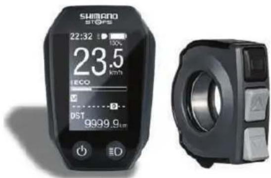
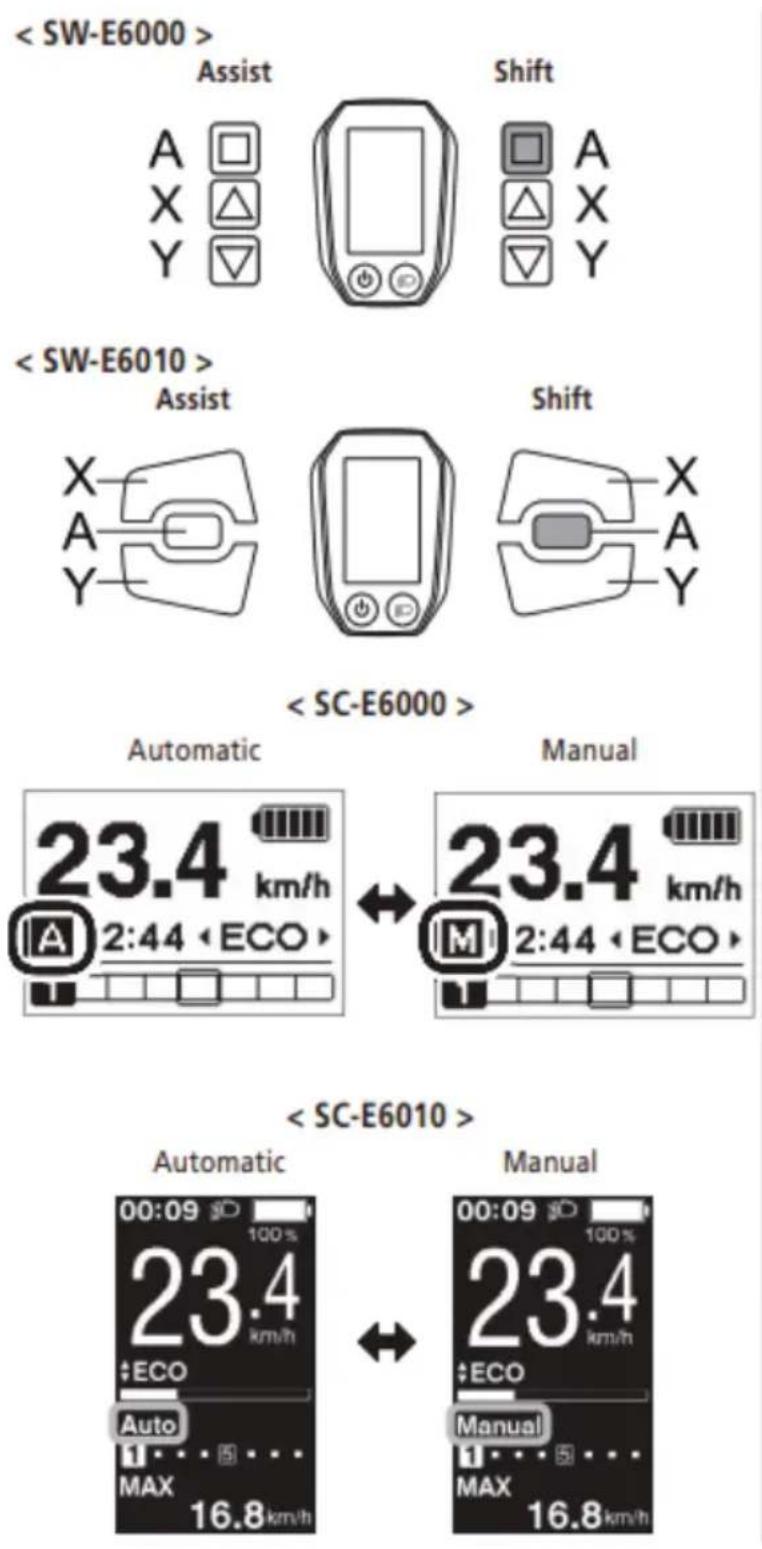
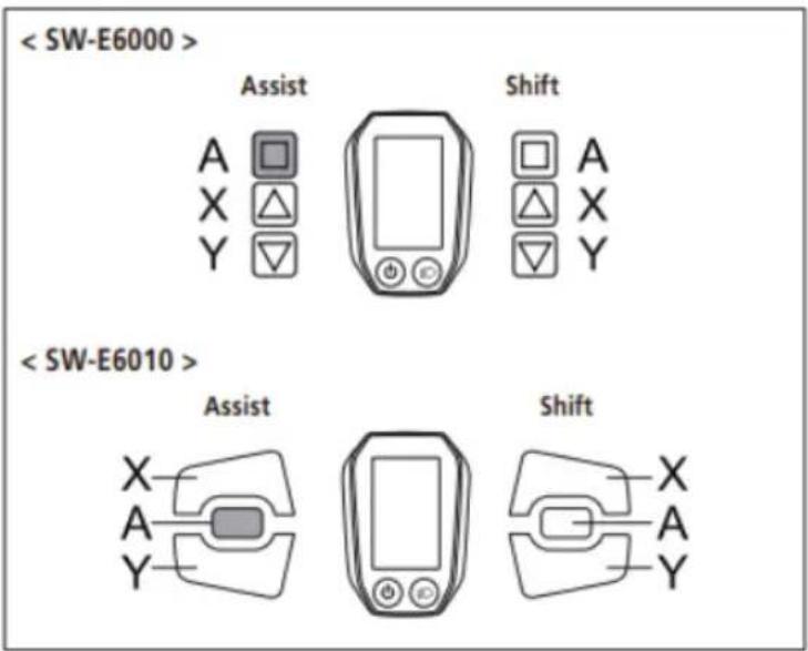
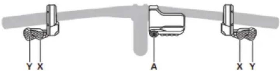
CONTROL DISPLAY
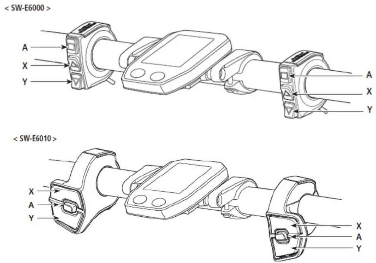
A Changing the cycle computer display
Switching between automatic and manual gear shifting
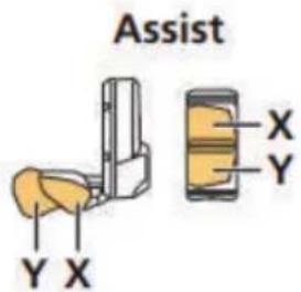
X When switching assist modes: the level of assistance becomes stronger
When shifting gears: pedaling becomes heavier
Y When switching assist modes: the level of assistance becomes weaker
When shifting gears: pedaling becomes lighter
The operation procedure provided here refers to cases where the cycle computer is set to the default values.
Installing and removing the cycle computer
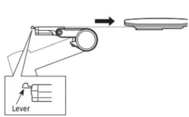
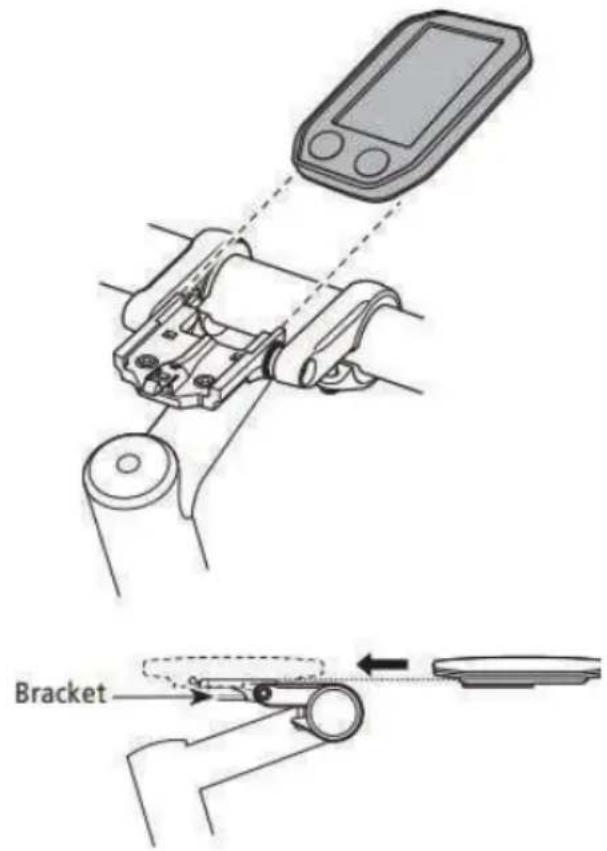
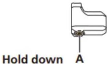
Slide the cycle computer onto the bracket as shown in the illustration to install it.
Insert the cycle computer securely until it clicks into place.
To remove the cycle computer, push the lever of the bracket firmly while sliding out the cycle computer.
If the cycle computer is not correctly in place, the assist function will not operate normally.
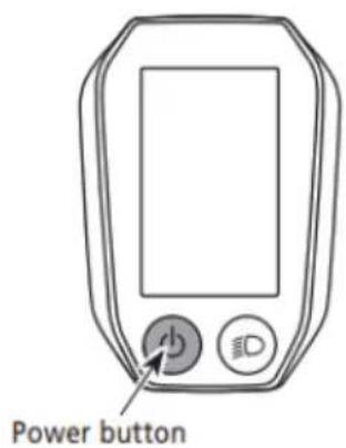
Turning the power ON / OFF
Automatic power off function
If the bicycle has not moved for over 10 minutes, the power will automatically turn off.
Turning the power ON and OFF via the cycle computer Hold down the power button on the cycle computer for 2 seconds.
If built-in battery of cycle computer isn't charged sufficiently, the power will not turn on.
The built-in battery of the cycle computer is charged only when the cycle computer screen is on
CONTROL DISPLAY
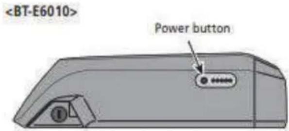
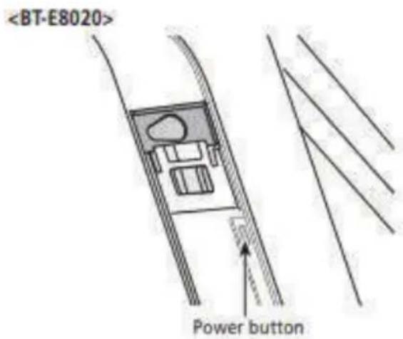
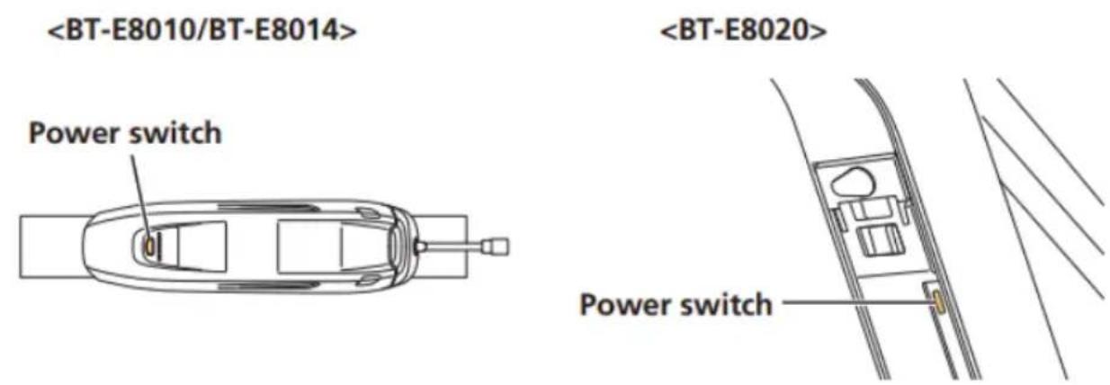
< BT-E6000/BT-E6001/BT-E6010/BT-E8010/BT-E8020 >
Turning the power ON and OFF via the battery
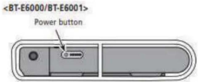
Press the power button on the battery. The LED lamps will light up indicating remaining battery capacity.
CAUTION
- When turning on the power, check that the battery is firmly attached to the holder.
• Power cannot be turned on while charging. - Do not place your foot on the pedals when turning on. A system error may result.
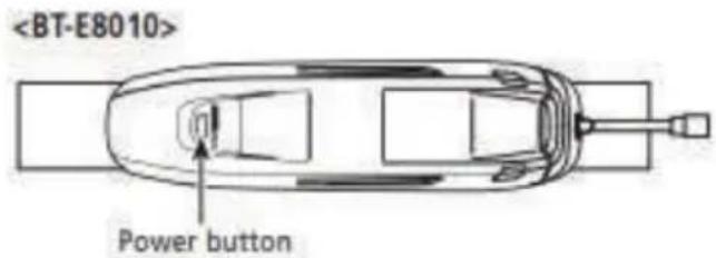
BT-E8010/BT-E8020 can be forced to power off by holding down the power button for 6 seconds.
SHIMANO STEPS logo screen
This screen is displayed during system start up and shutdown.
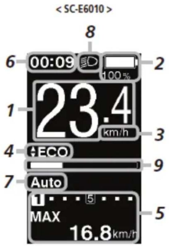
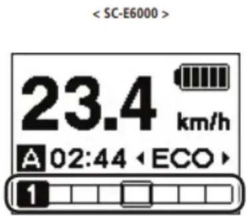
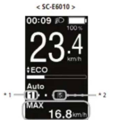
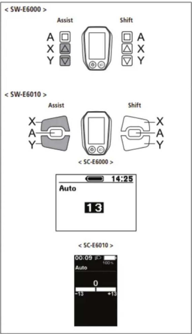
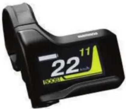
Basic screen display
Displays the status of the power assisted bicycle, traveling data.
The number of gears and the shifting mode are only displayed when using electronic gear shifting.
- Current speed
Displays the current speed. - Battery level indicator
Displays the current battery level. - Speed unit display
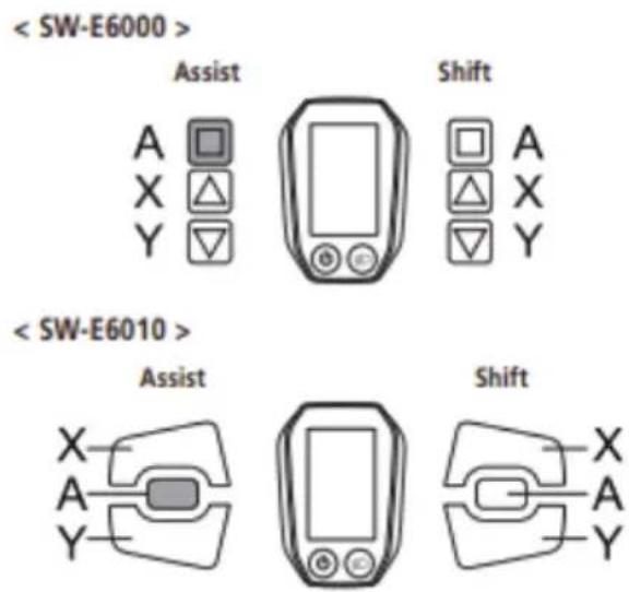
You can switch between km/h and mph. - Changing the assist mode display
Display the current assist mode. - Gear position and traveling data display Displays the current gear position or traveling data. Operate the assist switch to change the display for SC-E6000 from the gear position display to the traveling data display.
- Current time
Shows the current time. - Gear shifting mode
The current gear shifting mode is displayed as following:
SC-E6000: [A] (Auto)/[M] (Manual)
SC-E6010: [Auto]/[Manual]

This screen is an example of the SC-E6010 in the Light off road setting
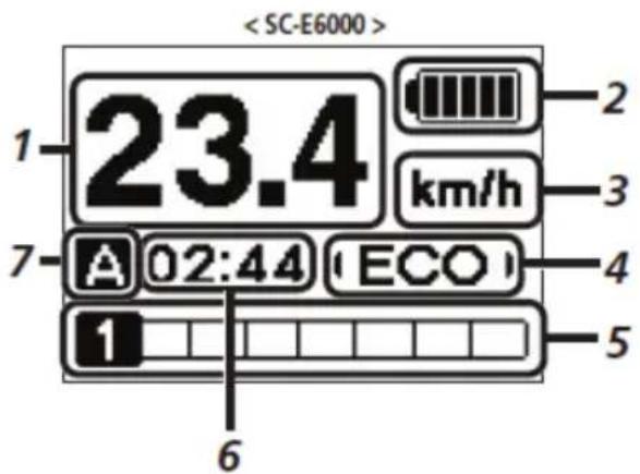
- Icon to indicate when the light is on Notifies you when the battery-powered light is on.
- Assist gauge Displays assistance level.
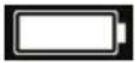
Battery level indicator
You can check the battery level on the cycle computer while riding.
| Display | Battery level |
| 81 - 100% | |
| 61 - 80% | |
| 41 - 60% | |
| 21 - 40% | |
| 1 - 20% | |
| 0% | |
| Display | Battery level |
 | 100% |
 | |
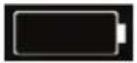 | 0% |
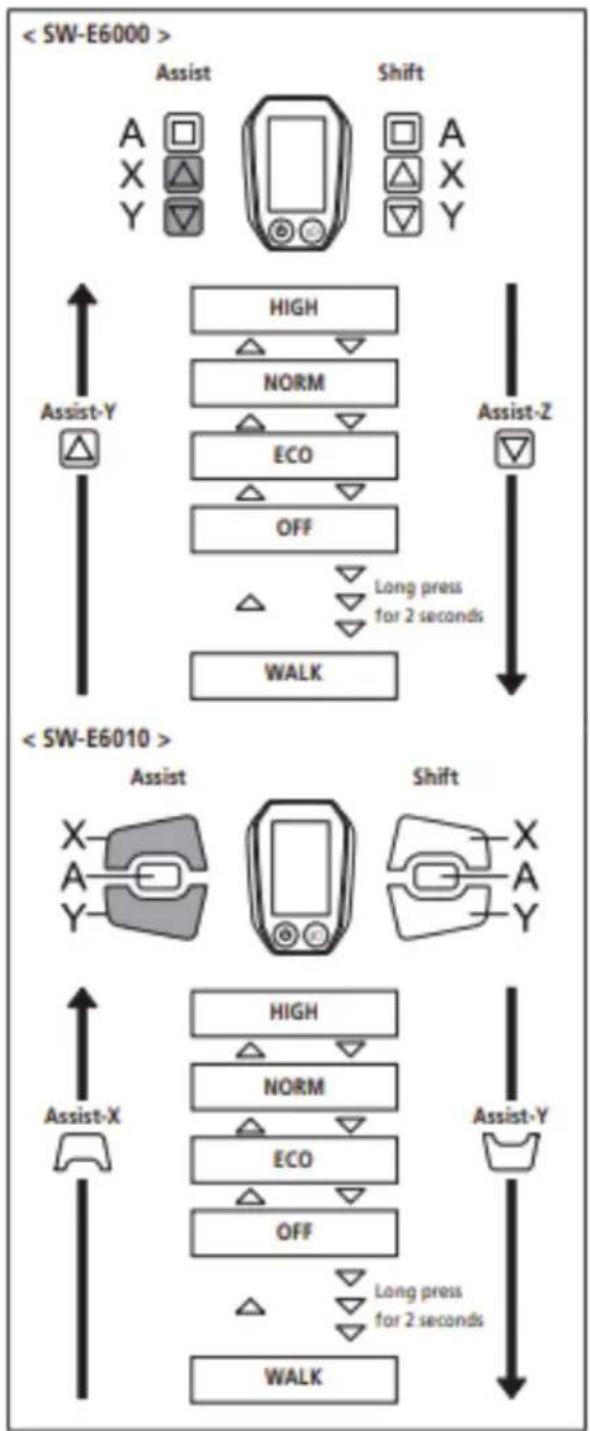
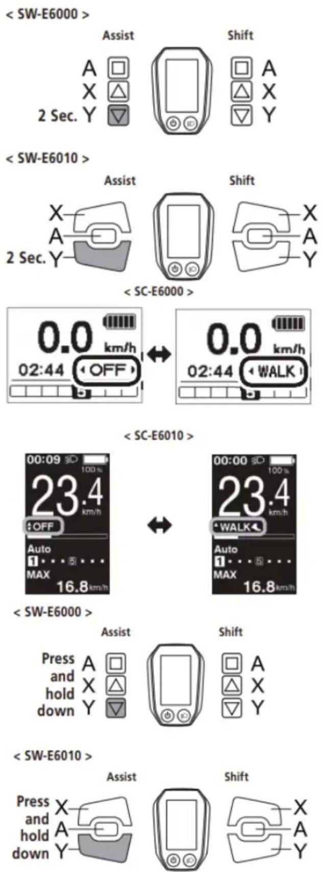
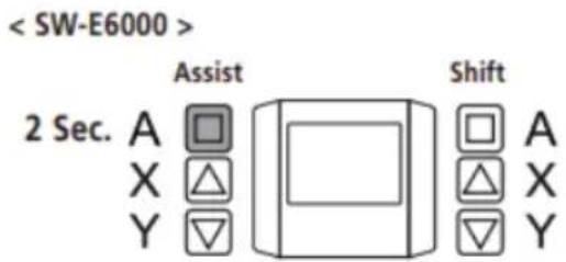
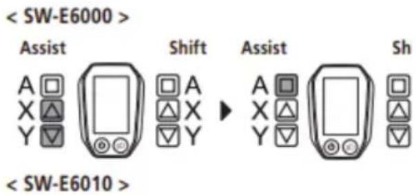
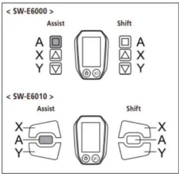
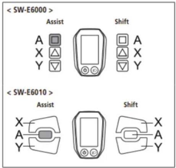
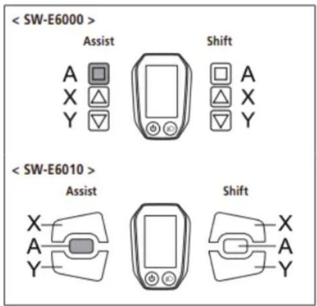
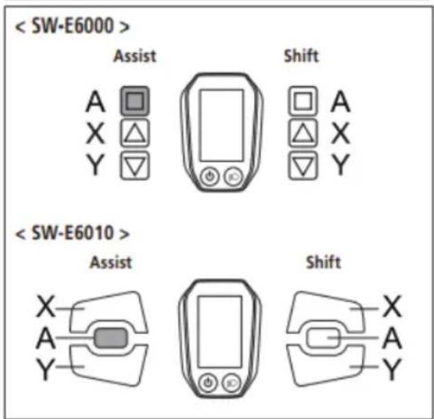
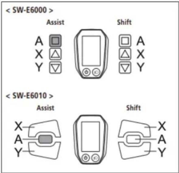
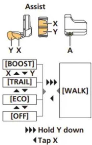
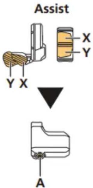
Changing the assist mode display
Display the current assist mode.
If using SW-E6000, press Assist-Y or Assist-Z on the assist switch to switch assist modes.
If using SW-E6010, press Assist-X or Assist-Y.
Display / Details
HIGH Assist high
NORM Assist normal
ECO Assist eco
OFF Assist off
WALK Walk assist
flowchart
graph TD
    A["<SW-E6000>"] --> B["Assist"]
    B --> C["Shift"]
    C --> D["High"]
    C --> E["NORM"]
    C --> F["ECO"]
    C --> G["OFF"]
    D --> H["Long press for 2 seconds"]
    E --> H
    F --> H
    G --> H
    H --> I["WALK"]
    J["<SW-E6010>"] --> K["Assist"]
    K --> L["Shift"]
    L --> M["X-A-Y"]
    N["Assist-X"] --> O["HIGH"]
    N --> P["NORM"]
    N --> Q["ECO"]
    N --> R["OFF"]
    O --> S["Long press for 2 seconds"]
    P --> S
    Q --> S
    R --> S
    S --> T["WALK"]
    U["A"] --> V["×"]
    W["X"] --> X["△"]
    Y["Y"] --> Z["▽"]
    style A fill:#f9f,stroke:#333
    style J fill:#f9f,stroke:#333
CONTROL DISPLAY
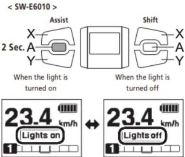
* The Walk assist mode function may not be able to be used in certain regions.
- Press Assist-Y to switch the mode to [OFF].
- Press Assist-Y once again 2 seconds until [WALK] is displayed.
- Press and hold Assist-Y to start walk assist.
When [WALK] is displayed, press and hold down Assist-Y on the assist switch to start the walk assist function.
Releasing Assist-Y stops the walk assist function, or pressing Assist-X can stop the walk assist function.
- Assist-Y is not operated for over 1 minute, the mode will change to [OFF].
- If the bicycle does not move after the walk assist function turns on, the function automatically stops. To restart the walk assist function, release the assist switch and press and hold down Assist-Y again.
- The walk assist function can operate at a maximum of 6 km/h.
• The assistance level and speed vary with the gear position
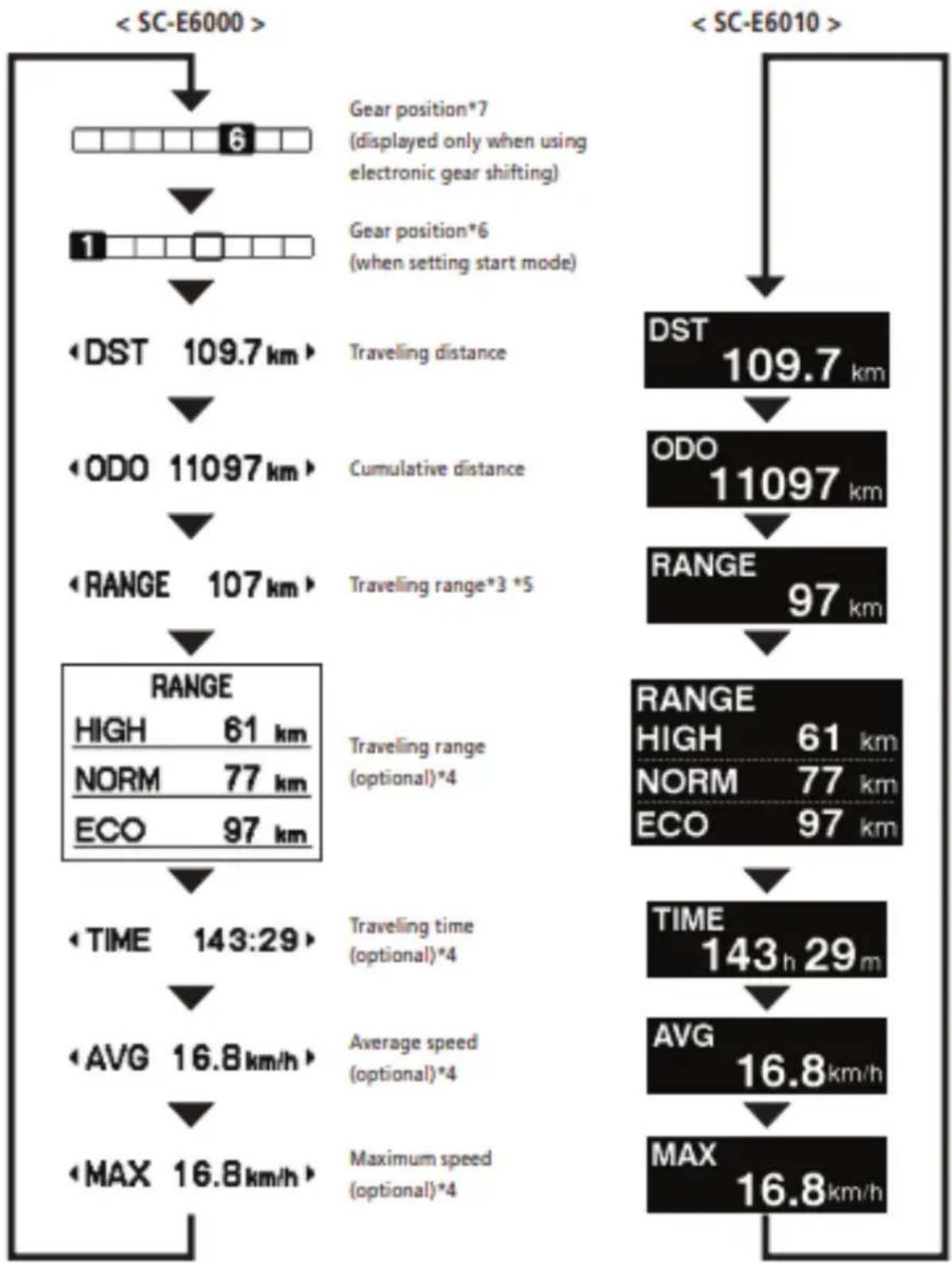
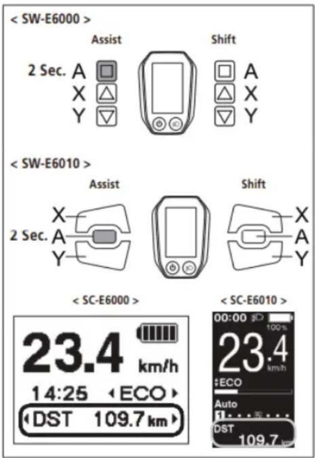
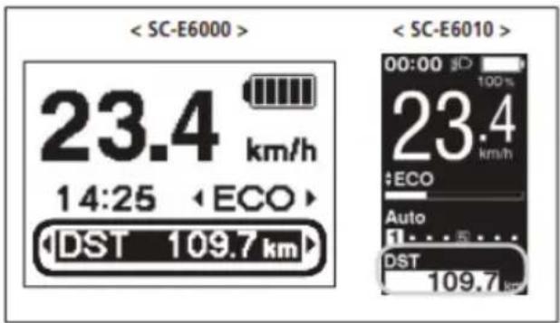
Gear position and traveling data display
Displays the current gear ratio or traveling data. The type of traveling data displayed changes each time you tap Assist-A.
*1 Gear position (displayed only when using electronic gear shifting)
*2 Gear position (when setting start mode)
*3 When [RANGE] is displayed, the battery level and the walk assist indicator do not appear on the screen.
*4 Optional item: You can configure the display settings in E-TUBE PROJECT. For details, refer to the "Connection and
communication with the PC" section.
*5 When the walk assist function is working, [RANGE ---] is displayed in the [RANGE] screen.
*6 The starting gear position is displayed when using start mode.
*7 The gear position is only displayed when using electronic gear shifting.
other
| Stage | System | Value | |-------|------------|-------------| | Start | SC-E6000 | 6 | | Start | SC-E6010 | 109.7 km | | Range | DST | 109.7 km | | Range | ODO | 11097 km | | Range | RANGE | 97 km | | Time | TIME | 143:29 | | Time | AVG | 16.8 km/h | | Time | MAX | 16.8 km/h |Turning the battery-powered light ON or OFF
< SC-E6000 >
When the battery-powered light is connected, pressing the Assist-A for 2 seconds displays this information instead of the clock and assist mode. The light turns on and off each time it is displayed. It is displayed for about 2 seconds.
When the battery-powered light is connected, push the light button on the cycle computer to turn the light on. An icon indicating that the light is on appears on the screen. Push the button again to turn the light off.
Once the light is turned off, the icon on the screen disappears.
* When the battery powered light is not connected and [Backlight] is set to [MANUAL], pressing the light button turns the cycle computer's backlight on and off.
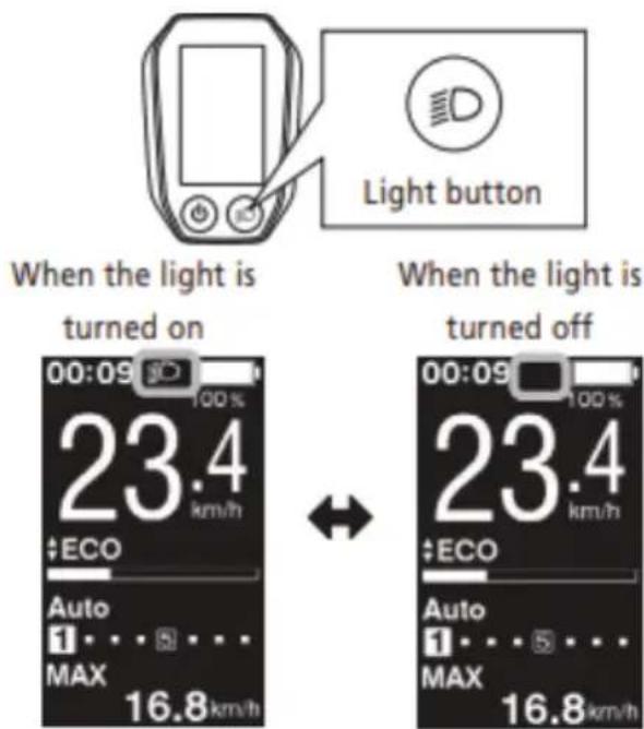
The light turns off in conjunction with the battery power. When the battery power is off, the light is off.
Switching gear shifting mode
From the basic screen, press Shift-A to switch between automatic and manual gear shifting modes.
CONTROL DISPLAY
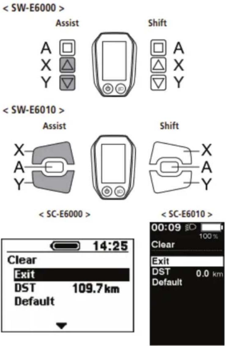
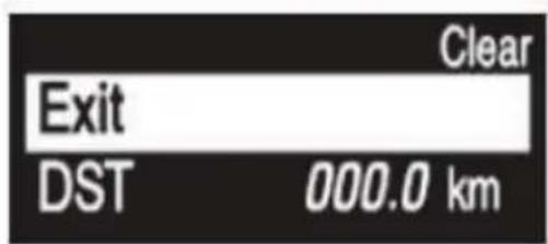
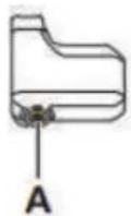
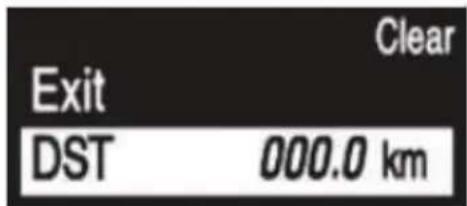
Clearing the traveling distance
You can clear the traveling distance in the main screen. If the battery-powered light is connected and configured, clear the traveling distance (DST) according to "Clear" in "About the settings menu".
When using the SC-E6000 this function can only be used when the light is not connected.
- Change the traveling data display to DST and press the Assist-A for 2 seconds.
- Release the finger when the DST indication starts blinking. In this state, pressing the Assist-A again clears the traveling distance.
- The DST indicator light stops blinking and the screen takes you back to the basic screen after leaving it alone for 5 seconds.
- When the traveling distance is cleared, TIME, AVG, and MAX are also cleared.
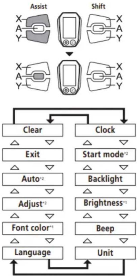
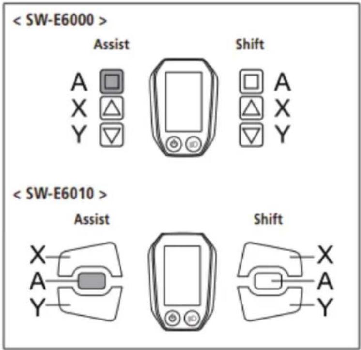
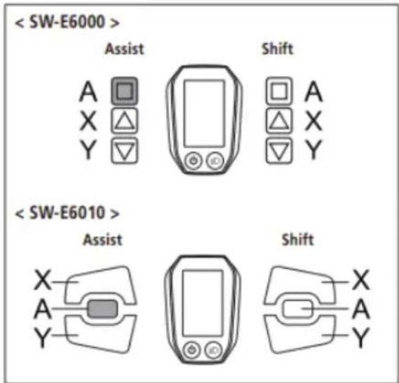
About the settings menu
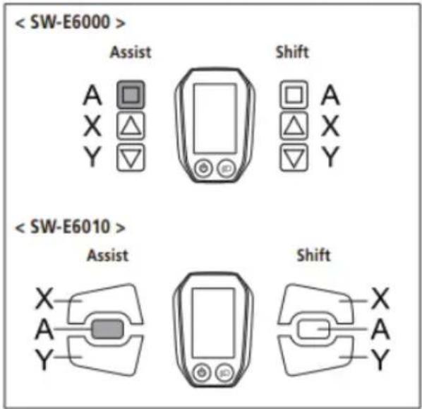
With the bicycle stopped, pressing both the Assist-X and Assist-Y at the same time for 2 seconds displays the setting screen
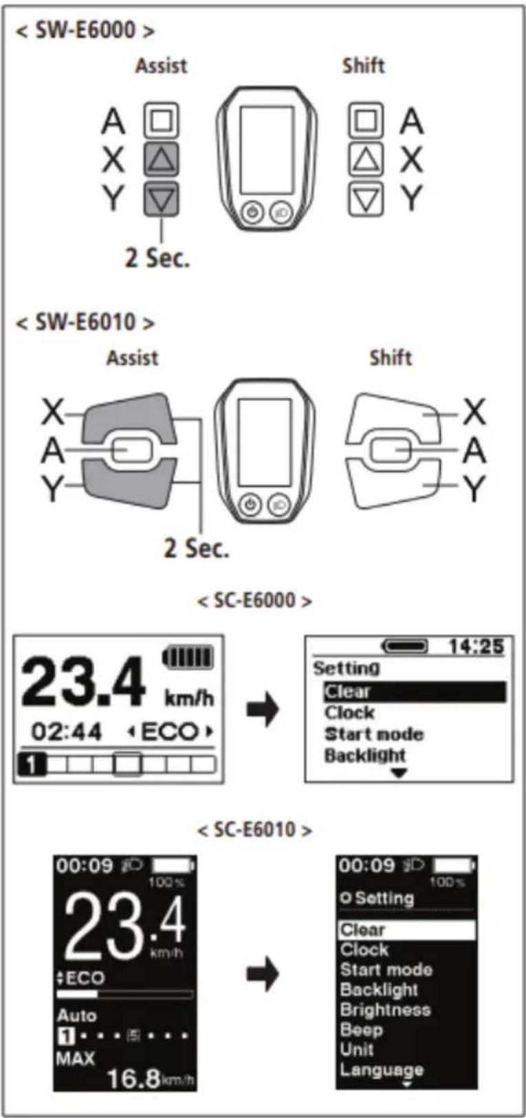
Press the Assist-X or Assist-Y to move the cursor to the item you want to configure. Pressing the Assist-A displays the setting screen for the item selected.
| Configurable items | Details |
| Clear | Clear settings |
| Clock | Clock setting |
| Start mode ^2 | Start mode setting |
| Backlight | Backlight setting |
| Brightness ^1 | Backlight brightness settings |
| Beep | Beep setting |
| Unit | Switching between km and miles |
| Language | Language setting |
| Font color ^1 | Font color settings |
| Adjust ^2 | Adjusting the electronic gear shifting unit |
| Auto ^2 | Shift timing adjustment |
| Exit | Return to the main screen |
* 1: This menu is only for the SC-E6010.
* 2: This operation is only available when using electro gear shifting.
flowchart
graph TD
    A["Assist"] --> B["Shift"]
    B --> C["Clear"]
    B --> D["Clock"]
    C --> E["Exit"]
    D --> F["Start mode*2"]
    E --> G["Auto*2"]
    F --> H["Backlight"]
    G --> I["Adjust*2"]
    H --> J["Brightness*1"]
    I --> K["Font color*1"]
    J --> L["Beep"]
    K --> M["Language"]
    L --> N["Unit"]
    M --> O["End"]
CONTROL DISPLAY
Clear the traveling distance, or reset the display setting to default.
When the traveling distance is cleared, TIME, AVG, and MAX are also cleared.
- Press the Assist-X or Assist-Y to move the cursor to the item you want to configure.
Configurable items / Details
Exit Return to the setting menu screen
DST Clearing the traveling distance
Default Reset the SC display setting to default
Default value set in the SC display setting
Configurable items / Default value
Backlight ON
Beep ON
Unit km
Language English
Brightness 3
Font color White
- Pressing the Assist-A button enables the setting item indicated by the cursor and takes you back to the "Setting menu" screen.
Configure the clock setting.
- Press the Assist-X or Assist-Y to set the hour.
Press Assist-X to increase the numbers.
Press Assist-Y to decrease the numbers.
- Pressing the Assist-A enables the set value and moves you to the minutes setting.
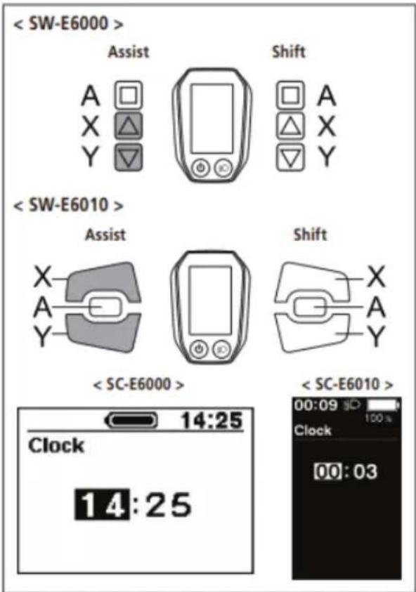
- Press the Assist-X or Assist-Y to set the minutes.
- Pressing the Assist-A enables the set value and takes you back to the "Setting menu" screen.
You can change the numbers quickly by holding down the Assist-X or Assist-Y
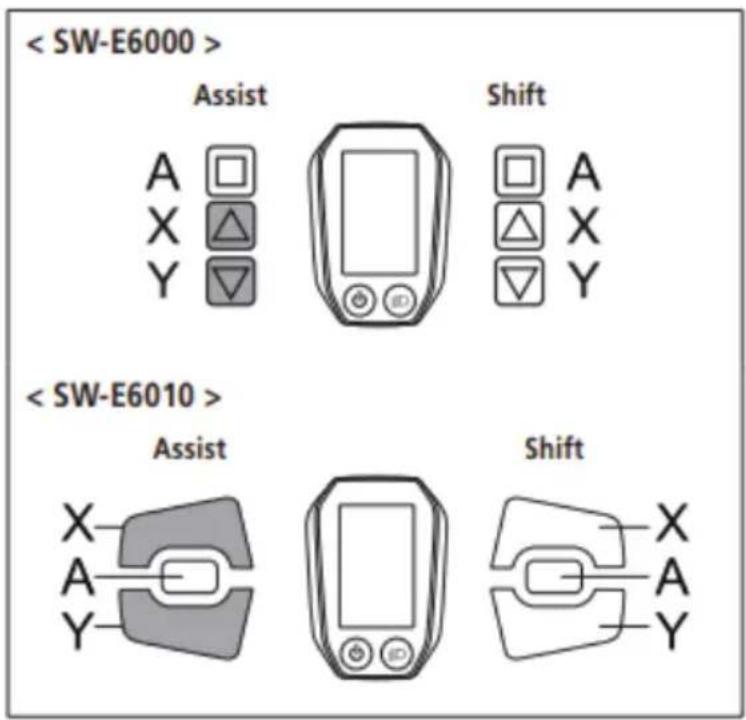
Start mode
Set the start gear when using start mode function.
- Press the Assist-X or Assist-Y to move the cursor to the item you want to configure.
Configurable items / Details
OFF No setting
2 2-speed
3 3-speed
4 4-speed
5 5-speed
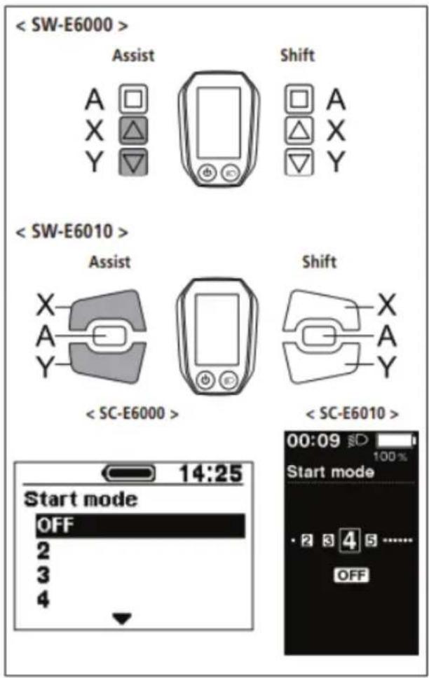
- Pressing the Assist-A button enables the set value at the cursor position and takes you back to the "Setting menu" screen.
CONTROL DISPLAY
Backlight
Configure the display backlight setting.
- Press the Assist-X or Assist-Y to move the cursor to the item you want to configure.
Configurable items / Details
ON Always turned on
OFF Always turned off
MANUAL Turns on and off in conjunction with the battery-powered light
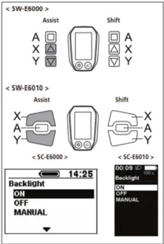
- Pressing the Assist-A button enables the setting item indicated by the cursor and takes you back to the "Setting menu" screen.
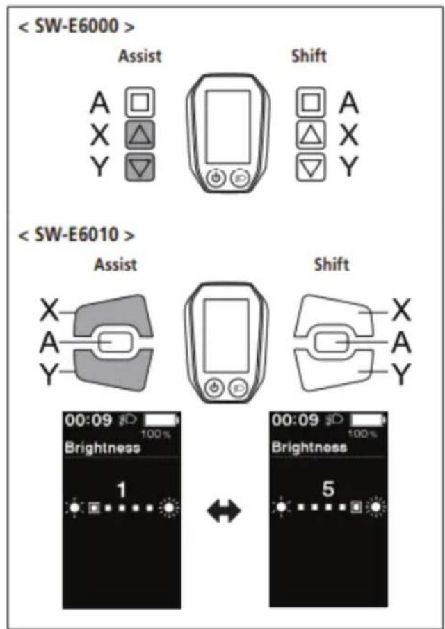
Brightness
The brightness of the backlight can be adjusted as needed.
- Press Assist-X or Assist-Y to adjust the brightness.
- Brightness can be adjusted to one of 5 levels.
- Pressing the Assist-A button enables the set value at the cursor position and takes you back to the "Setting menu" screen.
CONTROL DISPLAY
Beep
The beep sound can be turned on/off.
Press the Assist-X or Assist-Y to move the cursor to the item you want to configure.
Configurable items / Details
ON Enable beeps
OFF Disable beeps
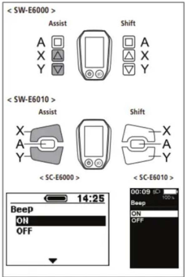
- Pressing the Assist-A button enables the setting item indicated by the cursor and takes you back to the "Setting menu" screen.
Even when [Beep] is set to [OFF], a beep will sound when there is a misoperation, system error, etc.
CONTROL DISPLAY
Unit
Distance units (km/miles) can be switched.
- Press the Assist-X or Assist-Y to move the cursor to the item you want to configure.
Configurable items / Details
Km Displayed in km
Mile Displayed in miles
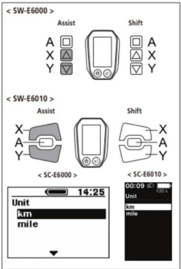
- Pressing the Assist-A button enables the setting item indicated by the cursor and takes you back to the "Setting menu" screen.
CONTROL DISPLAY
Language
Configure the language setting.
- Press the Assist-X or Assist-Y to move the cursor to the item you want to configure.
Configurable items
English
Français
Deutsch
Nederlands
Italiano
Español
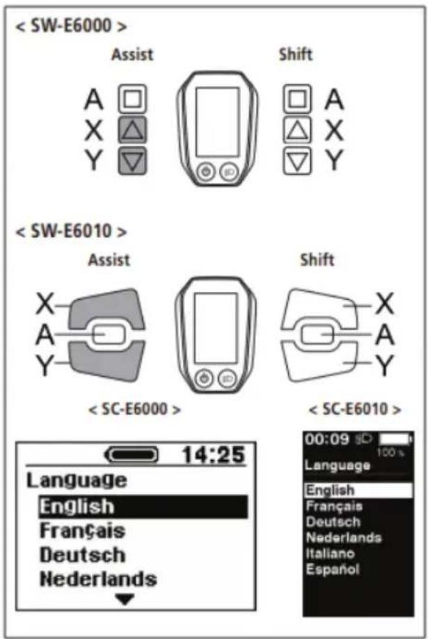
- Pressing the Assist-A button enables the setting item indicated by the cursor and takes you back to the "Setting menu" screen.
CONTROL DISPLAY
Font color
The font color can be changed.
- Press the Assist-X or Assist-Y to move the cursor to the item you want to configure.
Configurable items
White
Black
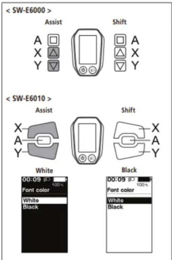
- Pressing the Assist-A button enables the setting item indicated by the cursor and takes you back to the "Setting menu" screen.
CONTROL DISPLAY
You can adjust gear shifting only when using an electronic gear shifting unit.
If you need to adjust the derailleur, contact the place of purchase.
Auto
Shift timing can be adjusted when in automatic shift mode.
-
Press Assist-X or Assist-Y to adjust the values.
-
Pressing Assist-X and adjusting the value upward adjusts shift timing to make pedaling easier.
- Pressing Assist-Y and adjusting the value downward adjusts shift timing to make pedaling harder.
CONTROL DISPLAY
- Pressing Assist-A enables the adjusted value and takes you back to the "Setting menu".
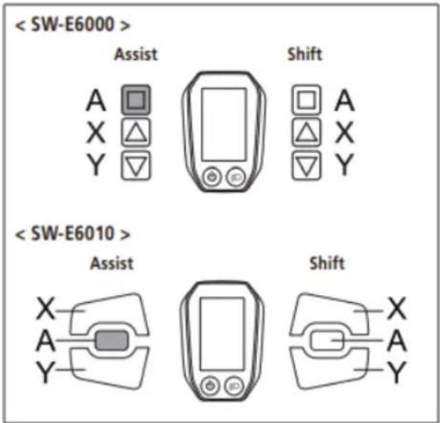
Exit
Close the setting menu and returns to the basic screen.
- Press the Assist-X or Assist-Y to move the cursor to [Exit].
- Pressing the Assist-A exits the setting menu and takes you back to the basic screen.
Battery LED lamp error indications
System errors and similar warnings are indicated by the battery LED lamps through various lighting patterns and on the cycle computer.
Warnings
This disappears if the error is fixed.
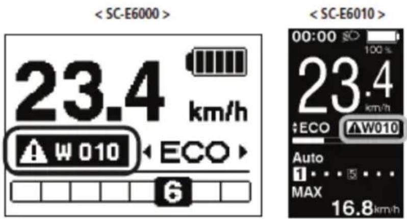
In case of any error messages displayed either by battery LEDs or on the Display, contact the shop where the product was purchased from or a bicycle shop for assistance.
CONTROL DISPLAY
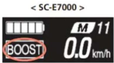
Shimano SC-E7000 Unit
Turning Power ON/OFF
The main power can be turned ON/OFF using the battery power button.
Check the following prior to turning the power ON:
- The battery is firmly attached to the battery mount
- The cycle computer is firmly attached to the bracket
Do not place your foot on the pedal when operating the power. Doing so could cause a system error.
When the main power is turned ON, all components connected to the drive unit are also turned ON (such as assist driving, cycle computer power, the electronic gear shifting mechanism, and the lights).
- The power cannot be turned ON while charging.
- If the bicycle is left unused for 10 minutes after turning the power ON, the power automatically turns OFF. (This is the automatic power OFF function.)
Press the battery power button.
The LED lights up and the battery level is displayed.
CONTROL DISPLAY
Use the same procedure to the turn the power OFF.
Do not step on the pedal when turning the power ON/OFF.
Pressing the battery power button on a BT-E8010/BT-E8020 battery for around six seconds will force the power OFF for emergencies.
When the main power is turned ON, a screen similar to that shown below is displayed, and then switches to the basic screen.

This manual uses default settings for all explanations. The functions assigned to switches when riding can be changed from those described here, by connecting to E-TUBE PROJECT.
The right switch can be replaced with a normal shifter. In this case the right switch functions explained below are no longer valid.
| Left switch(default: assist) | Right switch(default: electronic gear shifting) | ||
| Assist-X | When riding: Increase assistanceWhen setting: Move cursor or change setting | Shift-X When riding: Shifting up | |
| Assist-Y | When riding: Decrease assistanceWhen setting: Move cursor or change setting | Shift-Y | When riding: Shifting down |
| A | When riding: Switch traveling data displayed on cycle computerWhen setting: Switch cycle computer screen or confirm setting changes | ||
Be sure to keep turning the crank during gear shifting.
This displays the status of the bicycle and traveling data. The gear position is only displayed for electronic gear shifting.
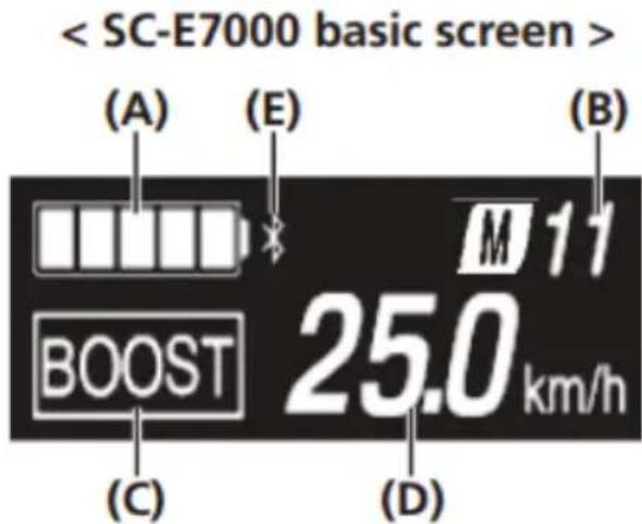
(A) Battery level indicator
(D) Current speed
(B) Gear position display
(E) Bluetooth® LE icon. Only displayed when an external device is connected over Bluetooth® LE.
(C) Current assist mode
The battery level is shown as an icon.
| Display | Battery level | |
 | 81%-100% | |
 | 61%-80% | |
 | 41%-60% | |
 | 21%-40% | |
 | 1%-20% | |
 | 0% | |
Switching the assist mode with the switch unit
If no assist switch is connected, you can also hold down A to switch to assist mode. However, it cannot be switched to [WALK] mode.
Press Assist-X or Assist-Y.
flowchart
graph TD
    A["Assist"] --> B["X"]
    A --> C["Y"]
    A --> D["A"]
    E["[BOOST"]] --> F["[TRAIL"]]
    G["[ECO"]] --> H["[OFF"]]
    I["[WALK"]] --> F
    I --> H
    F --> J["Hold Y down"]
    H --> K["Tap X"]
Switching to walk assist mode
- Stop the bicycle.
- Release your feet from the pedals.
- Hold down Assist-Y until it reaches the following state (around two seconds).
- The assist mode shown on the display switches to [WALK].
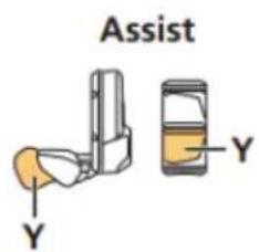
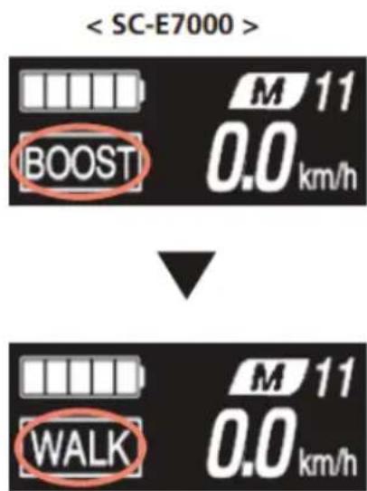
If it is impossible to switch to walk assist mode for any reason (the bicycle is not stopped, there is pressure applied to the pedals, etc.), a warning sound will be played.
If nothing is done for one minute after switching to walk assist mode, it will switch back to the assist mode that was selected before switching to walk assist mode.
CONTROL DISPLAY
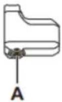
Press Assist-X to exit walk assist mode.
[WALK] mode is canceled, and the system restarts in the mode it was in prior to setting [WALK] mode.
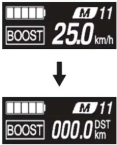
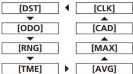
Switching Traveling Data Display
1. Press A.
The traveling data display will switch each time it is pressed.
flowchart
graph TD
    A["[DST"]] --> B["[ODO"]]
    B --> C["[RNG"]]
    C --> D["[TME"]]
    E["[CLK"]] --> F["[CAD"]]
    F --> G["[MAX"]]
    G --> H["[AVG"]]
Display item / Explanation
[DST] Traveling distance*1
[ODO] Cumulative distance
[RNG] Maximum traveling distance*2*3
[TME] Traveling time*4
[AVG] Average speed*4
[MAX] Maximum speed*4
[CAD] Crank rotation speed*4*5
[CLK] Current time*4
CONTROL DISPLAY
*1 Traveling data can be reset by holding Assist-A while displaying [DST]. The [ODO] information will not be reset.
*2 The battery level is not displayed while displaying [RNG]. The traveling range should be used as a reference only.
*3 When walk assistance is functioning, the [RNG] screen display changes to [RNG ---].
*4 This item is optional. Whether to show this or not can be set by conneng E-TUBE PROJECT. Refer to "Items Configurable in E-TUBE PROJECT" in "CONNECTION AND COMMUNICATION WITH DEVICES."
*5 Electronic gear shifting only.
The screen will switch back to displaying the speed once 60 seconds have passed after displaying the traveling data.
Pressing A with the speed information displayed will switch the displayed traveling data in sequence from [DST].
Resetting the traveling distance
Reset the traveling distance displayed on the basic screen.
When the traveling distance is reset, [TME] (traveling time), [AVG] (average speed), and [MAX] (maximum speed) will also be reset.
- Press A to switch the traveling data display to [DST].
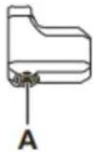
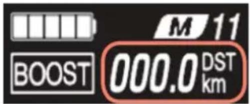
- Continue to hold A until the number displayed for [DST] flashes.
- Press A.
The traveling data is cleared.
If nothing is done for five seconds after the number for [DST] begins flashing, it will stop flashing and the screen will return to the basic screen.
CONTROL DISPLAY
Setting Menu
-
Stop the bicycle.
-
Perform the following to switch to the setting menu.
- Hold down A until the screen switches to the setting menu.

- Select a menu item.
(1) Press Assist-X or Assist-Y to move the cursor.
(2) Press A.
The display switches to the screen for the selected item.
CONTROL DISPLAY
Selectable items / Explanation
[Clear] Resets the traveling distance and display settings. [Clock] Sets the current time. [Light] Turns the light connected to the drive unit ON/OFF. [Beep] Turns the operation sound ON/OFF. [Unit] Switches the display unit between km and mile. [Language] Sets the display language. [Font color] Switches the font color between black and white. [Adjust] *1 Adjusts gear shifting for the electronic gear shifter. [Shift timing] *1 Not used. [RD protection reset] *2 Performs RD protection reset. [Exit] Returns to the basic screen.
*1 Electronic gear shifting only. *2 Electronic gear shifting rear derailleur models only
[Clear] Setting reset
Resets the traveling distance.
When the traveling distance is reset, [TME] (traveling time), [AVG] (average speed), and [MAX] (maximum speed) will also be reset.
-
Display the [Clear] menu. (1) Display the setting menu. (2) Press Assist-X or Assist-Y, select [Clear], and then press A.
-
Press Assist-X or Assist-Y to select the item to reset.
Selectable items Explanation
[Exit] Returns to the setting menu. [DST] Resets the traveling distance.
CONTROL DISPLAY
- Press A to reset the selected item.
The display will automatically return to the setting menu.
[Clock] Time setting
Sets the current time. First set the "Hour" and then the "Minute." When setting numbers in steps 2 and 4, you can hold Assist-X or Assist-Y to quickly change numbers.
- Display the [Clock] menu.
(1) Display the setting menu.
(2) Press Assist-X or Assist-Y, select [Clock], and then press A.
- Press Assist-X or Assist-Y to change the "Hour" number.
- Press Assist-X to increase the number.
- Press Assist-Y to decrease the number.
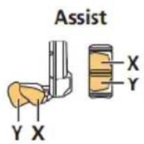
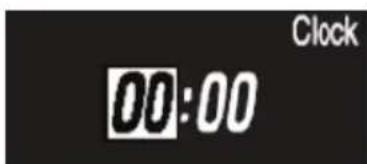
- Press A to finalize the setting. The cursor moves to the "Minute" number.
![EMG Royal - [Clock] Time setting - 3](/content/2026/04/591199/images/21e60b25e19367580f824c2a9a20c1012cb2dc4b0cae98ccc812f433d192eac0.jpg)

- Press Assist-X or Assist-Y to change the "Minute" number.
- Press Assist-X to increase the number.
- Press Assist-Y to decrease the number.
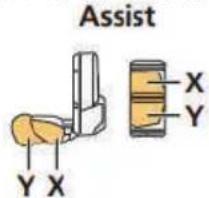
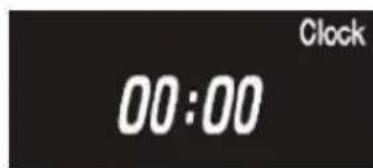
- Press A to finalize the setting. The display will automatically return to the setting menu.
CONTROL DISPLAY
[Light] Light ON/OFF
Turns the light connected to the drive unit ON/OFF.
- Display the [Light] menu.
(1) Display the setting menu.
(2) Press Assist-X or Assist-Y, select [Light], and then press A.
- Press Assist-X or Assist-Y to select the item to set.
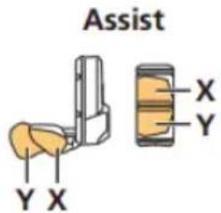
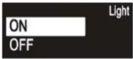
Configurable items/Explanation
[ON] Sets the light to always be ON.
[OFF] Sets the light to always be OFF.
- Press A to finalize the setting. The display will automatically return to the setting menu.
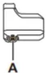
[Beep] Beep setting
Turns the operation sound ON/OFF.
Even if the operation sound is set to [OFF], a beep will sound when there is an incorrect operation, system malfunction, etc.
- Display the [Beep] menu.
(1) Display the setting menu.
(2) Press Assist-X or Assist-Y, select [Beep], and then press A.
- Press Assist-X or Assist-Y to select the item to set.
CONTROL DISPLAY
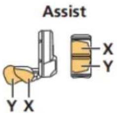
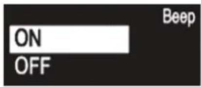
Selectable items / Explanation
[ON] Turns the operation sound ON.
[OFF] Turns the operation sound OFF
- Press A to finalize the selected setting. The display will automatically return to the setting menu.
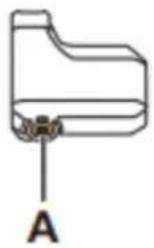
[Unit] km/mile switching
Switches the display unit between km and mile.
- Display the [Unit] menu.
(1) Display the setting menu.
(2) Press Assist-X or Assist-Y, select [Unit], and then press A.
- Press Assist-X or Assist-Y to select the item to set.
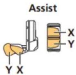
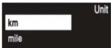
Selectable items/ Explanation
[km] Display in km.
[mile] Display in miles.
- Press A to finalize the selected setting. The display will automatically return to the setting menu.
CONTROL DISPLAY
[Language] Language setting
Sets the display language.
-
Display the [Language] menu.
(1) Display the setting menu.
(2) Press Assist-X or Assist-Y, select [Language], and then press A. -
Press Assist-X or Assist-Y to select the item to set.
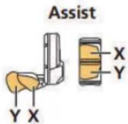

Selectable items / Explanation
[English] English
[Français] French
[Deutsch] German
[Nederlands] Dutch
[Italiano] Italian
[Espanol] Spanish
- Press A to finalize the selected setting. The display will automatically return to the setting menu.
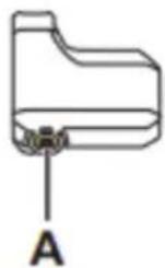
[Font color] Font color settings
Switches the font color between black and white.
- Display the [Font color] menu.
(1) Display the setting menu.
(2) Press Assist-X or Assist-Y, select [Font color], and then press A.
- Press Assist-X or Assist-Y to select the item to set.
CONTROL DISPLAY
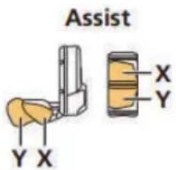
![[White] White Font color Black](/content/2026/04/591199/images/2e1383cc62c85389e961f1a40aa5e3bf63b5360cf6e03cee19f5d01cc9fabdce.jpg)
![[Black] White Font color Black](/content/2026/04/591199/images/ec60dd200905040938b7b2d9eba9b6594f47234f41590f2de3490c7bed2712c7.jpg)
Selectable items Explanation
[White] Displays white text on a black background.
[Black] Displays black text on a white background.
- Press A to finalize the selected setting. The display will automatically return to the setting menu.
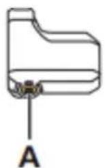
Error Indications
The battery LEDs are used to notify the user of system malfunctions, and errors on the cycle computer.
Warnings
If the situation is resolved, this indication will disappear. If the situation does not improve, consult a distributor.
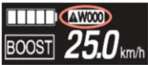
In case of any errors, consult a distributor, bicycle shop, mechanic or the dealer where the e-bike was purchased from.
DEVRON ELECTRIC CONTROL DISPLAY
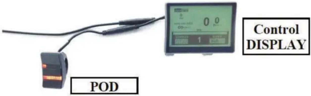
Depending on your model, the Devron Electric system comes either with POD and DISPLAY or only POD. The functions of the POD do affect what is shown on the display. Therefore the function of the display is explained first.
When the ebike is turned on, the display will indicate the following information in the main screen:
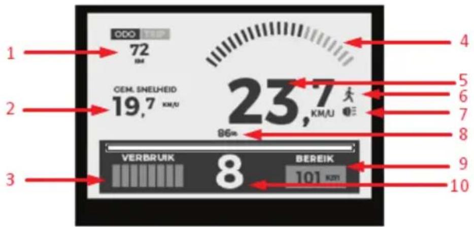
- Odometer (total) / Trip Odometer;
- Average speed of last trip;
- Battery power output bargraph;
- Motor Torque;
- Current speed of travel;
- Walk assist ON/OFF.
- Lights ON/OFF;
- Battery charge level in %;
- Range based on battery charge level and assist mode selected.
- Assist level;
CONTROL DISPLAY
DEVRON ELECTRIC CONTROL POD
The Pod can be used without Screen display. The motor assist levels, and battery levels are displayed on the pod by two distinct rows of LEDs.
Top row of LEDs indicate the level of assist. Bottom row of LEDs indicate the battery level..
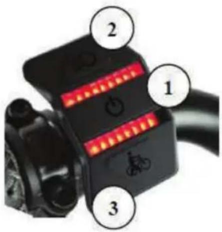
Main Button (1)
Press and hold (2-3 seconds) main button to power on/off the electric system.
Secondary Button (2)
Push the secondary button (2) to increase the assist level (level 1 level 9). Press and hold the button to toggle on/off lights function. This will also operate the screen backlight on and off if equipped.
Secondary Button (3)
Push the secondary button (3) to decrease the assist level (level 9 level 1). Press and hold the button to engage the walk assit function. Walk assist mode will cancel once you release the button.
Reset the average speed and the last distance traveled
Press Main button (1) button to select between Distance (total) or Last distance traveled. (the information displayed in area 1 of the LCD).
Select TRIP and then press Buttons 2 and 3 simultaneously until the displayed information is set to 0. The total distance traveled can not be reset.
The electric bicycle is delivered with all settings for use at optimal parameters as specified by the manufacturer and the law.
For other settings, please contact the shop where the electric bicycle was purchased from, or the nearest specialist center.
Rechargeable Battery
The battery can not be used immediately after delivery.
The battery can only be used after a complete charging cycle using the specified charger.
- Charge the battery before use.
- It is recommended to use only chargers identical to the original one with which the electric bicycle was sold. If a battery or charger from another manufacturer is used, please carefully read the instructions of the manufacturer.
When charging, use the battery and charger combination supplied and specified by the producer. Otherwise you risk overheating, explosion or battery ignition.
If the electric bicycle is stored for a longer period of time, the battery will require charging before use. After the first charge, the battery starts to gradually deteriorate due to charge/discahre cycles and use.
The ebike is equipped with a high-performance lithium ion rechargeable battery. The rechargeable battery supplies the drive system and light system with power once switched on.
The power of the rechargeable battery depends on certain factors such as age, type, usage rate, as well as maintenance. The full performance (capacity) of a new battery is reached after aprox. 2-5 complete charging cycles.
A complete charge cycle means charging till 100% without interrupting prematurely. When the drive system is on, you can check the battery charge status on the Control Display or directly on the battery (except frame integrated batteries).
Push the button (1) located near the LED level display of the battery. The charge status will be indicated by LED lights. The LEDs will switch off automatically after a brief time.
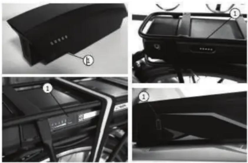
RECHARGEABLE BATTERY
Use only the specified original rechargeable battery for the ebike.
- A rechargeable battery with damaged housing must be replaced immediately. - Keep the rechargeable battery away from fire and excessive heat.
• Never put the rechargeable battery into the microwave
- Never hold the rechargeable battery under water. Never clean it with a high-pressure cleaner.
- Never expose the rechargeable battery to any strong impacts or permanent vibrations.
- Never attempt to open or repair the rechargeable battery. Replace completely if defective.
• Take out the rechargeable battery when transporting the ebike on vehicle carrier systems.
CHARGING THE BATTERY
Charge the rechargeable battery completely if possible after every long ride. This type of rechargeable battery does not suffer any memory effect. You can charge the rechargeable battery on or off the bike.
- Switch off the drive system before charging;
- Push aside the protective cap of the charging socket (2) on the rechargeable battery;
- Connect the main cable of the charger into the main socket;
- Connect the charging plug to the charging socket (2) of the rechargeable battery.
- Check the start of charching;
- Charging process stops automatically when the battery is fully charged.
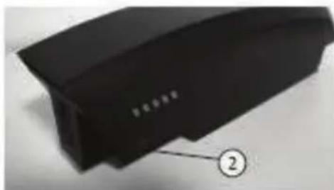
natural_image
Close-up of a black plastic electronic component with a numbered label pointing to its edge (no readable text or symbols)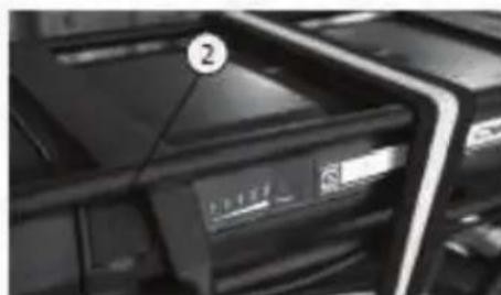
natural_image
Close-up of a black electronic device with a labeled component (number 2) and a display screen, no readable text or symbols beyond the label.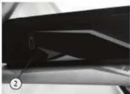
natural_image
Close-up of a dark, elongated object with a small protrusion and a numbered label (②) pointing to it, no readable text or symbols present.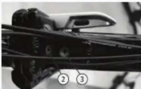
natural_image
Close-up of a mechanical component with numbered callouts (2 and 3) indicating parts of interest, no readable text or symbols present.REMOVING THE BATTERY
Rack battery
- Switch off the drive system;
- Insert the key into the rechargeable battery lock (3) and turn counterclockwise to unlock;
- Pull out the battery from the rack.
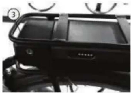
natural_image
Close-up of a black athletic vehicle chassis with visible frame and buttons (no text or symbols)Sideclick battery | Downtube battery | Frame battery
- Turn off the drive system;
- Insert the key into the battery lock and turn clockwise to unlock;
- Pull out the battery to the side with your other hand.
Frame battery (Folding EBike)
- Turn off the drive system;
- Open the frame as described in the Folding ebike section;
- Insert the key into the battery lock and turn it counterclockwise.
- Pull the battery out of the frame.
INSERT BATTERY
Luggage carrier battery
- Push the battery into the rack slot completely; To secure the battery, push the key into the lock and turn it clockwise.
Sideclick battery | Downtube battery | Frame battery
- Push the battery into the holder until the lock secures in.
Frame battery (Folding EBike)
- Fold in the frame, if not done so before removing the battery;
- Push the battery completely into the frame slots.
- Turn the key clockwise to secure the battery in;
- Remove the key.
STORING THE BATTERY
Always store the battery fully charged, as cells may be damaged or even destroyed in case of full discharge. In this case the warranty will be void!
The rechargeable battery must be stored in a dry and cool, frostfree room (7-10°C). Danger of short circuit and fire!
Lithium ion rechargeable batteries have a very low selfdischarge rate. Still, we recommend charging the battery for at least 2 hours every 3 months if not used.
RANGE
The range of your ebike may be reduced by certain factors that may include:
- Charge Level;
- Total weight (cyclist + payload)
- Pedalling rate;
- Ambient temperature;
- Tyre pressure;
- Assist level;
- Old/ residual capacity of the battery
- Terrain;
- Headwind;
- Inclination/ elevation;
You can obtain the best possible range by not using the motor assistance all the time. Use it to accelerate, for climbs or in headwind.
Choosing a lower speed level in combination with higher pedaling rate will also increase the range. Also make sure that you always have the correct tire pressure, as this may strongly influence the range.
Switch off the drive system before any repairs, maintenance and care work and remove the battery. Danger of damage and accidents!
The ebike requires regular inspection, maintenance and servicing. Only in this way you can ensure that it permanently complies with the safety and technical requirements to operate properly.
The individual parts are exposed to stress during use, crashes, accidents or improper treatment. Any kind of cracks, scratches or colour changes may indicate that the respective part may suddenly fail. This specifically applies to bent or damaged safetyrelevant parts, such as the frame, fork, handlebar, stem, saddle, seat post, rack, all brake components, lights, pedals, wheels, tyres and tubes.
Never repair such defective parts and replace them only with genuine components without delay. If no longer available, use only compatible replacement parts. A mechanic or bicycle shop can offer the best solution in such cases.
GENERAL CARE NOTES
Ensure that no care agent, grease or oil reaches the brake linings, brake disc or tires, as the brake performance will be severely reduced. Danger of accidents!
Never use any high pressure or steam cleaners, since this may cause damage (e.g. Electric parts and paint damage, rust on the bearings, etc). Clean the ebike by hand with warm water, a bicycle cleaning agent and a soft sponge.
Do not use aggressive cleaning agents, since they may damage the paint. After cleaning, apply bicycle preservation and polishing agents, especially to corrosion susceptible parts.
In order to prevent rust, clean your ebike at regular intervals and in particular after exposed to rain or snow, mud or dust.
MAINTENANCE WORK
Regular and professional maintenance can ensure optimal and safe use of your ebike.
The following inspections should be carried out in order to prevent any potential fail:
WHEELS
Rims designed for rim brakes provide a smooth parallel braking surface while rims designed for disc brakes or hub brakes sometimes lack this surface. There should be no traces of dirt on these surfaces especially grease.
If any traces of grease or dirt are noticed, clean imediately.
If during general inspection, the rim wear level indicator is no longer visible, please contact either a bicycle shop or mechanic for immediate replacement.
If you notice any nothches or scratches on the parallel surfaces of the rim consult a bicycle shop or mechanic for best repair options.
Spin the wheel freely to check the tire sidewalls and rolling surface. The tire must not show signs of uneven wear, lumps, fabric plies, missing or torn pieces.
The tire bead must also be checked for irregularities and ensure it stays firmly against the entire rim.
Check the inflation pressure with a gauge and inflate if required with a pump.
If the inflation pressure is too high release air through the valve. Check the sides of the tire for manufacturer pressure rating specification
BRAKE SYSTEM
In case of hydraulic brakes, check for any leaks by pulling the break lever and inspecting visually the complete system.
Spin freely each wheel to check the gap between the brake pads and rim sides (when using rim brakes) or between the fork legs and rim sides (when using disc brakes).
The maximum allowed deviation is 1mm. If exceeded, the wheel needs truing.
This process requires experience and special tools and is usually covered by a mechanic or bicycle shop.
In case of mechanically actuated disc brakes, the cables must be securely tightened by bolts. Outer and inner cables should not show any damage.
Inspect the surface of the rotors for any grooves, deep scratches or other forms of mechanical damage. Replace if advised by a mechanic or bicycle shop.
Lift front wheel and rotate freely to check for rotor warping. Repeat for rear wheel. When rotating freely, the rotor should not rub on the brake pads.
CHAIN
Check visually the chain links for any damages. With the bicycle in static position, rotate the chain set in reverse to check for any strange noises, clutches, or chain tendency to skip off gear, sprocket or derailed pulleys.
Clean the chain periodically and apply special chain lube. Do not use any automotive oil, vaselines or any similar products as they quickly help to cluster dust, sand, soil, etc.
There are products specifically designed for chain maintenance. Contact a mechanic or bicycle shop for details on chain care.
GEARSHIFT
Over time, due to functional mechanical components and their complexity, the transmission may suffer from poor alignment or stretching of drive cables.
If you experience suspicious noise or malfunction, contact a mechanic or bicycle shop to make the necessary adjustments.
SADDLE AND SEAT POST
Check secure attachment by grabbing the saddle from both ends and try to rotate left and right, and then to move it up and down.
If the saddle is attached correctly to the seat post, you should not be able to make it budge.
Apply grease on the seat post end to avoid ceasing into the frame.
FORK
To check proper operation, lock the front wheel by pulling the front brake lever and compress and decompress the fork for a few times by pushing down the handlebar with your body weight.
During this process the fork should not generate noise and compress and decompress easily.
If you experience suspicious noise or malfunction, contact a mechanic or bicycle shop for inspection and repairs.
HEADSET
Inspect proper operation of headset by holding the front brake on, and gently rock the bicycle back and forth; if your headset is lose you will feel a knocking through the handlebar coming from the lower headset cup.
Lift the front of your bicycle off the ground and check if wheel flops from side to side without your hands on the handlebar; if the steering is slow or does not move from side to side is means your headset is too tight.
If you suspect any malfunction of the headset, contact a mechanic or bicycle shop for inspection and repairs.
LIGHT SYSTEM
Check the light system for proper operation and fix urgently any problem. The light system is one of the most important elements for your safety in traffic and must be maintained in perfect working order.
If you identify any malfunction of the light system, contact a mechanic or bicycle shop for inspection and repairs.
BOLT-ON CONNECTIONS | QUICKCLAMPS | PARTS and ACCESSORIES
The bolts and nuts on your bicycle must be checked for tight fit at regular intervals. If these elements are tightened too far, they may break or damage the threaded parts. If not tightened enough they can become loose. Both cases risk accidents, crashes or material damages.
Depending on the bicycle model, quick clamps can secure the wheel hubs, the folding mechanisms in case of folding bicycles, or seat posts. These quick clamps ensure removal of wheels or adjustment of seat post height, quickly and without specific tools.
Check that all clips and clamps are secured properly before use.
MAINTENANCE | CARE
The stem should be positioned on the same axis as the front wheel and the handlebar must be parallel with the font hub. The stem and handlebar should never rotate free of the front wheel or up and down. To check secure attachment grab the wheel between your knees and try to rotate the handlebar left or right. If you cannot succeed, the stem and handlebar are properly secured.
Components fitted on handlebar such as brake levers, shifters or grips must not move freely or rotate by hand.
If you do not have the experience or tools required please contact a mechanic or bicycle shop for assistance.
TORQUE SPECIFICATIONS
Components Tightening torque
| Front motor nuts 50 Nm | |
| Rear hub nuts 25-30 Nm | |
| Front hub nuts 25-30 Nm | |
| Rear motor nuts 50 Nm | |
| Pedal arm (alloy) 30 Nm | |
| Pedal Arm (steel) 30-35 Nm | |
| Pedals 30-35 Nm | |
| Handlebar clamp block screw (M6) | 10-14 Nm |
| Handlebar clamp block screw (4xM5) | 6 Nm |
| Angle adjustment screw | 18-30 Nm |
| Clamp screw stem fork shaft clamp | 15 Nm |
| Handlebar bracket attachment 20 Nm | |
| Brake pads 5-7 Nm | |
| Seat post clamping ring | 8-12 Nm |
| Saddle clamp | 18-22 Nm |
Other steel bolts VA bolts A2/A4
Metric 5.6 6.8 8.8 10.9 50 70 80
The work listed in the maintenance plan include, where required, cleaning, lubrication and setting of the part or replacement of affected component by wear or damage.
Further information on the maintenance work can be found in the previous chapter.
We recommend having a mechanic or bicycle shop perform all works needed, to ensure proper operation and safety. Parts maintenance and replacement require experience and specific tools.
| Component Commissioning | 500 Km or 6 Months | 1000 Km or 12 Months | Every 1000 Km or 12 Months | |
| Tyres x ● | ● ● | |||
| Wheel / Rim | ● | ● | ● | ● |
| Spokes x | ● ● ● | |||
| Brake system | x | ● | ● | ● |
| Lighting / reflectors | x ● | ● ● | ||
| Handlebar / stem ● | ● ● ● | |||
| Steering head bearing x | ● ● ● | |||
| Saddle / seat post | ● | ● | ● | ● |
| Frame | x ● | ● ● | ||
| Fork x | ● ● ● | |||
| Gearshift | ● | ● | ● | ● |
| Chain | x | ● | ● | ● |
| Bottom bracket / Pedals | x | ● | ● | ● |
| Sprocket set | x | ● | ● | ● |
| Other parts / accessories | x | ● | ● | ● |
| Lights system | x | ● ● ● | ||
| Screw connector /quick clamp | ● | Before every ride! | ||
MAINTENANCE PLAN
Warranty may be refused in case of damage caused by noncompliance with the maintenance plan and corresponding maintenance work, improper use, structural modifications or use of components other than initially fitted or non-compliant.
The following maintenance work has been performed according to the interval of the maintenance plan and the maintenance work description::
| MAINTENANCE MAINTENANCE MAINTENANCE MAINTENANCE MAINTENANCE | ||||
| Date: | Date: | Date: | Date: | Date: |
| No. of Kilometres: | No. of Kilometres: | No. of Kilometres: | No. of Kilometres: | No. of Kilometres: |
| Stamp/ Signature | Stamp/ Signature | Stamp/ Signature | Stamp/ Signature | Stamp/ Signature |
| MAINTENANCE MAINTENANCE MAINTENANCE MAINTENANCE MAINTENANCE | ||||
| Date: | Date: | Date: | Date: | Date: |
| No. of Kilometres: | No. of Kilometres: | No. of Kilometres: | No. of Kilometres: | No. of Kilometres: |
| Stamp/ Signature | Stamp/ Signature | Stamp/ Signature | Stack/ Signature | Stamp/ Signature |
DISPOSING OF THE EBIKE (WITHOUT RECHARGEABLE BATTERY)
natural_image
Simple line drawing of a trash bin with crossed lines indicating no waste or discharge (no text or symbols)The ebike is not considered domestic waste at the end of its service life. Instead, it must be delivered to dropoff points for recycling of electrical and electronic devices.
The rechargeable battery must be removed and disposed of separately.
The materials are reusable according to their marking. Reuse, recycling or other forms of use of old devices is an important contribution to the protection of the environment.
Ask your city administration about the disposal requirements relevant for you.
DISPOSING OF THE RECHARGEABLE BATTERY
natural_image
Simple line drawing of a trash bin with crossed lines indicating no waste or restriction (no text or symbols)Rechargeable batteries must be disposed off according to the law. As consumer you are obligated to return used and used rechargeable batteries.
Ask your city administration about the disposal requirements relevant for you
PACKAGE RECYCLING

natural_image
Recycling symbol composed of three chasing arrows forming a triangle (no text or labels)The packaging material can be partially reused. Dispose of the packaging environmentally compatible and deliver it to recycling points. Dispose of it at a public collection point.
Ask your town/municipal administration about the disposal office relevant for you.
DÈCLARATION DE CONFORMITÈ UE EU - KONFORMITÄTSERKLÄRUNG
| SOCIAL REASON / FORMA: | TREVI S.P.A. | |
| ADRESSE / DIE ANSCHRIFT: | STRADA CONSOLARE RIMINI – SAN MARINO, 62 | |
| CODE POSTAL ET VILLE / POSTLEITZAHL UND STADT: | 47924 | RIMINI (RN) - ITALY |
| TELEPHONE / TELEFON: | +39 0541.756420 | |
| INFO@TREVI.IT | ||
| CONTACTER LES PERSONNESKONTAKTPERSONEN | AGUTI EGIDIO – STRADA CONSOLARE RIMINI – SAN MARINO, 62 47924 RIMINI (RN) ITALY | |
DÉCLARER QUE LE DOC EST ÉMIS SOUS NOTRE SEULE RESPOSABILITE / ERCLÄREN DASS DASS DOKUMENT IN UNSERER ALLEINGEN VERANTWORTUNG AUSGESTELLT WIRD:
| MODELE / MODELL: | UB 28LAi / 28427 |
| TYPE DE PRODUIT / PRODUKTART: | VÈLO ÉLECTRIQUE / ELEKTRISCHES FAHRRAD |
| LOT DE PRODUCTION / PRODUKTIONSLOS | 04/22 |
natural_image
Black-and-white photo of a modern electric bicycle with front wheel and rear seat (no visible text or symbols)LE PRODUCT ESTE CONFORME A TOUTES LES DISPOSITIONES PERTINENTES DES DIRECTIVES SUIVANTES / DAS PRODUKT ERFULLET ALLE RELEVATEN BESTIMMUNGEN DER FOLGENDEN RICHTLINIEN:
DIRECTIVE 2006/42/EC / RICHTLINIE 2006/42/EC DIRECTIVE 2015/863/EU / RICHTLINIE 2015/863/EU DIRECTIVE 2014/30/EU / RICHTLINIE 2014/30/EU DIRECTIVE 2014/35/EU / RICHTLINIE 2014/3/EU
LES NORMES HARMONISÉES ET LES SPÉCIFICATIONS TECHNIQUES SUIVANTES ONT ÉTÈ APPLIQUEÈES / FOLGENDE HARMONISIERTE NORMAN UND TECHNISCHE SPEZIFIKATIONEN WURDEN ANGEWENDET:
| EN62471 | 2008 |
| EN15194 | 2017 |
| EN ISO 4210-1 LA 9 | 2014/2015 |
RIMINI, 18.11.2021
(LIEU ET DATE DE DÉLIVRANCE / ORD UND I DER ASSTELLUNG)

DÈCLARATTION DE CONFORMITÈ UE EU - KONFORMITÄTSERKLÄRUNG
| SOCIAL REASON / FORMA: | TREVI S.P.A. | |
| ADRESSE / DIE ANSCHRIFT: | STRADA CONSOLARE RIMINI – SAN MARINO, 62 | |
| CODE POSTAL ET VILLE / POSTLEITZAHL UND STADT: | 47924 | RIMINI (RN) - ITALY |
| TELEPHONE / TELEFON: | +39 0541.756420 | |
| INFO@TREVI.IT | ||
| CONTACTER LES PERSONNESKONTAKTPERSONEN | AGUTI EGIDIO – STRADA CONSOLARE RIMINI – SAN MARINO, 62 47924 RIMINI (RN) ITALY | |
DÉCLARER QUE LE DOC EST ÉMIS SOUS NOTRE SEULE RESPOSABILITE / ERCLÄREN DASS DASS DOKUMENT IN UNSERER ALLEINGEN VERANTWORTUNG AUSGESTELLT WIRD:
| MODELE / MODELL: | UB 28RA / 28414 |
| TYPE DE PRODUIT / PRODUKTART: | VÈLO ÉLECTRIQUE / ELEKTRISCHES FAHRRAD |
| LOT DE PRODUCTION / PRODUKTIONSLOS | 04/22 |
natural_image
Exterior view of a modern bicycle with a pink body and black roof (no visible text or symbols)LE PRODUCT ESTE CONFORME A TOUTES LES DISPOSITIONES PERTINENTES DES DIRECTIVES SUIVANTES / DAS PRODUKT ERFULLET ALLE RELEVATEN BESTIMMUNGEN DER FOLGENDEN RICHTLINIEN:
DIRECTIVE 2006/42/EC / RICHTLINIE 2006/42/EC DIRECTIVE 2015/863/EU / RICHTLINIE 2015/863/EU DIRECTIVE 2014/30/EU / RICHTLINIE 2014/30/EU DIRECTIVE 2014/35/EU / RICHTLINIE 2014/3/EU
LES NORMES HARMONISÉES ET LES SPÉCIFICATIONS TECHNIQUES SUIVANTES ONT ÉTÈ APPLIQUEÈES / FOLGENDE HARMONISIERTE NORMAN UND TECHNISCHE SPEZIFIKATIONEN WURDEN ANGEWENDET:
| EN62471 | 2008 |
| EN15194 | 2017 |
| EN ISO 4210-1 LA 9 | 2014/2015 |
RIMINI, 18.11.2021
(LIEU ET DATE DE DÉLIVRANCE / ORD UND | DER ASSTELLUNG)

natural_image
Black rectangular electronic device with a red lens, shown against a white background (no text or symbols visible)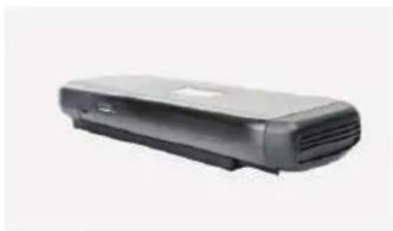
natural_image
Exterior view of a black rectangular electronic device with ventilation slots (no visible text or symbols)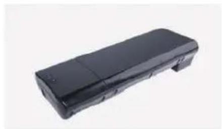
natural_image
Black rectangular electronic device with a flat top and side slots, isolated on white background (no text or symbols visible)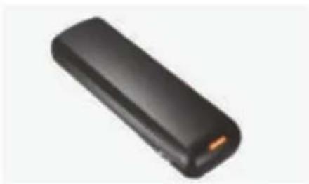
natural_image
Black rectangular electronic device with a small orange tip, shown against a white background (no text or symbols visible)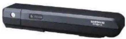
natural_image
Black handheld electronic device with 'Santawski 57-82' branding and a small circular icon on the left (no readable text beyond branding)Modell: DEVRON ELECTRIC
Spannung: 36V
natural_image
Black office phone receiver with a flat case (no visible text or symbols)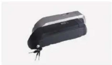
natural_image
Black and white electronic device with a small metallic connector (no visible text or symbols)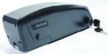
natural_image
Exterior view of a black electronic device with ports and connectors (no visible text or symbols)natural_image
Blue rectangular battery with red and black wires, no visible text or symbolsModell: Shimano BT E-6000 DT
Spannung: 36V
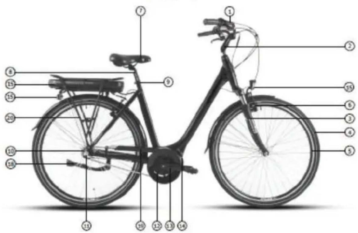
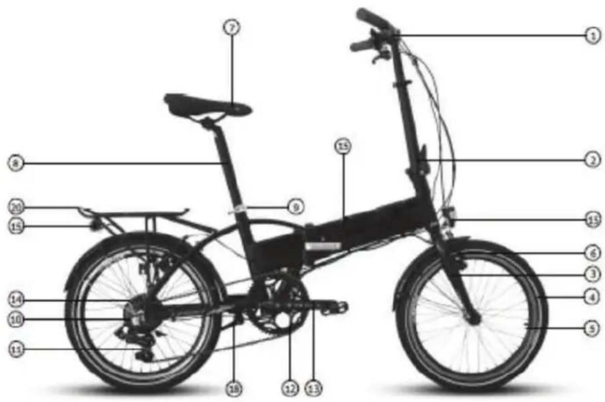
natural_image
Close-up of a hand using a clamping tool to adjust a mechanical component (no text or symbols visible)Pic.1
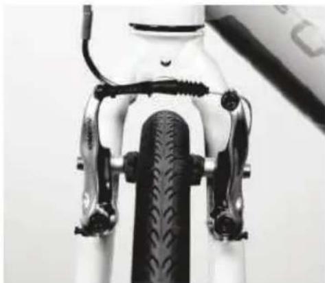
natural_image
Close-up of a bicycle front wheel and side brackets (no text or symbols visible)Pic.2
natural_image
Close-up of a bicycle's front wheel and suspension bracket (no visible text or symbols)Pic.3
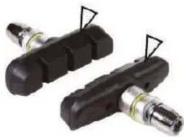
natural_image
Two black mechanical components with attached metallic fittings, no visible text or symbolsPic.4
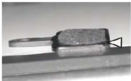
natural_image
Close-up of a metallic tool or component with a curved handle and textured surface, mounted on a flat surface (no visible text or symbols)Pic.5
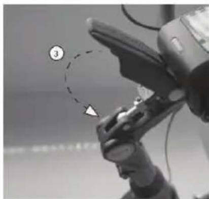
natural_image
Close-up of a robotic hand with a numbered callout highlighting a specific point (no text or symbols present)natural_image
Close-up of a person wearing a black helmet and holding a medical device (no visible text or symbols)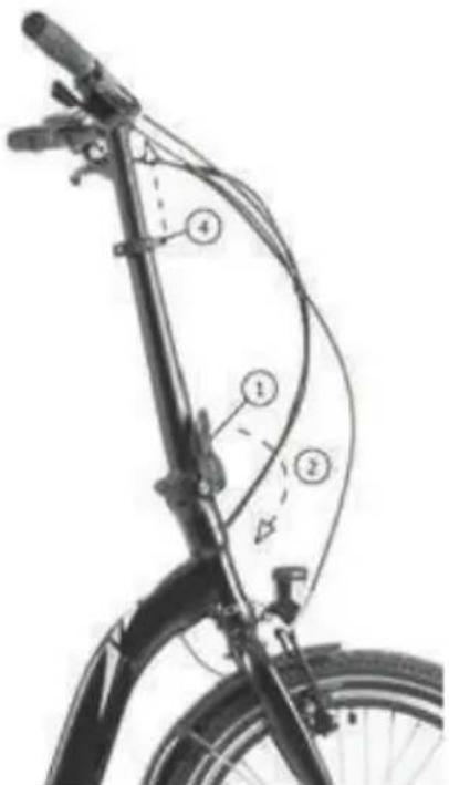
natural_image
Line drawing of a person riding a bicycle, no text or symbols presentPic. 1
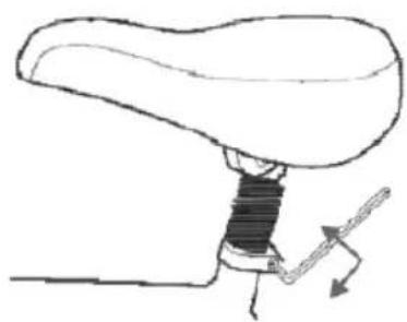
natural_image
Diagram of a mechanical lever mechanism with no text or symbolsPic. 2
natural_image
Diagram of a liver with directional arrows indicating movement or force (no text or labels)Pic. 3
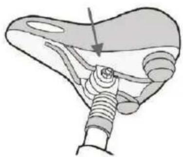
natural_image
Anatomical illustration of a mechanical joint or implant structure (no text or labels)Pic. 4
PEDALEN
natural_image
Close-up of a mechanical component with a circular arrow labeled 'CLOCKWISE' indicating clockwise rotation (no other text or symbols)LEUCHTSYSTEM
natural_image
Close-up of a bicycle wheel rim with visible tire and spokes (no text or symbols)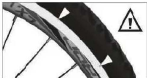
natural_image
Close-up of a bicycle tire with warning symbol (no text or labels)Pic.2
Reifen
natural_image
Two black mechanical components with arrows indicating assembly or adjustment, mounted on a tiled floor (no text or symbols visible)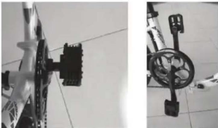
natural_image
Two black-and-white photos showing bicycle wheel components mounted on a tiled floor, no visible text or symbols.natural_image
Three-panel black-and-white photo showing a bicycle's wheel assembly with arrows indicating motion or movement (no text or symbols)natural_image
Mechanical assembly diagram showing a lever mechanism with dashed alignment lines and an arrow indicating motion (no text or symbols present)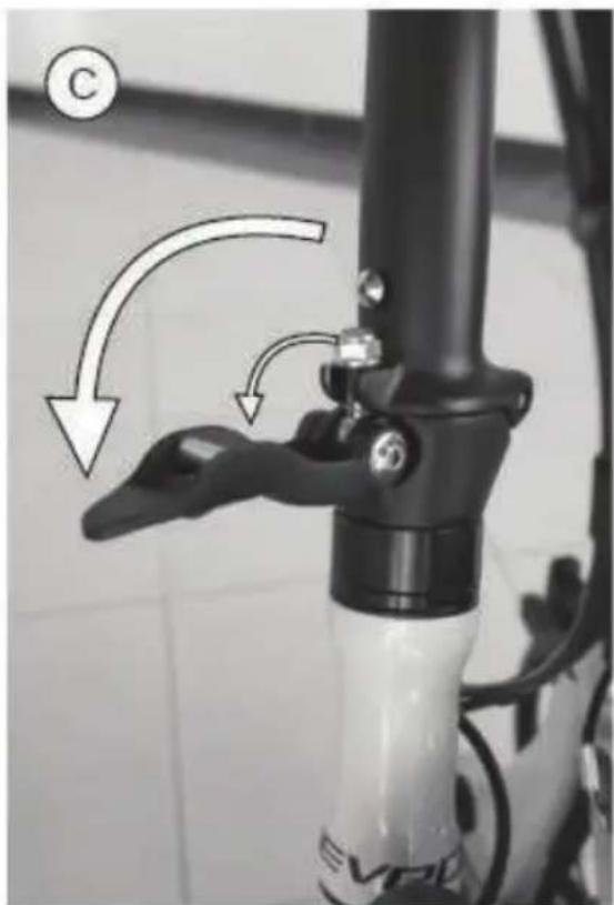
natural_image
Close-up of a bicycle lever handle and lever arm mechanism (no text or symbols visible)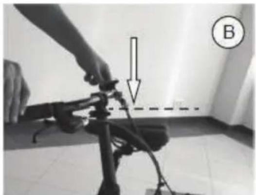
natural_image
Person adjusting a camera frame with a downward arrow and dashed line, labeled B (no text or symbols on the device itself)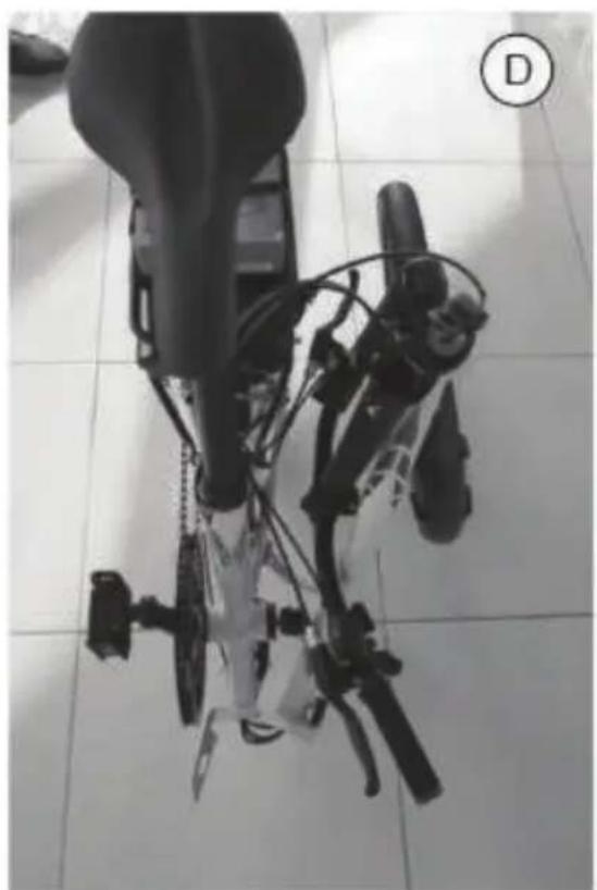
natural_image
Top-down view of a robotic device with articulated limbs and control arms, placed on tiled floor (no visible text or symbols)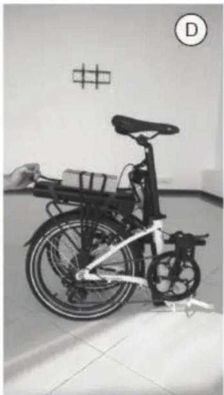
natural_image
Black-and-white photo of a bicycle with a hand holding a basket, displayed indoors near a wall with a grid pattern and letter D (no visible text or symbols on the bike itself)natural_image
Close-up of a black electronic device control panel with buttons and display (no readable text or symbols)2. Funktionen
2.1 Taste Start/Stop
2. Funktionen
2.1 Taste Start/Stop
KONTROLLEINHEITEN
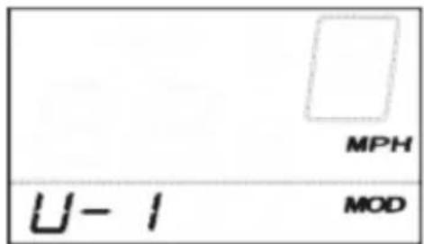

KONTROLLEIBHEITEN
KONTROLLEIBHEITEN
Taste (1)
natural_image
Close-up of a black electronic device casing with a numbered label pointing to its side (no readable text or symbols)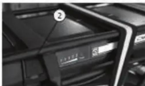
natural_image
Close-up of a printer rack with a labeled paper icon (no readable text or symbols)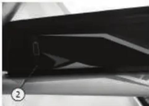
natural_image
Close-up of a glossy black object with a numbered label (2) pointing to it, no visible text or symbols.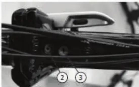
natural_image
Close-up of a mechanical component with numbered callouts (2 and 3) pointing to features, no readable text or symbols present.ENTFERNEN DES AKKUMULATORS
natural_image
Close-up of a black industrial machine component with visible control panel and wheels (no text or symbols)natural_image
Black-and-white photo of a modern bicycle with front wheel and side seat (no visible text or symbols)LE PRODUCT ESTE CONFORME A TOUTES LES DISPOSITIONES PERTINENTES DES DIRECTIVES SUIVANTES / DAS PRODUKT ERFULLET ALLE RELEVATEN BESTIMMUNGEN DER FOLGENDEN RICHTLINIEN:
DIRECTIVE 2006/42/EC / RICHTLINIE 2006/42/EC
DIRECTIVE 2015/863/EU / RICHTLINIE 2015/863/EU
DIRECTIVE 2014/30/EU / RICHTLINIE 2014/30/EU
DIRECTIVE 2014/35/EU / RICHTLINIE 2014/3/EU
LES NORMES HARMONISÉES ET LES SPÉCIFICATIONS TECHNIQUES SUIVANTES ONT ÉTÈ APPLIQUEÈES / FOLGENDE HARMONISIERTE NORMAN UND TECHNISCHE SPEZIFIKATIONEN WURDEN ANGEWENDET:
EN62471 2008 EN15194 2017 EN ISO 4210-1 LA 9 2014/2015
RIMINI, 18.11.2021
natural_image
Exterior view of a modern bicycle with a pink body and black seat (no visible text or symbols)LE PRODUCT ESTE CONFORME A TOUTES LES DISPOSITIONES PERTINENTES DES DIRECTIVES SUIVANTES / DAS PRODUKT ERFULLET ALLE RELEVATEN BESTIMMUNGEN DER FOLGENDEN RICHTLINIEN:
DIRECTIVE 2006/42/EC / RICHTLINIE 2006/42/EC DIRECTIVE 2015/863/EU / RICHTLINIE 2015/863/EU DIRECTIVE 2014/30/EU / RICHTLINIE 2014/30/EU DIRECTIVE 2014/35/EU / RICHTLINIE 2014/3/EU
LES NORMES HARMONISÉES ET LES SPÈCIFICATIONS TECHNIQUES SUIVANTES ONT ÊTÈ APPLIQUEÈES / FOLGENDE HARMONISIERTE NORMAN UND TECHNISCHE SPEZIFIKATIONEN WURDEN ANGEWENDET:
| EN62471 | 2008 |
| EN15194 | 2017 |
| EN ISO 4210-1 LA 9 | 2014/2015 |
RIMINI, 18.11.2021
natural_image
Black handheld electronic device with a red lens, shown against a white background (no text or symbols visible)
natural_image
Exterior view of a modern office building (no signage)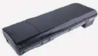
natural_image
Black rectangular electronic device with a flat top and side panel (no visible text or symbols)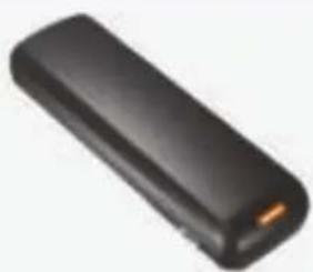
natural_image
Black rectangular electronic device with a small orange tip, isolated on white background (no text or symbols visible)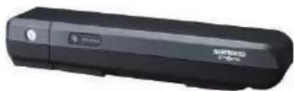
natural_image
Black USB flash drive with brand logo and model number 57-89 (no visible text or symbols beyond branding)Capacité: 8.8Ah/11Ah/14.5Ah
BMS: Standard/Smart
Dimensions Lxlxh
(sans support): 368mmX148mmX62mm
Cycles de environ. 1000@100%
chargement:
Poids: <3.2kg
Modèle: WALLE-S
Voltage: 36V
Capacité: 16Ah/13Ah/14Ah
BMS: Standard/Smart
Dimensions Lxlxh
(sans support): 375mmX150mmX64.5mm
natural_image
Black office phone receiver with a flat case (no visible text or symbols)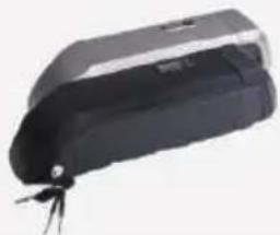
natural_image
Black and white electronic device with a small metallic clip attached (no visible text or symbols)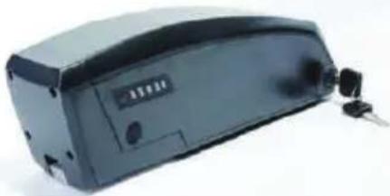
natural_image
Exterior view of a black electronic device with ports and buttons (no visible text or symbols)natural_image
Blue rectangular battery with red and black wires, connected to a small electronic component (no visible text or symbols)(sans support): 296.5mmX85mmX94mm
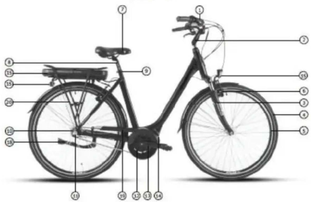
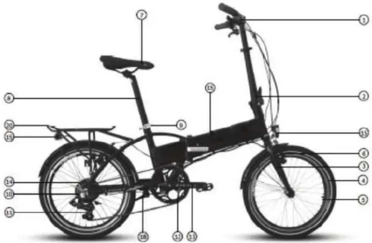
natural_image
Close-up of a hand holding a mechanical clamp or lever, with no visible text or symbolsPic.1
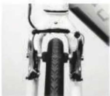
natural_image
Close-up of a mechanical component with visible gears and shafts (no text or symbols)Pic.2
natural_image
Close-up of a bicycle's wheel and suspension system (no visible text or symbols)Pic.3
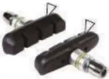
natural_image
Two black mechanical components with attached metal fittings and triangular connectors (no visible text or symbols)Pic.4
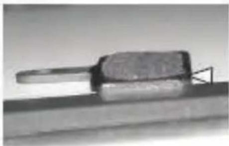
natural_image
Close-up of a metallic tool or component with a handle and base, resting on a flat surface (no visible text or symbols)Pic.5
natural_image
Close-up of a mechanical pipe fitting with numbered mounting points (no visible text or symbols)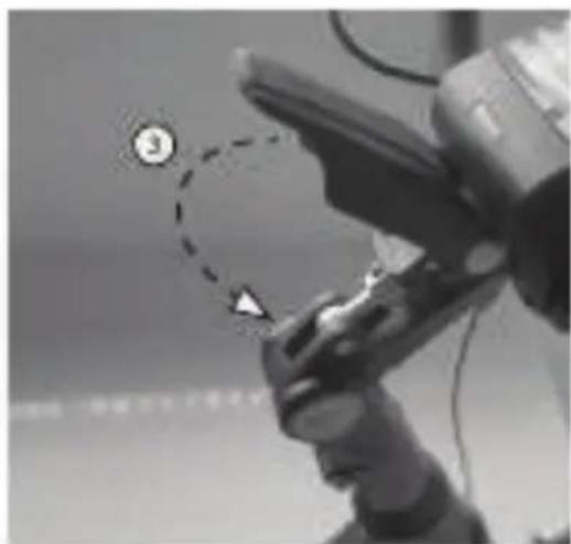
Guidon et support guidon pliable
natural_image
Black-and-white photo of a person holding a helmet with a circular badge labeled '③' (no visible text or symbols on the helmet or background)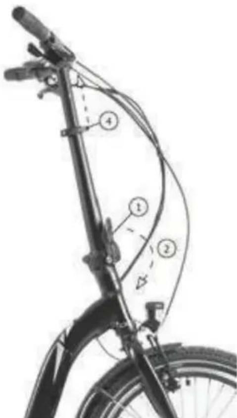
natural_image
Line drawing of a person riding a bicycle (no text or symbols)Pic. 1
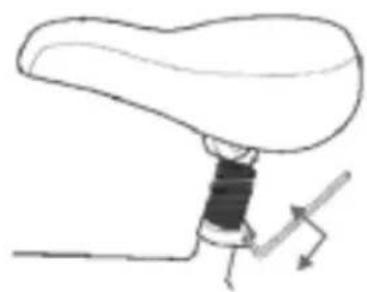
natural_image
Simple line drawing of a mechanical component with a shaft and lever (no text or symbols)Pic. 2
natural_image
Diagram of a human hand holding a liver with directional arrows indicating movement (no text or labels)Pic. 3

natural_image
Anatomical illustration of a liver with a visible vascular structure and an arrow indicating a specific area (no text or labels present)Pic. 4
PEDALES
natural_image
Close-up of a mechanical component with a circular arrow labeled 'DLOCKWISE' indicating clockwise motion (no other text or symbols)SYSTEME DE LUMIÈRES
natural_image
Close-up of a bicycle wheel rim with triangular markings (no text or symbols visible)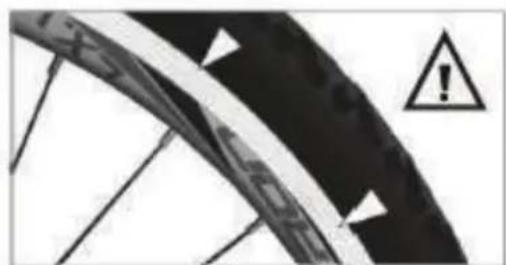
natural_image
Close-up of a bicycle wheel with warning symbol (no text or labels)Pic.2
Enveloppes
natural_image
Close-up of a black mechanical component mounted on a vertical pole against a tiled wall (no visible text or symbols)
natural_image
Close-up of a hand holding a small electronic device with two white arrows pointing to it, against a tiled floor (no visible text or symbols)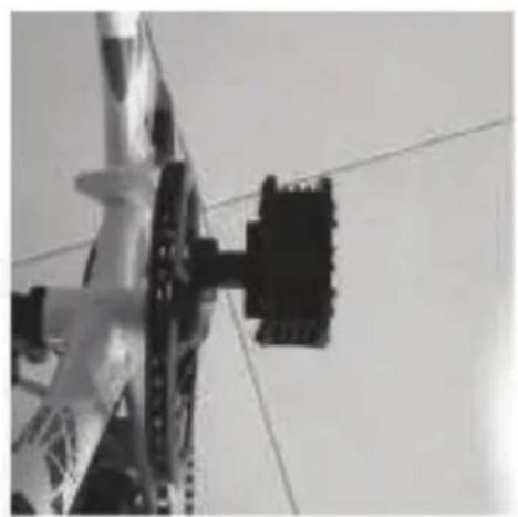
natural_image
Close-up of a mechanical component with a black bracket and chain links against a plain background (no visible text or symbols)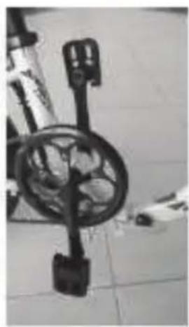
natural_image
Close-up of a mechanical device with a circular dial and handle, mounted on a tiled floor (no visible text or symbols)natural_image
Close-up of a bicycle's wheel and seat assembly (no visible text or symbols)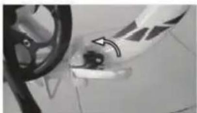
natural_image
Close-up of a car wheel and door handle with a black arrow pointing to the wheel (no visible text or symbols)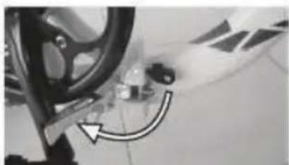
natural_image
Close-up of a car wheel and gear assembly with a curved arrow indicating motion (no visible text or symbols)natural_image
Mechanical assembly diagram showing a lever mechanism with dashed alignment lines and an arrow indicating motion (no text or symbols present)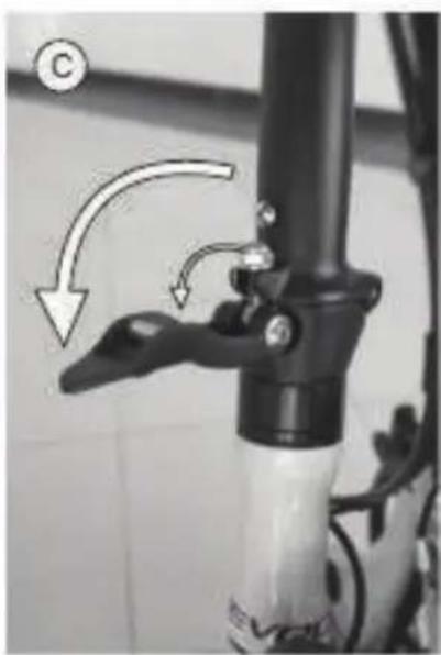
natural_image
Close-up of a bicycle lever mechanism with arrows indicating motion (no text or symbols)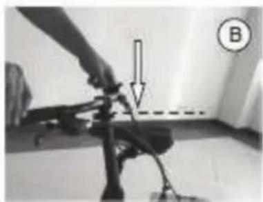
natural_image
Close-up of a person using a handheld device with a directional arrow and label B (no readable text or symbols)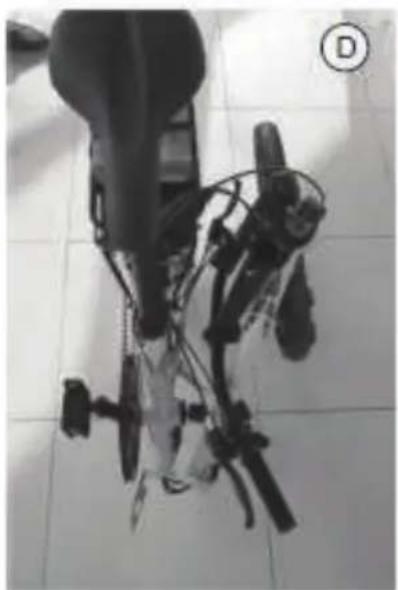
natural_image
Close-up of a mechanical device with attached wires and components, placed on tiled floor (no visible text or symbols)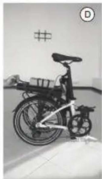
natural_image
Black-and-white photo of a bicycle with visible frame and seat, parked indoors near a wall with symbols (no readable text or labels)Unité type DP E06 LED
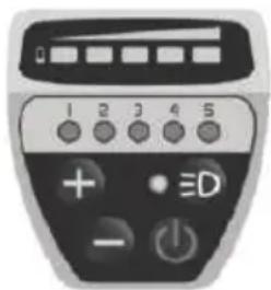
natural_image
Front view of a black-and-white remote control device with labeled buttons (no readable text or symbols beyond numeric labels)2. Fonctions
2.1 Bouton Start/Stop
1.1 Bouton DEMMARAGE/ ARRET
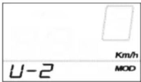
UNITES DE CONTROLE
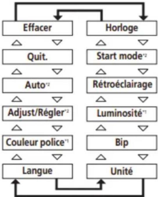
flowchart
graph TD
    A["Effacer"] --> B["Quit."]
    A --> C["Auto*2"]
    A --> D["Adjust/Régler*2"]
    A --> E["Couleur police*1"]
    A --> F["Langue"]
    G["Horloge"] --> H["Start mode*2"]
    G --> I["Rétroéclairage"]
    G --> J["Luminosité*1"]
    G --> K["Bip"]
    G --> L["Unité"]
    B --> A
    C --> A
    D --> A
    E --> A
    F --> A
    H --> A
    I --> A
    J --> A
    K --> A
    L --> A
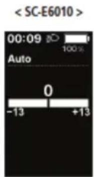
UNITES DE CONTROLE
[TOT] Distance cumulée


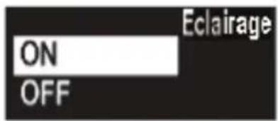
Éléments configurables/Description
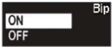


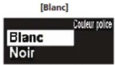
natural_image
Close-up of a black bicycle brake lever with illuminated indicator lights (no text or symbols visible)Bouton (1)
natural_image
Close-up of a black plastic component with a small circular annotation labeled '1' pointing to its edge (no readable text or symbols beyond the label)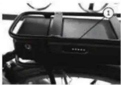
natural_image
Close-up of a black vehicle front bumper with visible branding and no readable text or symbols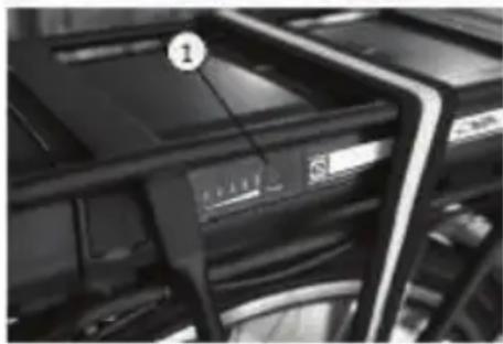
natural_image
Close-up of server racks with a numbered label pointing to a device (no readable text or symbols)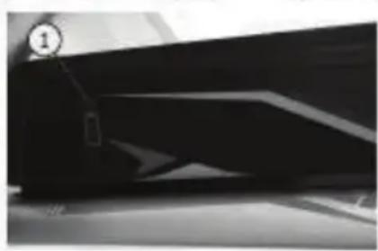
natural_image
Close-up of a dark, abstract geometric shape with no visible text or symbolsnatural_image
Close-up of a black plastic electronic component with a numbered label pointing to a feature (no readable text or symbols)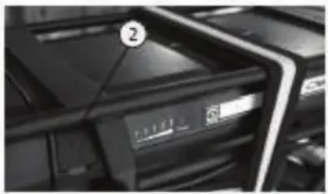
natural_image
Close-up of a black electronic device with a numbered label (2) on the top, showing internal components and no readable text or symbols.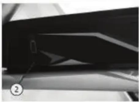
natural_image
Close-up of a dark, glossy surface with a numbered marker (2) pointing to a small object, possibly a device or component (no readable text or symbols)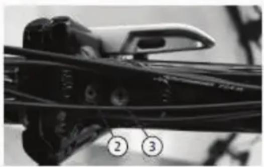
natural_image
Close-up of a mechanical component with numbered callouts (2 and 3) pointing to features, no readable text or symbols present.natural_image
Close-up of a black automotive vehicle front panel with visible branding and control knobs (no readable text or symbols)FOURCHE AVEC SUSPENSION
natural_image
Simple line drawing of a trash bin with crossed lines indicating no waste or discharge (no text or symbols)natural_image
Simple line drawing of a trash bin with crossed lines indicating no waste or discharge (no text or symbols)natural_image
Recycling symbol composed of five chasing arrows forming a triangle (no text or labels)electric moving green
Trevi S.P.A Strada Consolare Rimini-San Marino 62
47924 Rimini-Italy
Article Nr. 1093023
Trevi S.P.A. reserves the right to correct and make technical changes without prior notice