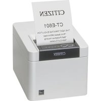
CTE601 - Printer CITIZEN - Free user manual and instructions
Find the device manual for free CTE601 CITIZEN in PDF.


| Product Type | Thermal line printer |
| Brand | Citizen |
| Model | CT-E601 |
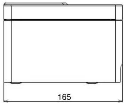
| Dimensions (L × D × H) | 125 × 165 × 108 mm |
| Weight | Approx. 1.2 kg |
| Power | AC adapter 24 V DC 2.1 A, input 100-240 V AC 50/60 Hz |
| Print method | Thermal line matrix |
| Maximum print speed | 350 mm/s |
| Print width | 72 mm (576 dots) default (adjustable) |
| Resolution | 203 dpi (8 dots/mm) |
| Supported paper widths | 80 mm and 58 mm |
| Interfaces | RS-232C, USB 2.0, Bluetooth 3.0/4.2, Ethernet 100BASE-TX, Wireless LAN IEEE 802.11a/b/g/n, Lightning (MFi) |
| Main features | Automatic cutter, paper jam sensor, Web/XML printing, power saving, 16 gray levels, 2D barcode support |
| Maintenance and cleaning | Clean the print head and platen with ethyl alcohol and a cotton swab. Wipe the case with a soft dry cloth. |
| Safety | Do not expose to moisture, flames or shocks. Unplug before maintenance. Do not touch the head after printing. |
| Spare parts and repairability | AC adapter (37AD5), separator for 58 mm paper, cable cover. Repair by an authorized Citizen Systems service center. |
| General information | Manual available in multiple languages. Compliant with ENERGY STAR standards. Warranty: contact your dealer. |
Frequently Asked Questions - CTE601 CITIZEN
User questions about CTE601 CITIZEN
0 question about this device. Answer the ones you know or ask your own.
Ask a new question about this device
Download the instructions for your Printer in PDF format for free! Find your manual CTE601 - CITIZEN and take your electronic device back in hand. On this page are published all the documents necessary for the use of your device. CTE601 by CITIZEN.
USER MANUAL CTE601 CITIZEN
LINE THERMAL PRINTER
MODEL CT-E601
User's Manual
Mode d'emploi
Benutzerhandbuch
Manuale dell'utente
Manual de Usuario
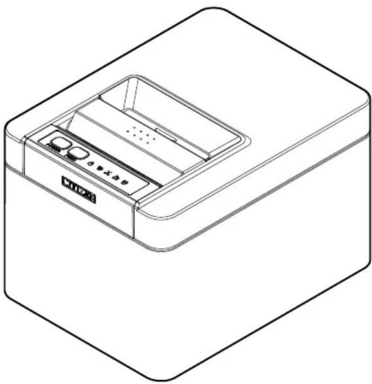
natural_image
Line drawing of a rectangular electronic device with internal compartments and ports (no text or symbols)If you want to dispose of this product, do not mix it with general household waste. There is a separate collection systems for used electronics products in accordance with legislation under the WEEE Directive and is effective only within European Union.

Compliance Statement for European Users
CE marking shows conformity to the following criteria and provisions:
Low Voltage Directive (2014/35/EU), EMC Directive (2014/30/EU), and RoHS directive (2011/65/EU)
Full text of the EU declaration of conformity is available at the following internet address:
http://www.citizen-systems.co.jp/en/printer/download/eu_doc.html
IMPORTANT: This equipment generates, uses, and can radiate radio frequency-energy and if not installed and used in accordance with the instruction manual, may cause interference to radio communications. It has been tested and found to comply with the limits for a Class A computing device pursuant to Subpart J of Part 15 of FCCRules, which are designed to provide reasonable protection against such interference when operated in a commercial environment. Operation of this equipment in a residential area is likely to cause interference, in which case the user at his own expense will be required to take whatever measures may be necessary to correct the interference.
CAUTION: Use shielded cable for this equipment.
Sicherheitshinweis
- Before using this product, be sure to read through this manual. After having read this manual, keep it in a safe, readily accessible place for future reference.
● The information contained herein is subject to change without prior notice. - Reproduction or transfer of part or all of this document in any means is prohibited without permission from Citizen Systems.
- Note that Citizen Systems is not responsible for any operation results regardless of omissions, errors, or misprints in this manual.
- Note that Citizen Systems is not responsible for any trouble caused as a result of using options or consumables that are not specified in this manual.
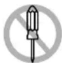
- Except explained elsewhere in this manual, do not attempt to service, disassemble, or repair this product.
- Note that Citizen Systems is not responsible for any damage attributable to incorrect operation/handling or improper operating environments that are not specified in this manual.
- Data is basically for temporary use and not stored for an extended period of time or permanently. Please note that Citizen Systems is not responsible for damage or lost profit resulting from the loss of data caused by accidents, repairs, tests or other occurrences.
- If you find omissions, errors, or have questions, please contact your Citizen Systems dealer.
- If you find any pages missing or out of order, contact your Citizen Systems dealer for a replacement.
Use of the Made for Apple badge means that an accessory has been designed to connect specifically to the Apple product(s) identified in the badge and has been certified by the developer to meet Apple performance standards.
Apple is not responsible for the operation of this device or its compliance with safety and regulatory standards.
Please note that the use of this accessory with an Apple product may affect wireless performance.
- Apple, Apple TV, Apple Watch, iPad, iPad Air, iPad Pro, iPhone, and Lightning are trademarks of Apple Inc., registered in the U.S. and other countries. tvOS is a trademark of Apple Inc. The trademark “iPhone” is used in Japan with a license from Aiphone K.K.
- EPSON and ESC/POS are registered trademarks of Seiko Epson Corporation.
-
QR Code is a registered trademark of DENSO WAVE INCORPORATED.
-
Ethernet is a registered trademark of Fuji Xerox Corporation.
- Bluetooth® is a registered trademark of Bluetooth-SIG Inc.
● CITIZEN is a registered trademark of Citizen Watch Co., Ltd.
● All other trademarks are the property of their respective owners. - Citizen Systems use these trademarks in accordance with the license of relevant owners.
Copyright© CITIZEN SYSTEMS JAPAN CO., LTD. 2021
SAFETY PRECAUTIONS...WHICH SHOULD BE STRICTLY OB- SERVED
Before using this product for the first time, carefully read these SAFETY PRECAUTIONS. Improper handling may result in accidents (fire, electric shock or injury).
In order to prevent injury to operators, third parties, or damage to property, special warning symbols are used in the User's Manual to indicate important items to be strictly observed.
- After having read this Manual keep it in a safe, readily accessible place for future reference.
- Some of the descriptions contained in this manual may not be relevant to some printer models.
The following describes the degree of hazard and damage that could occur if the printer is improperly operated by ignoring the instructions indicated by the warning symbols. Be sure to read this information carefully.

WARNING
Neglecting precautions indicated by this symbol may result in fatal or serious injury.

CAUTION
Neglecting precautions indicated by this symbol may result in injury or damage to property.

This symbol is used to alert your attention to important items.

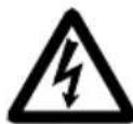
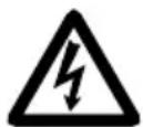
This symbol is used to alert you to the danger of electric shock or electrostatic damage.

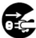
This symbol denotes a request to unplug the printer from the wall outlet.

This symbol is used to indicate that the power supply must be grounded.

This symbol is used to indicate useful information, such as procedures, instructions or the like.

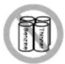
This symbol is used to indicate prohibited actions.
PRECAUTIONS ON PRINTER INSTALLATION

WARNING
■ Do not use or store this product in a place where it will be exposed to:
* Flames or moist air.
* Direct sunlight.
* Hot airflow or radiation from a heating device.
* Salty air or corrosive gases.
* Ill-ventilated atmosphere.
* Chemical reactions in a laboratory.
* Airborne oil, steel particles, or dust.
* Static electricity or strong magnetic fields.
■ These locations create the risk of printer damage, as well as product failure, overheating, emission of smoke, fire, or electric shock.
They can also result in fire or electric shocks and so should always be avoided.


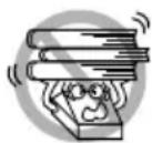
- Do not drop any foreign object nor spill liquid into the printer. Do not place any object on the printer either.
■ Do not drop any metallic object such as paper clips, pins or screws into the printer.
■ Do not place a flower vase, pot, or anything containing water on the printer.
■ Do not spill coffee, soft drinks, or any other liquid into the printer.
■ Do not spray insecticide or any other chemical liquid over the printer.
■ Dropping a metallic foreign object into the printer, may cause printer failure, fire, or electric shock.
Should it occur, immediately turn the printer off, unplug it from the supply outlet, and call your local Citizen Systems dealer.

■ Do not handle the printer in the following ways:
- Do not subject the printer to strong impacts or hard jolts (e.g., being stepped on, dropped or struck).
● Never attempt to disassemble or modify the printer.
■ These actions create the risk of printer damage, as well as product failure, overheating, emission of smoke, fire, or electric shock.
They can also result in fire or electric shocks and so should always be avoided.

WARNING
This device is not appropriate to be used where a child may be present. Install, store, or use the device where it cannot be reached by a child.
- Electric appliances could cause an unexpected injury or accident if they are handled or used improperly.
- Keep the power cord and signal cables out of the reach of children. Also children should not be allowed to gain access to any internal part of the printer.
- The plastic bag the printer came in must be disposed of properly or kept away from children. Wearing it over the head may lead to suffocation.

CAUTION
Do not use the printer under the following conditions.
- Avoid locations subject to vibration or instability.
● Avoid locations where the printer is not level.
◆ The printer may fall and cause an injury.
◆ The quality of printing may deteriorate.
- Do not obstruct the printer's air vents.
- Do not place anything on the printer.
- Do not cover or wrap the printer in cloth or blankets.
◆ Doing so could cause heat to build up and deform the case or start a fire.
- Avoid using the printer near a radio or TV set or from supplying it from the same electric outlet as these appliances.
- Avoid using the printer interconnected with a cable or cord that has no protection against noise.
(For interconnections, use shielded or a twisted pair of cables and ferrite cores, or other anti-noise devices.)
● Avoid using the printer with a device that is a strong source of noise.
The printer may have an adverse effect on nearby radio or TV transmissions. There may also be cases when nearby electrical appliances adversely influence the printer, causing data errors or malfunction.
- Installed in any orientation other than those specified.
◆ Malfunction, failure, or electric shock may result.
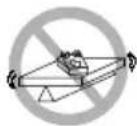
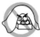
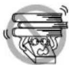
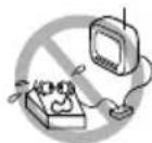

CAUTION
■ Connect the printer to a ground.
● Electric leakage may cause an electric shock.
- Do not connect the printer's ground to any of the following:
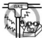
* Gas piping
● A gas explosion could result.
* Telephone line ground
* Lightning rod
- If lightning strikes a large surge of current may cause fire or shock.
* Water pipes
- Plastic water pipes should not be used for grounding. (Those approved by a Waterworks Department may be used.)
■ Before connecting or disconnecting the grounding lead to or from the printer, always unplug it from the electric outlet.

PRECAUTIONS IN HANDLING THE PRINTER

WARNING
Please observe the following precautions for power source and power cord:
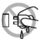
- Do not plug or unplug the power cord with a wet hand.
● Use the printer only at the specified supply voltage and frequency. - Use only the specified AC adapter with the printer.
- Use only the power cord that comes with the printer, and never use the supplied power cord with another device.
- Check to make sure that the supply outlet from which the printer is powered has a sufficient capacity.
- Do not supply the printer from a power strip or current tap shared with other appliances.
- Do not plug the power cord into an electric outlet with dust or debris left on the plug.
- Do not use a deformed or damaged power cord.
- Do not move the printer while its power is on.
◆ Neglecting to handle it properly may result in printer failure, emission of smoke, fire, or electric shock.
◆ An overload may cause the power cord to overheat, catch fire, or the circuit breaker to trip.
- Do not allow anything to rest on the power cord. Do not place the printer where the power cord may be stepped on.
- Do not subject the power cord to severe bending, twisting, or pulling. Do not carry the product while it is in this state either.
- Do not attempt to modify the power cord unnecessarily.
- Do not place the power cord near any heating device.
◆ Neglecting these cautions may cause wires or insulation to break, which could result in electric leakage, electric shock, or printer failure. If the power cord sustains damage, contact your Citizen Systems dealer.
- Do not leave things around the electric outlet.
● Supply power to the printer from a convenient electric outlet, readily accessible in an emergency.
◆ Pull the plug to immediately shut it down in an emergency.
- Insert the power plug fully into the outlet.
- If the printer will not be used for a long time, disconnect it from its electric outlet.


WARNING
- Hold the plug and connector when plugging or unplugging the power cord or signal cable after turning off the printer and the appliance connected to it.

CAUTION
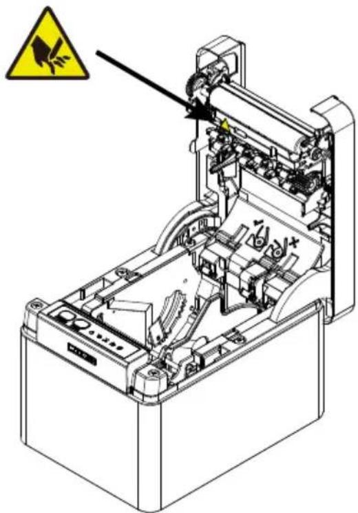
Caution label is attached in the position shown in the following figure. Carefully read the handling precautions before using the printer.
These labels indicate that the head becomes hot, so touching it may cause burns, and touching the auto cutter when opening the paper cover may cause cuts on hands.
natural_image
Technical line drawing of an electronic device with a warning symbol (no text or labels present)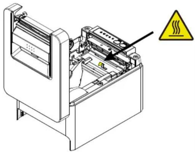
natural_image
Technical line drawing of an industrial machine with a warning symbol (no text or labels present)Do not transport this printer with the paper roll inside.
● Printer failure or damage may occur.
To prevent possible malfunction or failure observe the following.
- Do not open the paper cover during printing.
- Avoid operating the printer without paper properly loaded.
● Avoid the use of paper not complying with specifications.
◆ May result in poor print quality.
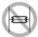
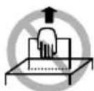
● Avoid using torn pieces of paper or paper spliced with plastic adhesive tape.
- Avoid forcibly pulling already loaded paper by hand.
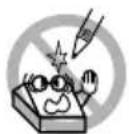
- Avoid using a sharp pointed device to operate panel buttons.

CAUTION
■ Be sure to firmly insert the cable plugs into their mating sockets.
- A cross connection may damage the printer's internal electronics or the host system's hardware.
■ Only use the printer with devices that have designated solenoid specifications for the cash drawer interface connector.
● Neglecting this caution may result in malfunction or failure.
To prevent injury and printer failures from worsening, observe the following:
- Do not touch the printing surface of the thermal head.
- Do not touch any of the moving parts (e.g., paper cutter, gears, active electric parts) while the printer is working.
- In case of trouble do not attempt to repair the printer. Ask Citizen Systems service for repair.
- Be careful that the covers do not pinch your hands or fingers.
- Be careful of the sharp edges on the printer. Do not allow them to injure you or damage property.
◆ May result in electric shock, burn, or injury.
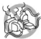
If the printer emits smoke, an odd smell, or unusual noise while printing, immediately abort the current print session and unplug the printer from the electric outlet.

DAILY MAINTENANCE
Observe the following precautions for daily maintenance.
- When cleaning the printer, always turn it off and unplug it from the electric outlet.
● Using a soft and dry cloth, wipe off any dirt or dust on the surface of the case.
If it is badly soiled, wipe it off with a dish towel wetted with water and wrung out hard.
Never use organic solvents such as thinner, trichloroethylene, benzene, ketone, etc., or chemically treated cloth.
● To remove paper dust, use a soft brush.

CAUTION
The thermal head is at a dangerously high temperature immediately after printing.
Allow it to cool off before starting maintenance work.
1. GENERAL OUTLINE ...... 19
1.1 Features ...... 19
1.2 Unpacking 21
1.3 Model Classification 22
1.4 Basic Specifications ...... 22
2. EXPLANATION OF PRINTER PARTS 25
2.1 Printer Appearance 25
2.2 Inside the Paper Cover 28
2.3 Other Built-in Functions 30
3. SETUP 32
3.1 Connecting the AC Power Cord 32
3.2 Serial Interface Board 33
3.3 USB Interface 35
3.4 Bluetooth Interface Board 36
3.5 Bluetooth USB host interface board 39
3.6 Ethernet (LAN)/Wireless LAN Interface Board 47
3.7 Lightning USB host interface board 54
3.8 USB Power Supply Port 60
3.9 Connecting the Cash Drawer 62
3.10 Precautions for Installing the Printer 64
3.11 Adjusting the Paper Near-end Sensor 65
3.12 Loading Paper 66
3.13 58-mm Width Roll Paper Partition 69
3.14 Mounting the Cable Cover 70
3.15 Precautions for Creating Applications and Practical Operations 71
3.16 Download Site for Various Electronic Files 71
4. MAINTENANCE AND TROUBLESHOOTING 72
4.1 Periodic Cleaning 72
4.2 Clearing a Cutter Error 74
4.3 Canceling print stop caused by a paper jam 74
4.4 Self Test 75
4.5 Hexadecimal Dump Printing 76
4.6 Error Indications ...... 77
4.7 Paper Jams 79
4.8 Precautions for Performing Printing for Which Printing Speed Changes 79
5. OTHER 80
5.1 External Views and Dimensions 80
5.2 Printing Paper 81
5.3 Manual Setting of Memory Switches 83
The CT-E601 line thermal printer series is designed for use with a broad array of terminal equipment including data, POS, and kitchen terminals.
These printers have extensive features so they can be used in a wide range of applications.
1.1 Features
● High-speed printing at up to 350 mm/sec possible
● Silver ion-blended plastic is used for the exterior
- Stylish design
● Compact size with the lowest possible height
● Support for paper widths of 80 mm and 58 mm
● High-speed cutter employed
● Equipped the printing stop sensor by paper jam
● Equipped with a paper anti-curling function
- USB interface included as standard
● Equipped with a standard USB power supply port
● Energy saving function (ENERGY STAR compliant)
- Interchangeable interface board
● XML/Web print function included (wired LAN or wireless LAN model)
- USB host function capable of controlling peripheral devices included (wired LAN, Bluetooth or Lightning USB host model)
● The Lightning model can transmit data even during fast charging of Apple devices
● Printer status and errors indicated by five LEDs
● Built-in drawer kick interface
- USB-linked power OFF function available
● 16 level greyscale and clear printing
● Paper saving function available
● Support for the JIS X0213 third and fourth level Kanji character sets
- Support for the simplified and traditional Chinese character sets and Hangul character set
● Support for UTF-8 using commands
● Various customizations using the memory switches possible
- User created characters and logos can be saved in the user memory
● Support for barcodes including 2D barcodes - Apple MFi certified Bluetooth and USB (Lightning) communication support (Bluetooth model, Lightning model)
1.2 Unpacking
Make sure the following items are included with your printer.
| NAME | QUANTITY | ILLUSTRATION |
| Printer 1 | 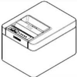 | |
| AC Adapter (37AD5) 1 | 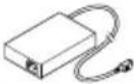 | |
| AC power cord 1 | 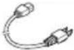 | |
| Quick Start Guide 2 |  |
1.3 Model Classification
Model numbers indicate printer features according to the following system.

1: Model name
2: Interface
RS: Serial RS-232C+USB
ET: Ethernet+USB
HET: Ethernet (USB host function) + USB
BT: Bluetooth+USB
HBT: Bluetooth (USB host function)
WF: Wireless LAN+Ethernet+USB
LT: Lightning (USB host function) + USB
NN:USB
3: Market
U: North America
E: Europe
4: Body case color
WH: Pure white
BK: Black
Contact us in advance for special combinations, some of which may not be available.
1.4 Basic Specifications
Notes:
*1 The number of printable columns is selected using a memory switch.
| Item | Specifications | |||
| Model CT-E601 | ||||
| Print method Line thermal dot print method | ||||
| Print widths 72 mm/576 dots, 68.25 mm/546 dots, 64 mm/512 dots, 52.5 mm/420 dots, 48.75 mm/390 dots, 48 mm/384 dots, 45 mm/360 dots, factory default 72 mm | ||||
| Dot density 8 × 8 dots/mm (203 dpi) | ||||
| Print Speed 350 mm/sec (maximum speed, print density level 100%, 2800 dot lines/sec) | ||||
| Item Specifications | ||||
| Number of print columns *1 | Font Maximum | m number of characters (columns) / 80 mm | Maximum number of characters (columns) / 58 mm | Dot configuration (dots) |
| Font A 48 35 12 × 24 | ||||
| Font B 64 46 9 × 24 | ||||
| Font C 72 52 8 × 16 | ||||
| Character size *2 Font A:1 | 50×3.00 mm, Font B:1.13×3.00 mm, Font C:1.00×2.00 mm | |||
| Character type Alphanumeric characters, international characters, PC437/850/852/857/858/860/863/864/865/866, WPC1252, WPC1258, Katakana, ThaiCode 11/18 (1Pass/3Pass), TCVN-3, Kanji (JIS first, second, third, and fourth level), Kana, extended characters, JIS X0213, GB18030, BIG5, KS Hangul, EUC Hangul | ||||
| User memory 384 KB (capable of storing user-defined characters and logos) | ||||
| Bar code types UPC-A/E, JAN(EAN) 13 digits/8 digits, ITF, CODE39, CODE128, CODABAR (NW-7), CODE93, PDF417, QR Code, GS1-DataBar | ||||
| Line spacing 4.25 mm (1/6 inch) (Variable by command) | ||||
| Paper roll Roll paper: 80 mm x max. ø83 mm Paper thickness: 53 to 85 μm (paper roll inner diameter 12 mm / outer diameter 18 mm) | ||||
| Interface Serial (RS-232C standard), USB, Bluetooth+USB, LAN, wireless LAN+LAN, LAN (USB host function) (USB 2 port)), Bluetooth (USB host function) (USB 2 port)), Lightning (USB host function (USB3 port)) | ||||
| Ethernet | 100BASE-TX/10BASE-T | |||
| Wireless LAN | IEEE802.11n, IEEE802.11a, IEEE802.11g, IEEE802.11b | |||
| Bluetooth Version: Bluetooth 3.0 + EDR Profile: SPP (Serial Port Protocol), iAP (iPod Accessory Protocol) Power class: Class2 | ||||
| Bluetooth (USB host function) | Version: Bluetooth 4.2 + EDR Profile: SPP (Serial Port Protocol), iAP2 (iPod Accessory Protocol) Power class: Class2 | |||
| USB power supply port | Max. 2.1 A | |||
| Cash drawer kick-out | Supports 2 cash drawers | |||
| Input buffer 4 K bytes/45 bytes | ||||
| Supply voltage DC 24 V ±5% | ||||
| Power consumption | Approx. 50 W (when printing), approx. 1 W (in standby mode), approx. 0.3 W (with power off) | |||
| AC Adapter (37AD5) | Rated input: AC 100 to 240 V, 50/60 Hz, 150 VA Rated output: DC 24 V, 2.1 A | |||
| Weight | Approximately 1.2 kg | |||
| Outside dimensions | 125 (W) × 165 (D) × 108 (H) mm | |||
| Operating temperature and humidity | 5 to 45 °C, 10 to 90% RH (no condensation) | |||
| Storage temperature and humidity | -20 to 60 °C, 10 to 90% RH (no condensation) | |||
| Reliability | Print head life: 200 km, 200 million pulses (room temperature, room humidity, specified recommended paper, specified paper thickness), Auto cutter life: 2 million cuts (3-inch), 1.5 million cuts (2-inch) (room temperature, room humidity, specified recommended paper, specified paper thickness) | |||
| Safety standard *3 | UL, FCC Class A, CE Marking | |||
The numbers of columns noted in this table refer to typical models. The number of columns varies depending on specifications.
*2 Characters appear small because the dimensions include a blank area surrounding each character.
*3 This standard applies when our AC Adapter (37AD5) is used.
2. EXPLANATION OF PRINTER PARTS
2.1 Printer Appearance
Names of parts
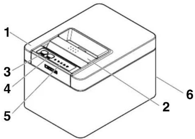
1: Paper cover
Open to load paper.
Also open to clear a cutter error.

Refer to 4.2 Clearing a Cutter Error
2: Cover open lever
Use to open the paper cover.
3: POWER button
Hold down two or three seconds to switch power on or off.
4: FEED button
Press this button to feed paper.
In case of a cutter error, press the FEED button with the paper cover closed after removing the cause.
The printer enters the mode for setting memory switches and running self test.

Refer to 4.4 Self Test

Refer to 5.3 Manual Setting of Memory Switches
5: Operation panel
6: Rear connectors
Operation panel
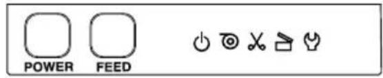
The operation panel has five LEDs and two buttons.
| LED name Color Description | |||
 | POWER LED Green | Lights when the power is on, turns off when the power is off. | |
 | PAPER LED Green | Lights or flashes when no paper or low paper is detected.May also light or flash when other abnormalities are detected. | |
 | CUTTER LED Green | Flashes when a cutter error is detected.May also light or flash when other abnormalities are detected. | |
 | COVER LED Green | Lights or flashes when an open paper cover is detected.May also light or flash when other abnormalities are detected. | |
 | SERVICE LED Orange | Flashes when an unrecoverable printer abnormality is detected. | |

Refer to 4.6 Error Indications
Rear connectors (serial interface example)
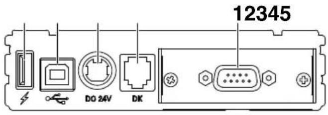
1: Interface connector (serial, USB, etc.)
Connect to the interface cable.
2: Cash drawer kick-out connector
Connect to the cable from the cash drawer.
3: Power connector
Connect to the AC adapter cable.
4: USB connector
5: USB power supply port
Supply power to a USB device.
2.2 Inside the Paper Cover
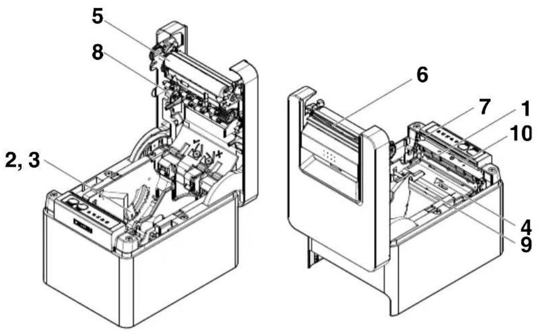
1: Print head (thermal)
Prints characters and graphic data on paper (paper rolls).
2: Paper near-end (PNE) sensor
Detects when the paper is near the end of the roll. Adjust the position of the sensor to determine when it detects the end of the paper is near.
3: Button to change paper near-end sensor
Change the position of the paper near-end sensor to match the paper being used.

Refer to 3.11 Adjusting the Paper Near-end Sensor
4: Paper end (PE) sensor
Detects when there is no paper. Printing stops when this sensor detects there is no paper.
5: Platen
Feeds the paper.
Do not remove the platen except to do maintenance.
6: Auto cutter
Cuts the paper.

Refer to 5.3 Manual Setting of Memory Switches
7: Manual cutter
For cutting the paper manually when printing is finished.
8: Paper anti-curling roller
Roller for reducing the warp of the paper.
9: Paper anti-curling damper
Damper for reducing the warp of the paper.
10: Paper jamming sensor
Sensor for detecting paper jam and stopping the printing.
Notes
The anti-curling roller and anti-curling damper do not straighten the paper completely.
2.3 Other Built-in Functions
- Buzzer
Buzzes when errors occur or when operations or command operations are performed.

Refer to 4.6 Error Indications
- User memory
You can save user-defined logo and character data in this memory. Data remains stored in this memory even if the printer is turned off. For information on how to save data, refer to the Command Reference.
- Memory switch
Setting of various kinds of functions can be stored in memory. Settings remain stored in the memory even if the printer is turned off.
- USB-linked power OFF (When MSW6-3 of memory switch is set to ON)
When the printer is connected to PC by USB, the printer becomes the state of USB-linked power OFF after 3 seconds when PC power off or USB connection lost.
This mode is canceled when the PC is turned back on or when a USB connection is established.
Notes
■ Since the POWER LED is unlit when the state of USB-linked power OFF, it cannot be identified from the power OFF.
- Pressing the POWER button while the state of USB-linked power OFF turns on power normally.
● Paper saving functions
Memory switches MSW8-3 through MSW8-4 can be used to configure the settings below, which save paper.
- Top margin suppression
The printer back feeds the paper before printing which reduces the blank space at the top edge of the paper.
The back feed amount can be specified.
Automatically compresses the linefeed amount between lines. The compression ratio can be specified.
- Line gap reduce

CAUTION
Remove the partially cut paper before performing back feed for starting printing.
The cut paper may be torn off in the next printing process, which may cause a problem.
● Auto side shift (MSW8-6)
This function dissipates heat load during frequent heat generation by a vertical ruled line or other specific head heating element.
If no data is received within 15 seconds after each cut or print, the print position is automatically slid N* dots to the right. The original print position is returned to at the next slide timing.
* N is the MSW8-6 setting value.
Notes
If the right margin is too narrow, this may result in some print characters being cut off.
■ This function is disabled under initial settings.
■ To enable this function, use MSW8-6 to specify an appropriate value for the maximum slide amount.
3.1 Connecting the AC Power Cord
- Turn off the power.
- Connect the power connector to the AC adapter cable connector.
Next, connect the AC power cord to the AC inlet, and insert the plug into an electric outlet.
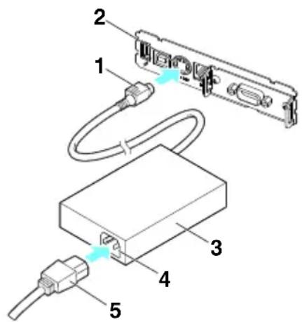
- Cable connector
- Power connector
- AC adapter
- AC inlet
- AC power cord

CAUTION
■ Use only the specified AC adapter.
- Always hold the AC adapter's cable connector by the connector when removing or inserting it.
■ Use an AC power source that does not also supply power to equipment that generates electromagnetic noise.
■ Pulling on the AC power cord may damage it, cause a fire, electric shock, or break a wire.
If a lightning storm is approaching, unplug the AC power cord from the electric outlet. A lightning strike may cause a fire or electric shock.
- Keep the AC power cord away from heat generating appliances. The insulation on the AC power cord may melt and cause a fire or electric shock.
■ If the printer is not going to be used for a long time, unplug the AC power cord from the electric outlet.
■ Place the AC power cord so that people do not trip on it.
3.2 Serial Interface Board
Data can be exchanged by serial communication.
Connecting the Interface Cable
-
Turn off the power.
-
Confirm the orientation of the interface cable and connect it to the port.
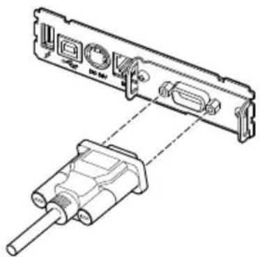
natural_image
Technical line drawing of a device's internal components, showing a connector with ports and a cable (no text or symbols)- Insert the other connector firmly into the interface port of the host computer.

CAUTION
■ When disconnecting the cable, always hold the connector.
■ Place the interface cable so that people do not trip on it.
Notes
Do not connect multiple interfaces at the same time.
Use a serial cable with the connection layout shown below.
9-pin (female) - 9-pin (female) cable
PrinterPC
| Signal | Pin | Pin | Signal | ||
| RXD 2 | 2 | RXD | |||
| TXD 3 | 3 | TXD | |||
| DTR 4 | 4 | DTR | |||
| SG 5 | 5 | SG | |||
| DSR 6 | 6 | DSR | |||
| RTS 7 | 7 | RTS | |||
| CTS 8 | 8 | CTS |
3.3 USB Interface
Data can be exchanged by USB communication.
Specifications
Standard USB 2.0 specification-compliant
Communication speed \$upports 12 Mbps (Full-Speed) transfer
Connecting the Interface Cable
- Turn off the power.
- Confirm the orientation of the interface cable and connect it to the port.
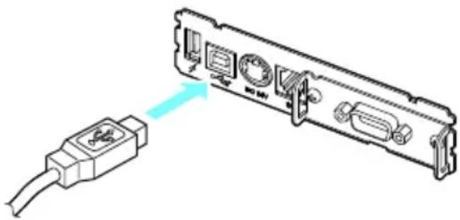
- Insert the other connector firmly into the interface port of the host computer.

CAUTION
■ When disconnecting the cable, always hold the connector.
■ Place the interface cable so that people do not trip on it.
■ Be careful not to insert the USB cable into the cash drawer kick-out connector.
Notes
■ Do not connect multiple interfaces at the same time.
■ To connect more than one printer to a single computer by USB, you must change the serial number of the USB interface.
■ There are models with a USB port on the interface board side.
With such a model, do not connect USB cables to both the printer main unit side and interface board side.
If USB cables are connected to both, priority will be given to communication of the one connected to the port on the main unit side.
3.4 Bluetooth Interface Board
Names of parts
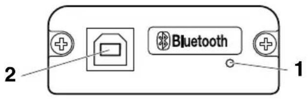
1. Status LED
The Bluetooth communication/connection/error status is indicated by this LED.
2. USB connector
Data can be exchanged by USB communication.
Notes
When using this interface board as a USB interface, do not connect USB cables to both the main unit side and interface board side.
If USB cables are connected to both, priority will be given to communication of the one connected to the connector on the main unit side.
Bluetooth status LED
| Status | Description LED | Status |
| Detection standby (Discoverable) | Standing by for detection and connection |  |
| Connection standby (Connectable) | Standing by for connection |  |
| iOS connection Data | session unopened |  |
| Communicating iOS: | data session openedOther OS: connection established and communication in progress |  |
| Error Error or settings | being configured | Unlit |
Pairing operation
You need to perform the operations below the first time you establish a Bluetooth connection for Bluetooth data communication.
- Detect Bluetooth devices
- Configure pairing settings
1: Detecting Bluetooth devices
Confirm that Bluetooth is enabled on the host PC before searching for Bluetooth devices.
This product will show up as "CT-E601_XX"(XX is last 2 digits of unique BD address.) when it is detected.
Select this product from among the detected devices.
Note: You can search for devices and change the names.
When memory switch MSW13-5 is set to "No Response," nothing is displayed by device detection.
You can temporarily switch this setting to device detection (detect mode) by opening the paper cover and holding down the FEED button for two seconds. Detect mode is exited when the connection between the host PC is terminated.
2: Configuring pairing settings
Normally, selecting the printer during device detection will transition directly to pairing settings.
Notes
Some host PC configurations and models may not transition directly to pairing settings after the printer is selected during device detection.
The operation required to configure pairing settings depends on whether SSP (secure simple pairing) is enabled on the host PC.
If SSP is enabled on the host PC, pairing can be achieved without additional operations.
If SSP is disabled on the host PC, you will be prompted to input a passkey.
Input the passkey as described below.
Passkey
Last four digits of the address on the self test printout (Letters A through F are upper-case)
Example: If the address is 01:23:45:67:89:AB the passkey is 89AB.
If you delete paring information from the host PC without deleting the corresponding pairing information on the printer, the printer may not show up if you detect devices again with the host PC.
To delete printer pairing information, open the paper cover and then hold down the FEED button for five seconds.
Deleting pairing information on the printer will put the printer into discovery mode.
Auto reconnection
With iOS device Bluetooth communication, a connection between a paired iOS device and the printer is not automatically restored after it is lost. However, when auto reconnection is enabled, the printer tries to reconnect with an iOS device after two-way communication is enabled and automatically restores the connection.
Notes
This function is enabled when shipped from the factory. (MSW13-6)
Auto reconnection can take some time to connect when the host is not an iOS device.
■ Even if the partner device is an iOS device, the conditions below can interfere with the auto reconnection function.
- When you want Bluetooth communication to cut off after printing is complete
- When there are multiple iOS devices printing on the same printer
Under such conditions, disable auto reconnection.
Enabling and disabling auto reconnect
During self test, press the FEED button 3 times -> Auto reconnect = Valid
During self test, press the FEED button 4 times -> Auto reconnect = Invalid
At the end of self test, new setting will be printed as Auto reconnect [Valid] or [Invalid].

Refer to 4.4 Self Test
3.5 Bluetooth USB host interface board
In addition to printer control via Bluetooth communication, Bluetooth USB host interfaces can control peripheral devices connected via a USB port.
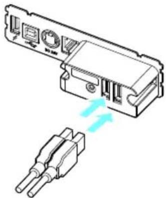
Connecting a Peripheral Device
- Turn off the power.
- Connect the cable of a peripheral device to this port.
natural_image
Diagram of a device component with two connectors and a light blue arrow indicating direction (no text or symbols)Notes
A peripheral device cannot be controlled if it is connected to the USB power supply port. Be sure to connect it to the USB port of the interface board.
Connecting a USB Device
The function assigned to each USB port differs.
Connect the USB device to be connected to the correct place in reference to the following figure.
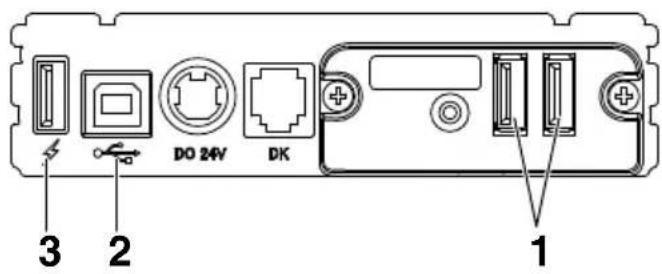
1: For peripheral device control
Connect a peripheral device.
The connected peripheral device can be controlled.
2: For host computer communication
Connect with a host computer.
The printer and host computer will communicate via USB.

Refer to 3.3 USB Interface
3: For supplying power
Connect a mobile device or other USB device.
Power can be supplied to a connected USB device.
* This port does not support USB data communication.

Refer to 3.8 USB Power Supply Port
Names of parts
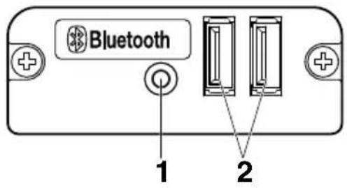
1: Panel button
Control this interface board.
2: USB 2 port
Connect a peripheral device.
Notes
■ Only connect peripheral devices specified by our company to the USB port.
■ Only plug in/remove peripheral devices when the printer power is turned off.
Pairing operation
You need to perform the operations below the first time you establish a Bluetooth connection for Bluetooth data communication.
- Detect Bluetooth devices
- Configure pairing settings
1: Detecting Bluetooth devices
Confirm that Bluetooth is enabled on the host PC before searching for Bluetooth devices.
This product will show up as "CT-E601_XX"(XX is last 2 digits of unique BD address.) when it is detected.
Select this product from among the detected devices.
Note: You can search for devices and change the names.
When memory switch MSW13-5 is set to "No Response," nothing is displayed by device detection.
With these settings, pressing and holding the panel button for at least three seconds and then pressing it twice more places the product temporarily in a state where it will be found in device searching (discovery mode).
Discovery mode cancels when the product is connected to a host PC.
2: Configuring pairing settings
Normally, selecting the printer during device detection will transition directly to pairing settings.
Notes
Some host PC configurations and models may not transition directly to pairing settings after the printer is selected during device detection.
The operation required to configure pairing settings depends on whether SSP (secure simple pairing) is enabled on the host PC.
If SSP is enabled on the host PC, pairing can be achieved without additional operations.
If SSP is disabled on the host PC, you will be prompted to input a passkey.
Input the passkey as described below.
Passkey
Last four digits of the address on the self test printout (Letters A through F are uppercase)
Example: If the address is 01:23:45:67:89:AB the passkey is 89AB.
If you delete paring information from the host PC without deleting the corresponding pairing information on the printer, the printer may not show up if you detect devices again with the host PC.
When deleting pairing information, press and hold the panel button for at least three seconds, and after the buzzer sounds, press it four more times.
If successful, "Erase Bonded Device" is printed.
Deleting pairing information on the printer will put the printer into discovery mode.
Auto reconnection
With iOS device Bluetooth communication, a connection between a paired iOS device and the printer is not automatically restored after it is lost. However, when auto reconnection is enabled, the printer tries to reconnect with an iOS device after two-way communication is enabled and automatically restores the connection.
Notes
■ This function is enabled when shipped from the factory. (MSW13-6)
Auto reconnection can take some time to connect when the host is not an iOS device.
■ Even if the partner device is an iOS device, the conditions below can interfere with the auto reconnection function.
- When you want Bluetooth communication to cut off after printing is complete
- When there are multiple iOS devices printing on the same printer
Under such conditions, disable auto reconnection.
Enabling and disabling auto reconnect
During self test, press the FEED button 3 times -> Auto reconnect = Valid
During self test, press the FEED button 4 times -> Auto reconnect = Invalid
At the end of self test, new setting will be printed as Auto reconnect [Valid] or [Invalid].

Refer to 4.4 Self Test
Panel button operation
Use the panel button on the rear of the Bluetooth board to operate this board.
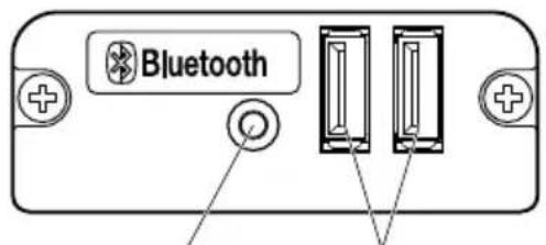
Panel button USB port
● BT device search (MSW13-5) settings
- Press and hold the panel button to turn on printer power.
- Press the panel button within one second after starting the printer.
The setting changes in accordance with the number of times you press the panel button.
Two presses: Discovery possible
Three presses: No response
After these operations the printer restarts.
● Print the interface board state
After starting the printer, pressing the panel button once prints the interface board state.
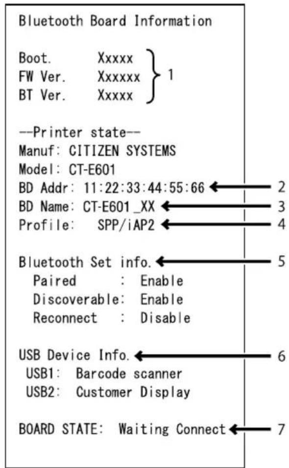
Print example
- Board firmware version
- Address of equipped Bluetooth module
- Bluetooth name
- Response profile in Bluetooth transmission
- Bluetooth setting state
- Name of connected USB device ("No connection" is displayed when there is no connection)
- Board status
3.6 Ethernet (LAN)/Wireless LAN Interface Board
This section provides an overview of the interface board. For details on this board, including explanations about the USB host function and XML peripheral device support, refer to the separate manual.
Connecting the Interface Cable
- Turn off the power.
- Confirm the orientation of the interface cable and connect it to the port.
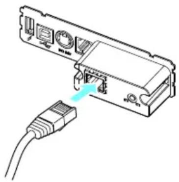
natural_image
Diagram of an electronic device showing a connector with ports and a cable inserted (no text or symbols)- Connect the other connector to a hub, router, or similar device.

CAUTION
■ When disconnecting the cable, always hold the connector.
■ Place the interface cable so that people do not trip on it.
- Hold the connector of the LAN cable perpendicular and straight when connecting or disconnecting it. Doing it at an angle may cause the connector to misconnect.
Notes
Do not connect multiple interfaces at the same time.
Connecting a Peripheral Device
-
Turn off the power.
-
Connect the cable of a peripheral device to this port.
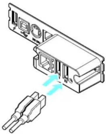
natural_image
Technical diagram of an electronic device showing a connector with two pins and a blue arrow indicating direction (no text or symbols present)Notes
A peripheral device cannot be controlled if it is connected to the USB power supply port. Be sure to connect it to the USB port of the interface board.
Connecting the wireless LAN adapter
-
Turn off the power.
-
Connect the wireless LAN adapter to the connector.
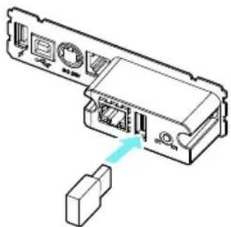
natural_image
Diagram of an electronic device showing a connector with ports and a cable outlet (no text or labels)Notes
The wireless LAN cannot be used when connected to the USB power supply connector. Be sure to connect it to the USB connector on the interface board.
Connecting a USB Device
The function assigned to each USB port differs.
Connect the USB device to be connected to the correct place in reference to the following figure.
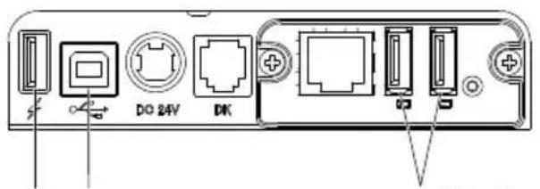
123 4
Ethernet/Wireless LAN
USB host model
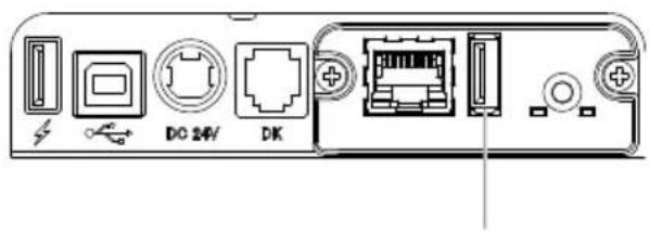
Wireless LAN
1: For peripheral device control and wireless LAN adapter connection
Connects the peripheral devices and wireless LAN adapter.
You can connect to either the left or right USB port.
Even when a wireless LAN adapter is connected, you can connect peripheral devices to available ports.
2: For host computer communication
Connect with a host computer.
The printer and host computer will communicate via USB.

Refer to 3.3 USB Interface
3: For supplying power
Connect a mobile device or other USB device.
Power can be supplied to a connected USB device.
* This port does not support USB data communication.

Refer to 3.8 USB Power Supply Port
4: For wireless LAN adapter connection
Connect a wireless LAN adapter.
A wireless LAN adapter must be connected in order to perform wireless LAN communication.
Panel button operation
Board operations are performed using the panel button on the rear of the LAN board.
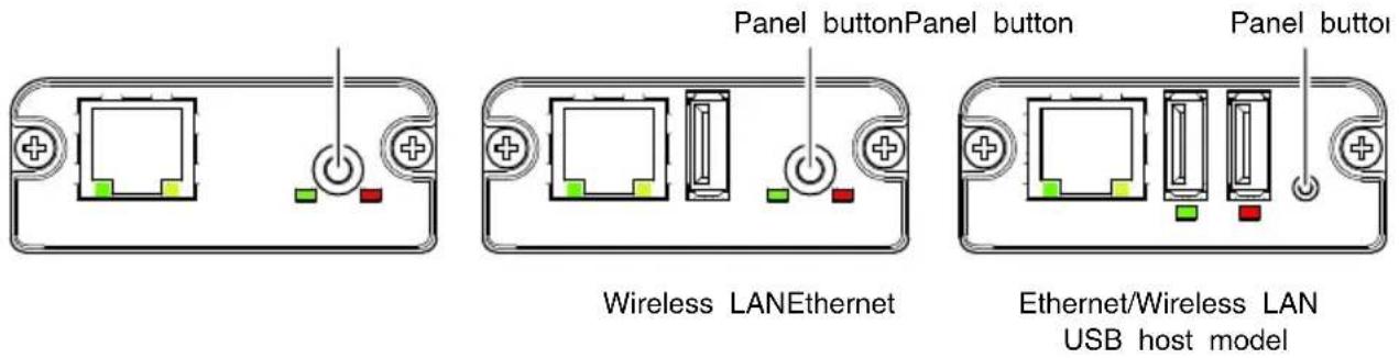
● Enabling LAN connection
Turn on the printer. Operation of this board will start about 20 seconds later.
● Printing LAN setup information
Press the panel button.
- Entering setting mode
Hold down the panel button. A buzzer will sound once to indicate that setting mode has been entered.
- You can use setting mode to read factory settings.
- If no operation is performed for 3 seconds in configuration mode, the mode switches back to normal mode.
- Returning to factory settings
Enter the board setting mode, and then hold down the panel button. This returns the board to its factory settings.
Notes
The board will automatically restart after this operation is complete. After clearing settings, you will need to re-configure network settings.
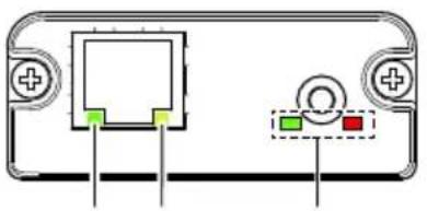
LED Functions
The tables below explain how to interpret LED indications.
natural_image
Diagram of a device rear panel with ports and indicator lights (no text or symbols)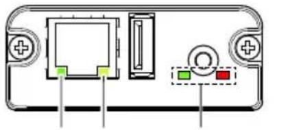
natural_image
Diagram of a device rear panel with ports and indicator lights (no text or symbols)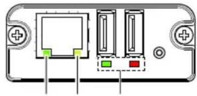
natural_image
Diagram of a device rear panel with ports and connectors (no text or symbols)1 2 3 1 2 31 2 3
Wireless LANEthernet Ethernet/Wireless LAN
USB host model
1: Wired LAN transmission speed
| Transmission speed LED (green) | |
| 100 Mbps Lit | |
| 10 Mbps/Not connected Unlit | |
2: Wired LAN connection/transmission status
| Connection status LED (yellow) | |
| Connected Lit | |
| Not connected | Unlit |
| Data transmission in progress | Flashing |
3: Wired/Wireless LAN status
| Connection status | LED (green) | LED (red) | Description | |
| No printer connection | Unlit | — | Board is not connected with a printer. | |
| Printer con- nection | No network con- nection | Lit | Unlit Board | is connected with a printer. |
| Connected by wired LAN | Lit | Flashing (1-second cycle) | Getting an IP address from the DHCP server over wired LAN. | |
| Wired LAN opera- tion | Lit | Lit | Network operation being performed over wired LAN. | |
| Connected by wireless LAN * | Flashing (2-second cycle) | Flashing (1-second cycle) | Connecting to an access point or get- ting an IP address from the DHCP serv- er over wireless LAN. | |
| Wireless LAN op- eration * | Flashing (2-second cycle) | Lit | Network operation being performed over wireless LAN. | |
| Resource error | Alternate flashing (1-second cycle) | Board is unable to operate normally. | ||
| System error | Alternate flashing (0.2-sec- ond cycle) | Board is unable to operate normally. | ||
* Only when using wireless LAN
Web Manager
The interface board has a Web Manager function that can be used to connect to the board with a web browser and change board settings.
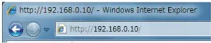
Starting up Web Manager
- Start up a web browser.
- In the address field, input the board's IP address and then press [Enter].
HOME Screen
This is the Web manager home screen.
The following screen is an example for a wireless LAN.
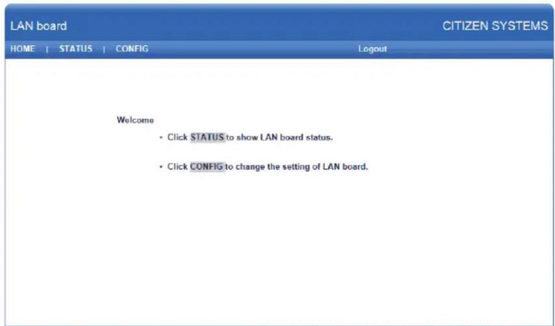
Copyright © 2012 CITIZEN SYSTEMS JAPAN CO.,LTD. All rights reserved.
Here, press the [CONFIG] button.
CONFIG Screen
This will display the Login dialog box shown below. Log in as an administrator and then configure interface board settings.
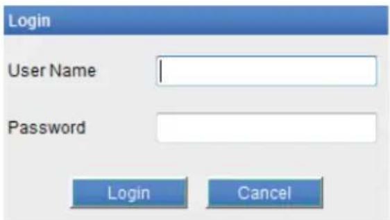
- User Name Input a board administrator user name. (Initial setting: admin)
- Password Input the administrator user password. (Initial setting: admin)
- [Login] button After inputting an administrator user name and password, click the [Login] button. This displays the setting screen. For details about settings, refer to the separate manual.
3.7 Lightning USB host interface board
In addition to printer control via USB (Lightning) communication, Lightning USB host interfaces can control peripheral devices connected via a USB port.
For Apple products with a USB Type-C connector, such as the iPad Pro, it is possible to use the same function by using USB Type-A - Type-C cable.
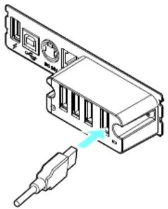
Connecting the Interface Cable
- Turn off the power.
- Confirm the orientation of the interface cable and connect it to the port.
natural_image
Technical line drawing of an electronic device rear panel with a connector inserted (no text or symbols)- Connect the other connector to the interface connector of an Apple device.

CAUTION
■ When disconnecting the cable, always hold the connector.
■ Place the interface cable so that people do not trip on it.
- Hold the connector of the LAN cable perpendicular and straight when connecting or disconnecting it. Doing it at an angle may cause the connector to misconnect.
Notes
Do not connect multiple interfaces at the same time.
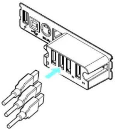
Connecting a Peripheral Device
-
Turn off the power.
-
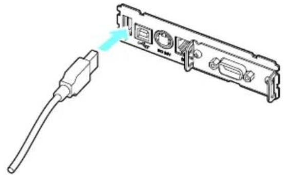
Connect the cable of a peripheral device to this port.
natural_image
Technical line drawing of an electronic device rear panel with connectors and a highlighted component (no text or symbols)Notes
A peripheral device cannot be controlled if it is connected to the USB power supply port. Be sure to connect it to the USB port of the interface board.
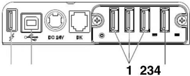
1: For peripheral device control
Connect a peripheral device.
The connected peripheral device can be controlled.
2: For Apple device connection
Connect with an Apple device.
The printer and Apple device will communicate via the Lightning cable.
Fast charging of the Apple device can also be carried out.
3: For host computer communication
Connect with a host computer.
The printer and host computer will communicate via USB.

Refer to 3.3 USB Interface
4: For supplying power
Connect a mobile device or other USB device.
Power can be supplied to a connected USB device.
* This port does not support USB data communication.
The Lightning model does not have a power supply function.

Refer to 3.8 USB Power Supply Port
Names of parts
natural_image
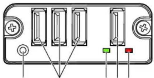
Diagram of a device rear panel with four vertical slots and terminal connectors (no text or symbols)1 2 34 5
1: Panel button
Control this interface board.
2: USB port for peripheral device connection (3 ports)
Connect a peripheral device.
3: USB port for Apple device connection (1 port)
Connect an Apple device.
Data can be transmitted even during fast charging of Apple devices.
4: Green LED
This LED indicates the communication status with the printer.
5: Red LED
This LED indicates the connection status with an Apple device.
Notes
■ Only connect peripheral devices specified by our company to the USB port.
■ Only plug in/remove peripheral devices when the printer power is turned off.
■ Operation of this board will start about 30 seconds after the power is turned on.
■ Use an MFi certified cable for connection with an Apple device.
Panel button operation
Use the panel button on the rear of the Lightning board to operate this board.
1: Print the interface board state
After starting the printer, pressing the panel button once prints the interface board state.
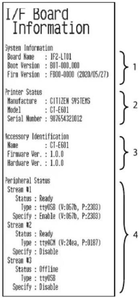
- System information of this interface board
- Information of the printer connected to this interface board
- Identification information of this interface board
- Peripheral device connection information
LED Functions
The tables below explain how to interpret LED indications.
1: Communication status with the printer
| Communicating LED (green) | |
| Not connected Unlit | |
| Connected Lit | |
| Communication in progress | Flashing |
2: Connection status with an Apple device
| Communicating LED (red) | |
| Not connected Unlit | |
| Connected Lit | |
| Communication failed Flashing(1-second cycle) | |
| Interface board error Flashing(0.2-second cycle) | |
3.8 USB Power Supply Port
Power (max. 2.1 A) can be supplied to a mobile device or other USB device by connecting the cable of the USB device to the power supply port.
Connecting Mobile Device or Other Device
- Turn off the power.
- Connect the cable of a mobile device or other device to the USB power supply port.
natural_image
Diagram of a USB cable connector with ports and an external cable, showing no text or symbols.Connecting a USB Device
The function assigned to each USB port differs.
Connect the USB device to be connected to the correct place in reference to the following figure.
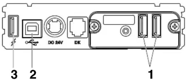
1: For peripheral device control
Connect a peripheral device.
The connected peripheral device can be controlled.
2: For host computer communication
Connect with a host computer.
The printer and host computer will communicate via USB.

Refer to 3.3 USB Interface
3: For supplying power
Connect a mobile device or other USB device.
Power can be supplied to a connected USB device.
* This port does not support USB data communication.

Refer to 3.8 USB Power Supply Port
Notes
■ This port does not support USB data communication.
■ Power may not be able to be supplied depending on the USB device to be used.
In this case, use the device's dedicated AC adapter or battery charger.
■ A USB cable for power supply is not included with this product.
Use a commercially available USB cable or the one that comes with the USB device.
■ The Lightning model does not have a power supply function.
3.9 Connecting the Cash Drawer
- Turn off the power.
- Confirm the orientation of the cash drawer kick-out cable connector and connect it to the cash drawer kick-out connector at the back of the printer.
- Remove the screw for the ground wire.
- Screw the cash drawer's ground wire to the body of the printer.
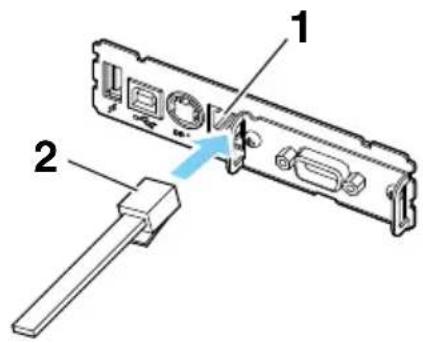
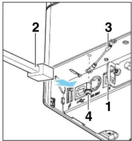
- Cash drawer kick-out connector
- Cash drawer kick-out cable connector
- Ground wire
- Screw for ground wire

CAUTION
■ Connect only the cash drawer kick-out cable to this connector. (Do not connect a telephone line.)
■ Hold the connector of the drawer kick cable perpendicular and straight when connecting or disconnecting it. Doing it at an angle may cause the connector to misconnect.
Notes
Signals cannot be output from the cash drawer kick-out connector while printing.
(1) Connector pin configuration
| No. Signal Function | 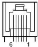 | |
| 1 FG Frame ground | ||
| 2 DRA WER1 Cash drawer | 1 drive signal | |
| 3 DRSW Cash drawer switch input | ||
| 4 VDR Cash drawer drive power supply | ||
| 5 DRA WER2 Cash drawer | 2 drive signal | |
| 6 GND Signal ground (common ground on circuits) | ||
* Applicable connector: RJ-11
(2) Electric characteristics
1) Drive voltage: 24 VDC
2) Drive current: Approx. 1 A max. (not to exceed 510 ms.)
3) DRSW signal: Signal levels: "L" = 0 to 0.5 V, "H" = 3 to 5 V
(3) DRSW signal
Status can be tested by commands.
(4) Drive circuit
Cash drawer kick-out connector
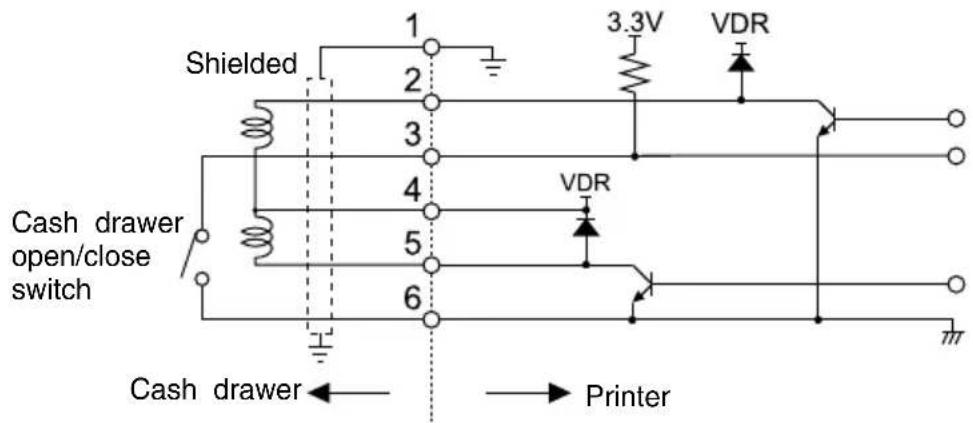

CAUTION
■ Cash drawers 1 and 2 cannot be operated at the same time.
■ The solenoid used for the cash drawer should be 24 Ω or more. Do not allow the electric current to exceed 1 A. Excessive current could damage or burn out the circuits.
3.10 Precautions for Installing the Printer
This product can be used horizontally or wall-mounted. Cannot be used vertically.
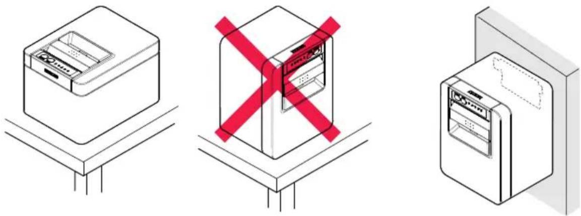
Horizontal position Vertical position Wall-mounted

CAUTION
Do not use the printer under the following conditions.
● Avoid locations subject to vibration or instability.
- Locations that are very dirty or dusty.
- Avoid locations where the printer is not level.
◆ The printer may fall and cause an injury.
◆ The quality of printing may deteriorate.
- Oriented other than as specified.
◆ Malfunction, failure, or electric shock may result.
Precautions for horizontal installations
- Do not use the full cut setting. Doing so could cause a cutter jam.
Precautions for wall installations
- Adjust the paper near-end sensor.
For wall mounting
If the printer is to be wall-mounted, ask a service person to install it.
For more information, please refer to the separate Wall Mount Kit manual.
3.11 Adjusting the Paper Near-end Sensor
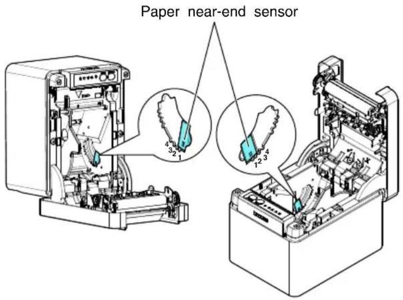
Change the settings of the paper near-end sensor to set the position at which the near-end of the paper is detected.
-
Gently press the paper near-end sensor with your finger.
-
Keep the paper near-end sensor pressed as you move it left and right. The sensor positions are shown below for the various diameters of the paper roll used.
(Unit: mm)
| Sensor position Paper roll outer diameter when near-end is detected | Exterior/ interior diameter of core of paper roll used |
| 1* Approximately ø22.0 ø18/ø12 | |
| 2 Approximately ø25.0 ø18/ø12 | |
| 3 Approximately ø29.0 ø18/ø12 | |
| 4 Approximately ø34.0 ø18/ø12 |
Notes:
* Sensor position when shipped from the factory. However, factory settings differ depending on the destination market.
Notes
The diameter of the roll of paper that is detected is an estimate. Some variations may occur depending on the paper.
3.12 Loading Paper
- Turn on the power.
- Pull the cover open lever toward you to open the paper cover.
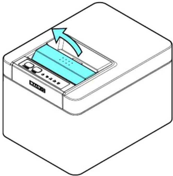
natural_image
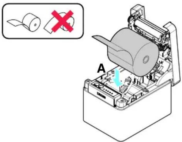
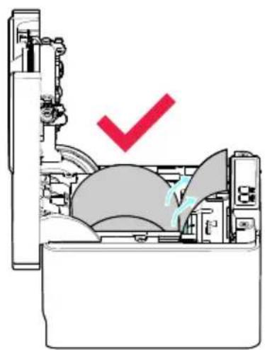
Illustration of a printer with a blue cover and arrow indicating motion (no text or symbols)- Load the paper roll so that the printable side of the paper is facing up, as shown by arrow A.
Set the roll paper so that it passes over the paper anti-curling damper.
natural_image
Diagram of a mechanical device with a red checkmark indicating a specific component (no text or symbols present)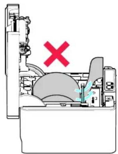
natural_image
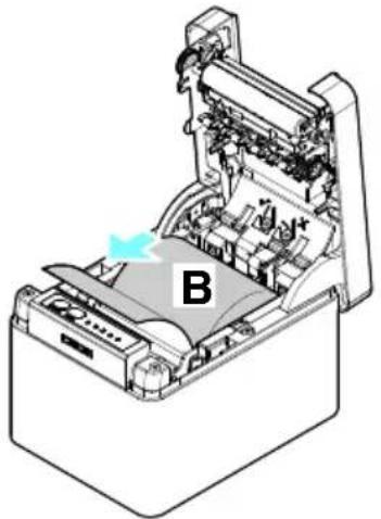
Cross-sectional diagram of a mechanical device with no visible text or symbols- Pull a few centimeters of paper straight out in the direction of arrow B.
natural_image
Isometric technical diagram of a printer or printer with internal components and a labeled section B (no text or symbols beyond label)- Close the paper cover until you hear a click. Paper is fed and cut automatically (by the factory setting).

CAUTION
■ When opening the paper cover, be careful not to touch the entrance of the blade of the auto cutter.
■ The print head is very hot immediately after printing. Be careful not to touch it with your hands.
■ Do not touch the print head with bare hands or metal objects.
■ When closing the paper cover, be careful not to pinch your fingers.
■ Be careful of paper cuts while loading the paper.
Notes
■ Always use the specified types of paper rolls.
■ Confirm that the paper roll is set correctly.
If the paper is skewed and not coming straight out of the paper cover, open it and straighten the paper.
■ Always pull a few centimeters of paper straight out of the printer if you open the paper cover while paper is loaded.
■ Press on the center of the paper cover to close it securely.
If only one of them is closed, uneven printing may occur.

Refer to PRECAUTIONS IN HANDLING THE PRINTER
3.13 58-mm Width Roll Paper Partition
- Turn off the power.
- Pull the cover open lever toward you to open the paper cover.
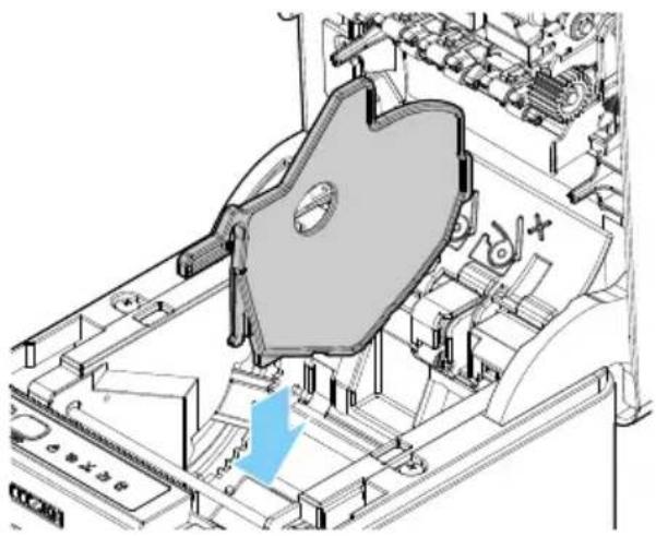
- Mount the supplied partition to the groove. When using the 80-mm width roll paper, remove the partition.
- Change the print area width while referring to "Manual Setting of Memory Switches" in Section 5.3.

Refer to 5.3 Manual Setting of Memory Switches
natural_image
Technical line drawing of a mechanical assembly with no visible text or symbols
CAUTION
■ When opening the paper cover, be careful not to touch the entrance of the blade of the auto cutter.
■ The print head is very hot immediately after printing. Be careful not to touch it with your hands.
■ Do not touch the print head with bare hands or metal objects.
Notes
■ When using 58-mm width media, be sure to mount the partition.
■ When using 58-mm wide paper, use the printer as a dedicated printer for that paper size.
The printer may not correctly feed paper or print if it is switched to 80-mm wide paper after using 58-mm wide paper.

Refer to PRECAUTIONS IN HANDLING THE PRINTER
3.14 Mounting the Cable Cover
- Align the claws of the cable cover with the grooves in the printer main unit and then insert them.
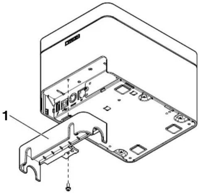
- Cable cover
3.15 Precautions for Creating Applications and Practical Operations
If printing is done immediately after the paper is partially cut and torn off, the top of the next print out may be distorted.
For printing after cutting, we recommend to print with the first line empty.
If you are using a serial interface that has a slow data transmission speed, streaks may appear in the printouts when you are printing graphics or gradated text, which require large amounts of data.
USB interfaces may be susceptible to the effects of electromagnetic interference from the host or environment.
If this is the case, try using a cable with ferrite cores on both ends, which are very effective at eliminating EMI.
3.16 Download Site for Various Electronic Files
You can view support information and download the latest documents, drivers, utilities, etc. from the following site.
https://www.citizen-systems.co.jp/en/printer/download/
4. MAINTENANCE AND TROUBLE-SHOOTING
4.1 Periodic Cleaning
How to care for the printer's exterior surface
After turning off the printer, wear gloves and use a soft cloth or an absorbent cotton to wipe it off.
At this time, be sure to unplug the AC power cord from the outlet.

CAUTION
■ Prolonged use of cleaning agents may cause whitening of the outer case.
■ When cleaning with an approved chemicals, test it beforehand and always refer the manufacturer's recommended procedure.
■ Do not clean with Ethanol where fire is present, as Ethanol is extremely flammable.
- Utilize a soft cloth when spreading chemicals onto printer. Do not spray or pour directly onto printer.
■ Wipe off the disinfectant with a soft damp cloth after cleaning procedure. No water droplets should remain on the printer.
■ Do not soak or wipe the inside of the printer nor allow disinfectant gets inside. It may cause a product failure.
How to clean the print head and platen
If the print head, platen, or other parts of the printer are dirty, the printer may not print cleanly or it could cause a malfunction. It is recommended that you clean the unit periodically (approximately two to three months) using the following procedure.
- Turn off the power.
At this time, be sure to unplug the AC power cord from the outlet.
-
Pull the cover open lever toward you to open the paper cover.
-
Wait a few minutes until the print head cools.
-
Use a cotton swab dampened with ethyl alcohol to wipe off any dirt and dust that is on the print head and platen.
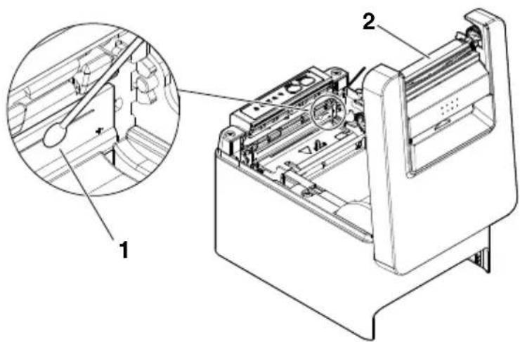
-
Print head
-
Platen

CAUTION
■ When opening the paper cover, be careful not to touch the entrance of the blade of the auto cutter.
■ The print head is very hot immediately after printing. Be careful not to touch it with your hands.
■ Do not touch the print head with bare hands or metal objects.

Refer to PRECAUTIONS IN HANDLING THE PRINTER
4.2 Clearing a Cutter Error
If the auto cutter stops during the auto cutter operation with the blade of the auto cutter in the open position due to foreign matter entering, paper jamming, etc., the CUTTER LED flashes. When a cutter error occurs, resolve the cutter error with the following procedure.
- Turn on the power.
- Pull the cover open lever toward you to open the paper cover.
- Remove any jammed paper including any scraps of paper. (Remove the paper roll that is loaded in the holder also.)
- Reload the paper roll and close the paper cover.

CAUTION
- When opening the paper cover, be careful not to touch the entrance of the blade of the auto cutter.
■ The print head is very hot immediately after printing. Be careful not to touch it with your hands.
■ Do not touch the print head with bare hands or metal objects.

Refer to PRECAUTIONS IN HANDLING THE PRINTER
4.3 Canceling print stop caused by a paper jam
The paper jamming sensor detects a paper jam at the paper exit and stops printing. Use the following method to release a print stop caused by a paper jam.
- Remove any paper that is jammed in the paper exit.
- If it cannot be removed, open the paper cover and remove the paper.
- Load paper, close the paper cover, and make sure that the PAPER LED is off.
4.4 Self Test
You can use self test to check for printer problems.
Performing a self test operation
- While paper is loaded, press and hold the FEED button and turn on the power.
- Hold the FEED button down for about one second until the buzzer sounds. Release the button to start self test. The printer will print its model name, version, memory switch settings, and built-in fonts.
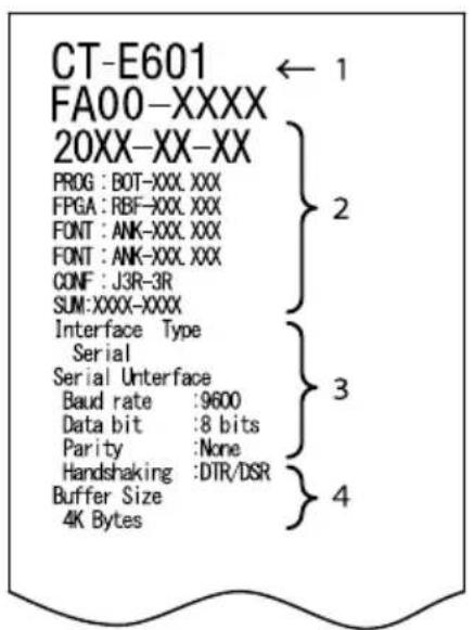
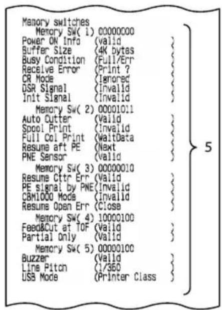
1: Printer type name
2: Firmware version
3: Interface settings
4: Buffer size
5: Memory switch settings
4.5 Hexadecimal Dump Printing
Print received data in hexadecimal. If problems such as missing or duplicated data occur, this function allows you to check whether or not the printer is receiving data correctly.
How to do hexadecimal dump printing
- Load paper.
- While the paper cover is open, hold down the FEED button as you turn on printing power. Keep FEED button pressing until the POWER LED starts to flash, and then close the paper cover.
- The printer will print "HEX dump print mode" followed by the received data printed in hexadecimal numbers and some characters.
How to stop hexadecimal dump printing
Do one of the following to stop printing.
- Press the FEED button consecutively three times
- Turn off the power
● Receive a reset command from an interface
Notes
■ The printer prints “.” if there is no character corresponding to the data.
■ None of the commands function during hexadecimal dump printing.
If print data does not cover a complete line, press the FEED button to advance the paper.
Print example
HEX dump print mode
61 62 63 64 65 66 67 0A 0D 0D 0D 0D abcdefg.....
4.6 Error Indications
● Paper end, paper near-end
The end of the roll of paper is detected at two stages, paper near-end and paperend. When paper near-end is detected, the PAPER LED flashes. Prepare a new paper roll. When paper end is detected, the PAPER LED lights and the buzzer sounds. Load a new paper roll. Memory switch settings can be used to disable the buzzer.
- Cover Open
If the cover is opened, the COVER LED lights and a buzzer sounds. The buzzer may not sound depending on the memory switch setting. Do not open the cover during printing. If the cover is accidentally opened, the COVER LEDflashes. Check the paper, pull it straight out of the printer by a couple of centimeters, and then close the cover. Printing restarts. A command must be sent to restart printing depending on the memory switch setting.
- Cutter error
If the auto cutter cannot move because of a paper jam or something else, the CUTTER LED flashes and the buzzer sounds. Remove the cause of the trouble and press the FEED button. If the auto cutter still does not move and the paper cover cannot be opened, refer to “Clearing a Cutter Error.”

Refer to 4.2 Clearing a Cutter Error
● Print stop due to paper jam
When a paper jam occurs at the paper exit, the PAPER LED blinks and printing stops.
Remove the jammed paper and load the paper.

Refer to 4.3 Canceling print stop caused by a paper jam
- Print head hot
When you print dense characters, dark images, or for an extended time in a hot environment, the print head temperature increases. If the print head exceeds a specified temperature, the printer stops printing and waits for the print head to cool. When this happens, the PAPER LED, CUTTER LED, and COVER LED flash. Printing resumes automatically when the print head cools.
The status display for various messages is shown below.
| Status | POWER LED | PAPER LED CUTTERLED | COVER LED SERVICELED | Buzzer*1 |
| Paper near-end | Lit Unlit Unlit No |
| Status POWER LED PAPER LED CUTTER | LED | COVER LED SERVICE LED | Buzzer*1 | |||
| Paper-end Lit Lit Unlit Unlit Unlit Yes*2 | ||||||
| Cover open*3 Lit Unlit Unlit Lit Unlit Yes*2 | ||||||
| Cover open II*4 | Lit Unlit Unlit Unlit Yes*2 |  | ||||
| Cutter locked Lit Unlit Unlit Unlit Yes |  | |||||
| Print stop due to paper jam | Lit Unlit Unlit Unlit No | |||||
| Low-voltage error | Lit |  |  |  | Unlit No | |
| High-voltage error | Lit Unlit Unlit Unlit | No |  | |||
| System error | Lit Unlit Unlit Unlit | No |  | |||
| Memory error | Unlit Unlit Unlit Unlit | No | 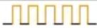 | |||
| Print head hot | Lit | Unlit No | ||||
| Wait for Macro Execution | Unlit Unlit | Unlit Unlit No | ||||
| Data reception | Unlit Unlit | Unlit Unlit No | ||||
Notes:
*1 Buzzer sounds when MSW5-1 (buzzer setting) is set to ON.
*2 MSW10-5 (buzzer event) can be configured to disable the buzzer.
*3 Indicated when a cover is opened during standby.
*4 Indicated when a cover is opened during printing.
4.7 Paper Jams
Take care to avoid obstruction of the paper outlet and paper jamming around the outlet during printing.
If paper cannot get out of the printer, it can roll up on the platen inside the printer and cause an error.
If the paper wraps around the platen, open the paper cover and carefully pull the paper out.
4.8 Precautions for Performing Printing for Which Printing Speed Changes
When printing for which the printing speed changes is performed, white lines may be printed or paper may not be fed depending on the printing conditions. To prevent these problems, change the following memory switch settings.
- Enable MSW2-3 (buffering).
- Increase the baud rate of MSW7-1 (serial baud rate).
- Change MSW10-2 (print speed) to a lower level.
Notes
Depending on the serial interface transmission speed, ambient temperature, print data duty, and other factors, changing the above settings may not eliminate the problems.
5.1 External Views and Dimensions
(Unit: mm)
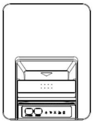
natural_image
Line drawing of a multi-tiered storage unit with control panel (no text or symbols)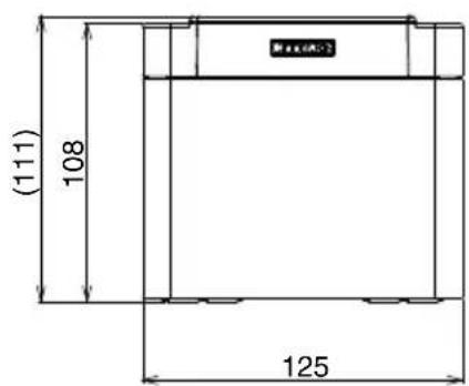
natural_image
Simple line drawing of a rectangular frame with a horizontal line and corner markers, labeled '165' at the bottom (no text or symbols within the diagram itself)5.2 Printing Paper
Use the paper shown in the following table or paper of the same quality.
| Paper type Product name | |
| Recommended thermal roll paper | Nippon Paper TP50KR-2Y, TP50KJ-R, TL69KS-LH, TF50KS-E2DOji Paper PD150R, PD160R, PD160R-63Mitsubishi Paper Mills HP220AB-1, P220ABKoehler KT48-FA |
(Unit: mm)
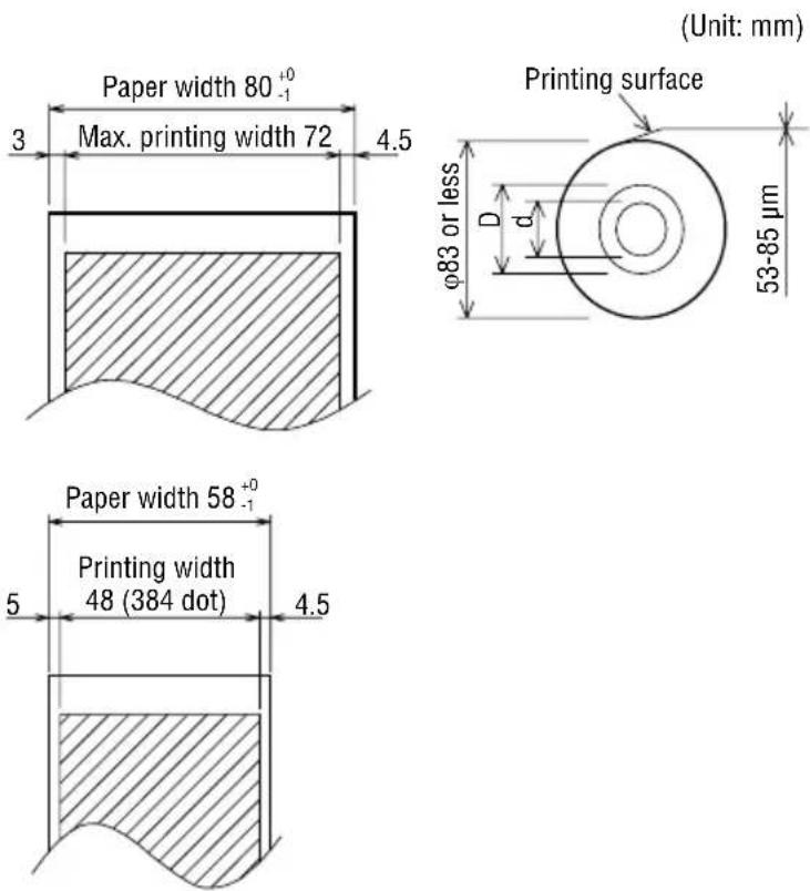
| Paper thickness (μm) 53 to 85 | |
| Core inner diameter d (mm) ø12 | |
| Core outer diameter D (mm) ø18 |
Notes
Use thermal paper that is wound as follows:
● Not creased and fits tight to the core.
- Not folded.
● Not glued to the core.
- Rolled with the printable side out.
5.3 Manual Setting of Memory Switches
Memory switches are used to set various printer settings. Memory switches can be set manually, or by utilities or commands. This section explains how to perform manual settings.
For information on how to set the memory switches using commands, please refer to the Command Reference.
Quick setting mode
The settings for the memory switches for a replacement printer's manufacturer, model, paper width, and character spacing can be set at the same time to the optimum settings.
Do the settings while confirming the selected items on the printout.
- Load paper.
- While the paper cover is open, press and hold the FEED button and turn on the power.
- Press the FEED button three and close the paper cover.
The printer enters memory switch quick setting mode.
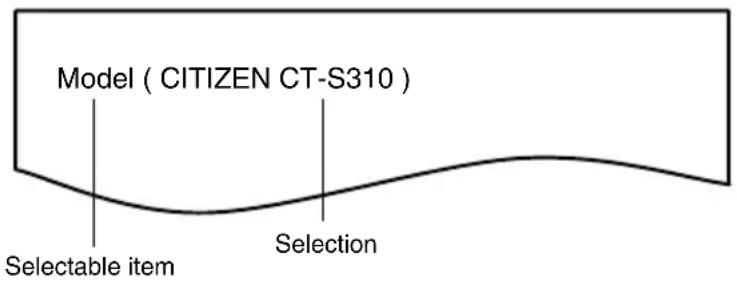
The selectable item "Model" and the selection are printed.
- Press the FEED button.
A selection is printed in order through the cycle each time the FEED button is pressed.
Press the FEED button until the selection you want is printed.
- Press the FEED button for at least two seconds.
The selection is set.
If there is another selectable item, it and the selection are printed.
- Repeat steps 4 and 5 to select and set the printer's model, paper width, character spacing (EPSON T88 only).
When all the items are set, "Save To Memory" is printed.
7. Press the FEED button for at least two seconds.
The changed memory switch settings are saved and a list of them is printed.
The printer exits quick setting mode when printing is finished.
Selected item Automatic memory switch settings
| Manufacturer | Paper width | Character space |
| CITIZEN CT-S310 | 58 mm | WaitData Invalid 384 dots - |
| 80 mm | WaitData Invalid 576 dots - | |
| EPSON T88 | 58 mm | 0 dot WaitData Invalid 360 dots 0 dot |
| 1 dot WaitData Invalid 390 dots 1 dot | ||
| 80 mm | 0 dot WaitData Invalid 512 dots 0 dot | |
| 1 dot WaitData Invalid 546 dots 1 dot | ||
| EPSON 203dpi | 80 mm | WaitData Invalid 576 dots 0 dot |
| 58 mm | WaitData Invalid 420 dots - |
Individual setting mode
Set the memory switches individually.
Do the settings while confirming the memory switch function and settings on the print-out.
- Load paper.
- While the paper cover is open, press and hold the FEED button and turn on the power.
- Press the FEED button twice and close the paper cover.
The printer enters the mode for setting memory switches individually.
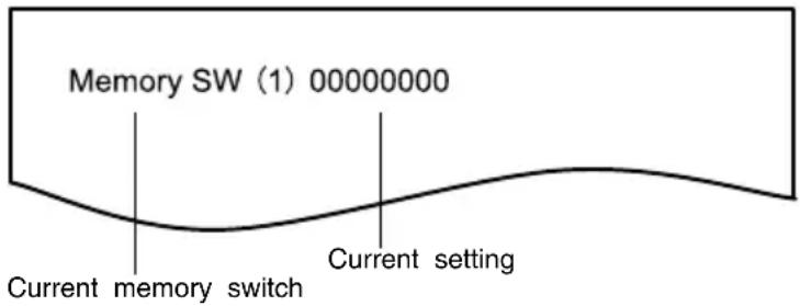
The printer prints "Memory SW (1)" and the current setting, 0 (off) or 1 (on).
(The current settings for memory switches 7 to 13 are not printed.)
- Press the FEED button.
Each press of the FEED button cycles through the list of memory switches in the following sequence: "Memory SW (1)" > "Memory SW (2)" > ... "Memory SW (11)" or "Memory SW (13)" > "Save To Memory" > "Memory SW (1)".
Press the FEED button until the number for the memory switch you want to change is printed.
- Press the FEED button for at least two seconds.
A setting for the memory switch is printed, through the cycle, each time the FEED button is pressed for at least two seconds.
Press the FEED button for at least two seconds to cycle through the list until the function of the memory switch you want to change is printed.
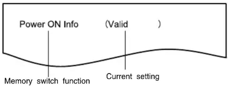
6. Press the FEED button.
A setting is printed each time the FEED button is pressed in order through the cycle.
When the current settings are printed, the COVER LED lights.
Press the FEED button until the setting you want is printed.
7. Press the FEED button for at least two seconds.
The selected settings are set.
The next memory switch function and settings are printed.
- Repeat steps 5 to 7 to change different functions for the current memory switch number.
- Open the paper cover and close it.
The changed memory switch settings are printed.
- Repeat steps 4 to 9 to change functions for a different memory switch number.
- Press the FEED button until "Save To Memory" is printed.
- Press the FEED button for at least two seconds.
The changed memory switch settings are saved and a list of them is printed.
The printer exits individual setting mode when printing is finished.
Memory switch initialization
Set all the memory switches to the factory settings.
- Do steps 1 through 3 of the procedure to enter individual setting mode.
- Press the FEED button until "Save To Memory" is printed.
-
Open the paper cover.
-
Press the FEED button for at least two seconds.
All memory switches change to the factory settings.
5. Close the paper cover.
The function of each memory switch is shown in the following table. (Shaded values are factory settings.)
| Switch no. | Function OFF ON | ||
| MSW1-1 Power ON Info Valid Not Send | |||
| MSW1-2 Buffer Size 4K bytes 45 bytes | |||
| MSW1-3 Busy Condition Full/Err Full | |||
| MSW1-4 Receive Error Print“?” No Print | |||
| MSW1-5 | CR Mode Ignored | LF | |
| Switch no. Function OFF ON | |||
| MSW1-6 Reserved Fixed — | |||
| MSW1-7 DSR Signal Invalid Valid | |||
| MSW1-8 INIT Signal Invalid Valid | |||
| MSW2-1 Reserved — Fixed | |||
| MSW2-2 Auto Cutter Invalid Valid | |||
| MSW2-3 Spool Print Invalid Valid | |||
| MSW2-4 | Full Col Print | LineFeed WaitData | |
| MSW2-5 | Resume aft PE | Next | Top |
| MSW2-6 Reserved Fixed — | |||
| MSW2-7 Reserved Fixed — | |||
| MSW2-8 | PNE Sensor | Valid Invalid | |
| MSW3-1 | Resume Ctr Err | Valid Invalid | |
| MSW3-2 | PE signal by PNE | Valid Invalid | |
| MSW3-3 Reserved Fixed — | |||
| MSW3-4 Reserved Fixed — | |||
| MSW3-5 Reserved Fixed — | |||
| MSW3-6 Reserved Fixed — | |||
| MSW3-7 | CBM1000 Mode | Invalid Valid | |
| MSW3-8 | Resume Open Err | Close | Command |
| MSW4-1 Reserved Fixed — | |||
| MSW4-2 Reserved Fixed — | |||
| MSW4-3 | Feed&Cut at TOF | Invalid | Valid |
| MSW4-4 Reserved Fixed — | |||
| MSW4-5 Reserved Fixed — | |||
| MSW4-6 Reserved Fixed — | |||
| MSW4-7 Reserved Fixed — | |||
| MSW4-8 Partial Only Invalid | Valid | ||
| MSW5-1 | Buzzer Valid | Invalid | |
| MSW5-2 | Line Pitch | 1/360 | 1/406 |
| MSW5-3 USB Mode Virtual COM Printer Class | |||
| MSW5-4 Reserved Fixed — | |||
| MSW5-5 Reserved Fixed — | |||
| MSW5-6 Reserved Fixed — | |||
| MSW5-7 Reserved Fixed — | |||
| MSW5-8 Reserved Fixed — | |||
| MSW6-1 | Act. For Driver Invalid | Valid | |
| MSW6-2 | Character Space | Invalid Valid | |
| MSW6-3 | USB Power Save | Invalid Valid | |
| MSW6-4 Reserved Fixed — | |||
| MSW6-5 Reserved Fixed — | |||
| MSW6-6 Reserved Fixed — | |||
| MSW6-7 | USB Power@PW-OFF | Invalid Valid | |
| MSW6-8 | Power ON trigger | Power switch ON | AC power input |
| Switch no. | Function Initial setting | Setting value | |
| MSW7-1 | Baud Rate 9600 bps 1200 | bps, 2400 bps, 4800 bps, 9600 bps, 19200 bps, 38400 bps, 57600 bps, 115200 bps | |
| MSW7-2 | Data Length 8bits 7bits, 8bits | ||
| MSW7-3 | Stop Bit 1bit 1bit, 2bits | ||
| MSW7-4 | Parity NONE NONE, ODD, EVEN | ||
| MSW7-5 | Flow Control DTR/DSR DTR/DSR, XON/XOFF | ||
| MSW7-6 | DMA Control | Valid Valid | Invalid |
| MSW7-7 | VCom Protocol | PC Setting | PC Setting, DTR/DSR, XON/XOFF |
| MSW8-1 | Print Width 576 dots | 576 dots, 546 dots, 512 dots, 420 dots, 390 dots, 384 dots, 360 dots | |
| MSW8-3 | Top Margin | 12 mm | 2 mm, 3 mm, 4 mm, 5 mm, 6 mm, 7 mm, 8 mm, 9 mm, 10 mm, 11 mm, 12 mm |
| MSW8-4 | Line Gap Reduce | Invalid | Invalid, 3/4, 2/3, 1/2, 1/3, 1/4, 1/5, ALL |
| MSW8-5 | Reduced Char V/H | 100% / 100% | 100% / 100%, 75% / 100%, 50% / 100%, 100% / 75%, 75% / 75%, 50% / 75% |
| MSW8-6 | Auto Side Shift Invalid Invalid, 1 dot | 2 dots, 3 dots, 4 dots, 5 dots, 6 dots, 7 dots | |
| MSW9-1 | Code Page | PC437 | PC 437, Katakana, PC 850, PC 858, PC 860, PC 863, PC 865, PC 852, PC 866, PC 857, WPC1252, Space page, PC 864, ThaiCode11 1Pass, ThaiCode11 3Pass, ThaiCode18 1Pass, ThaiCode18 3Pass, TCVN-3, WPC1258 |
| MSW9-2 | Int'Char Set | U.S.A | USA, France, Germany, England, Denmark, Sweden, Italy, Spain, Japan, Norway, Denmark 2, Spain 2, Latin America, Korea, Croatia, China, Vietnam |
| MSW9-4 | Kanji code Invalid Disabled, JIS (Japan), SJIS: CP932 (Japan), SJIS: X0213 (Japan), GB18030 (China), KS Hangul (South Korea), EUC Hangul (South Korea), BIG5-HKSCS | ||
| MSW10-1 | Print Density | 100 % | 70 %, 75 %, 80 %, 85 %, 90 %, 95 %, 100 %, 105 %, 110 %, 115 %, 120 %, 125 %, 130 %, 135 %, 140 % |
| MSW10-2 | Print Speed | Level 9 | Level 1, Level 2, Level 3, Level 4, Level 5, Level 6, Level 7, Level 8, Level 9 |
| MSW10-4 | Old Command Invalid Invalid, CBM1, CBM2 | ||
| MSW10-5 | Buzzer Event Not By C.Open | All Event/Error, Not by C.Open, Not by C.Open/PE | |
| MSW10-6 | Buzzer Sound | Tone 2 | Tone 1, Tone 2, Tone 3, Tone 4 |
| MSW13-1 | Security/Target | Low/All | Low/All, Mid/All, Mid/Paired only, Hi/All, Hi/Paired only |
| MSW13-5 BT | Device Scan Discoverable No Response, Discoverable | ||
| MSW13-6 Auto Reconnect Valid Valid Invalid, Valid | |||
FRANÇAIS
PRÉCAUTIONS GÉNÉRALES
- Apple, Apple TV, Apple Watch, iPad, iPad Air, iPad Pro, iPhone, and Lightning are trademarks of Apple Inc., registered in the U.S. and other countries. tvOS is a trade-
mark of Apple Inc. The trademark "iPhone" is used in Japan with a license from Aiphone K.K.
natural_image
Technical line drawing of a mechanical device with an arrow pointing to a component, no text or symbols present.natural_image
Technical line drawing of a device internal structure showing connector and housing (no text or symbols)natural_image
Diagram of an electronic component with two connectors and a blue arrow indicating direction (no text or symbols)Remarques
natural_image
Diagram of an electronic device showing a connector with ports and a cable inserted (no text or symbols)natural_image
Technical diagram of an electronic device showing a connector with two pins and a blue arrow indicating direction (no text or symbols present)Remarques
natural_image
Diagram of an electronic device showing internal components and a connector (no text or symbols)Remarques
natural_image
Diagram of a device casing with ports and indicator lights (no text or symbols)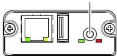
natural_image
Diagram of a device rear panel with ports and indicator lights (no text or labels)LAN sans filEthernet
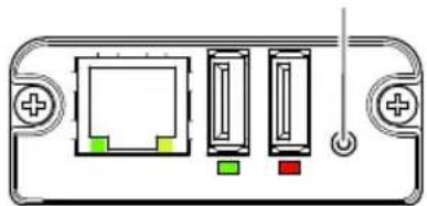
natural_image
Diagram of a device rear panel with ports and internal components (no text or symbols)natural_image
Diagram of a device rear panel with ports and indicator lights (no text or symbols)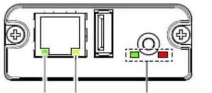
natural_image
Diagram of a device rear panel with ports and indicator lights (no text or symbols)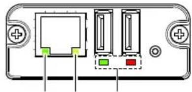
natural_image
Diagram of a device rear panel with ports and connectors (no text or symbols)Copyright © 2012 CITIZEN SYSTEMS JAPAN CO.,LTD. All rights reserved.
natural_image
Technical line drawing of an electronic device rear panel with a connector inserted (no text or symbols)natural_image
Technical line drawing of an electronic component with connectors and a highlighted section (no text or symbols)Remarques
natural_image
Diagram of a device rear panel with four vertical slots and terminal connectors (no text or symbols)1 2 34 5
natural_image
Diagram of a USB cable connector with ports and an arrow indicating a specific port (no text or symbols present)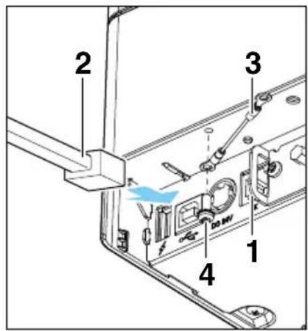
natural_image
Illustration of a printer with a blue cover and arrow indicating compression or disassembly (no text or symbols)natural_image
Diagram of a mechanical device with a red checkmark indicating a specific component (no text or symbols present)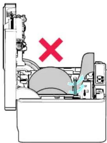
natural_image
Diagram of a mechanical device with a red X mark indicating a failure or rejection (no text or symbols present)natural_image
Isometric technical diagram of a printer internal structure with labeled component B (no text or symbols beyond label)natural_image
Technical line drawing of a mechanical assembly with no visible text or symbols
ATTENTION
- Cache du câble
https://www.citizen-systems.co.jp/en/printer/download/
natural_image
Line drawing of a multi-tiered storage unit with control panel (no text or symbols)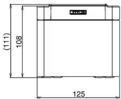
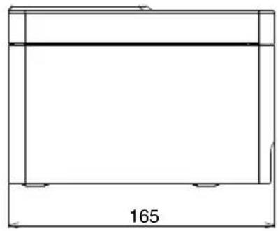
natural_image
Simple line drawing of a rectangular frame with a horizontal line and corner markers, labeled '165' at the bottom (no text or symbols within the diagram itself)natural_image
Technical line drawing of a mechanical device with warning symbol (no text or labels)natural_image
Technical line drawing of a device rear panel with connector ports and internal components (no text or symbols)natural_image
Technical illustration of a mechanical component with two connectors and a blue directional arrow indicating motion (no text or symbols)Hinweise
natural_image
Diagram of an electronic device showing a connector with ports and a cable inserted (no text or symbols)natural_image
Technical line drawing of an electronic device showing a connector and two terminal ports (no text or symbols)Hinweise
natural_image
Diagram of an electronic device showing a connector with ports and a cable outlet (no text or labels)Hinweise
natural_image
Diagram of a device rear panel with ports and indicator lights (no text or symbols)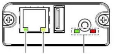
natural_image
Diagram of a device rear panel with ports and indicators (no text or symbols)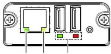
natural_image
Diagram of a device rear panel with ports and connectors (no text or symbols)1 2 3 1 2 31 2 3
WLANEthernet Ethernet/WLAN
USB-Host-Modell
Copyright © 2012 CITIZEN SYSTEMS JAPAN CO.,LTD. All rights reserved.
natural_image
Technical line drawing of an electronic device rear panel with a connector inserted (no text or symbols)natural_image
Technical line drawing of an electronic component with three connectors and a highlighted section (no text or symbols)Hinweise
natural_image
Diagram of a device rear panel with four vertical slots and terminal connectors (no text or symbols)1 2 34 5
1: Bedienfeldtaste
natural_image
Diagram of a USB cable connector with ports and cable ends, no text or symbols present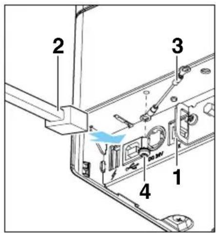
natural_image
Illustration of a printer with a blue cover and paper feed, showing airflow direction (no text or symbols)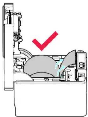
natural_image
Diagram of a mechanical device with a checkmark indicating a specific component (no text or symbols present)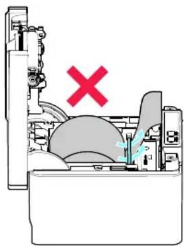
natural_image
Cross-sectional diagram of a mechanical device with no visible text or symbolsnatural_image
Isometric technical diagram of a printer or printer with internal components and a labeled section B (no text or symbols beyond label)natural_image
Technical line drawing of a mechanical assembly with no visible text or symbols
VORSICHT
natural_image
Technical line drawing of a device rear panel with internal components and a labeled component (no text or symbols present)- Kabelabdeckung
https://www.citizen-systems.co.jp/en/printer/download/
natural_image
Line drawing of a refrigerator with front panel and side control buttons (no text or symbols)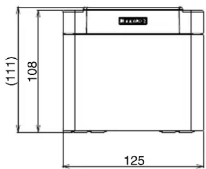
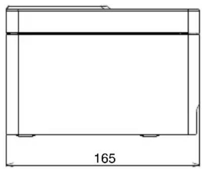
natural_image
Pure technical drawing of a rectangular frame with dimension label 165 (no text or symbols beyond the number)5.2 Druckpapier
- Apple, Apple TV, Apple Watch, iPad, iPad Air, iPad Pro, iPhone, and Lightning are trademarks of Apple Inc., registered in the U.S. and other countries. tvOS is a trademark of Apple Inc. The trademark "iPhone" is used in Japan with a license from Aiphone K.K.
natural_image
Technical line drawing of a mechanical device with a warning symbol (no text or labels present)natural_image
Technical line drawing of a device rear panel with connectors and a connector inserted into a housing (no text or symbols)natural_image
Technical illustration of a device housing with two connectors and internal components, showing no text or symbols.Note
natural_image
Diagram of an electronic device showing a connector with ports and a cable inserted (no text or symbols)natural_image
Technical diagram of an electronic device showing a connector with two pins and a blue arrow indicating direction (no text or symbols present)Note
natural_image
Diagram of an electronic device showing a connector with ports and a cable outlet (no text or labels)Note
Wireless LANModello host/Wi
natural_image
Diagram of a device casing with ports and indicator lights (no text or symbols)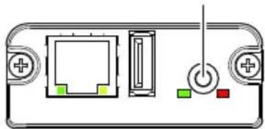
natural_image
Diagram of a device rear panel with ports and indicator lights (no text or symbols)Wireless LANEthernet
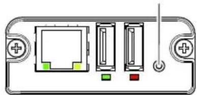
natural_image
Diagram of a device rear panel with ports and internal components (no text or labels)Modello host/Wireless LAN USB Ethernet
natural_image
Diagram of a device rear panel with ports and indicator lights (no text or symbols)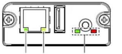
natural_image
Diagram of a device rear panel with ports and indicator lights (no text or symbols)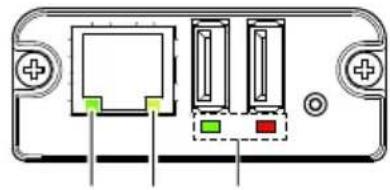
natural_image
Diagram of a device rear panel with ports and connectors (no text or symbols)1 2 3 1 2 31 2 3
Wireless LANEthernet Modello host/Wireless LAN
USB Ethernet
Copyright © 2012 CITIZEN SYSTEMS JAPAN CO.,LTD. All rights reserved.
natural_image
Technical line drawing of an electronic device rear panel with a connector inserted (no text or symbols)natural_image
Technical line drawing of an electronic component with three connectors and a highlighted section (no text or symbols)Note
natural_image
Diagram of a device rear panel with four vertical slots and terminal connectors (no text or symbols)1 2 34 5
1: Pulsante del pannello
natural_image
Diagram of a computer interface showing a cable inserted into a port with labeled ports (no text or symbols present)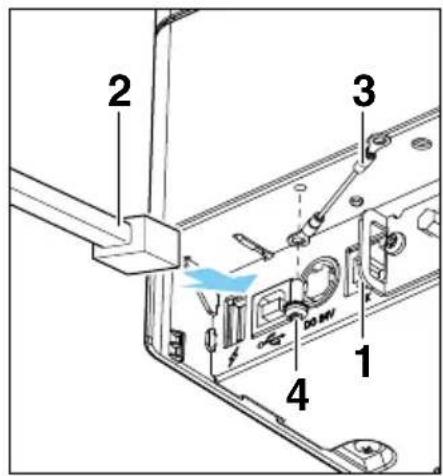
natural_image
Illustration of a printer with a blue cover and arrow indicating compression or disassembly (no text or symbols)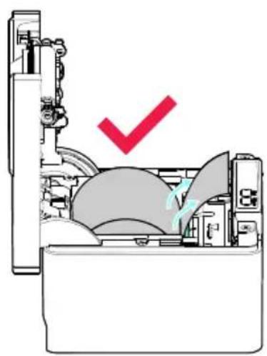
natural_image
Cross-sectional diagram of a mechanical device with a red checkmark indicating a specific component (no text or symbols present)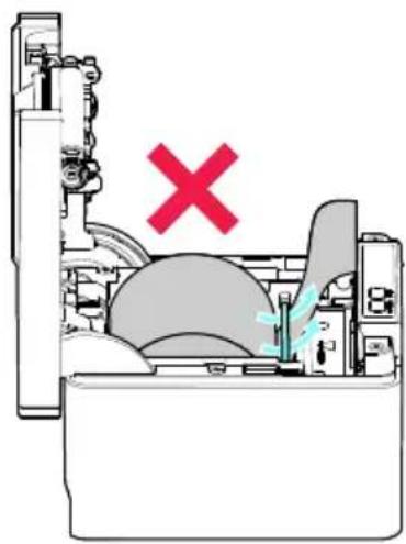
natural_image
Cross-sectional diagram of a mechanical device with no visible text or symbolsnatural_image
Technical line drawing of an open industrial machine with internal components and a labeled component 'B' (no text or symbols beyond label)natural_image
Technical line drawing of a mechanical assembly with no visible text or symbols
ATTENZIONE
natural_image
Technical line drawing of a device casing with internal components and a labeled part (1), showing no text or symbols beyond the number '1'- Coperchio del cavo
https://www.citizen-systems.co.jp/en/printer/download/
natural_image
Line drawing of a multi-tiered storage unit with control panel (no text or symbols)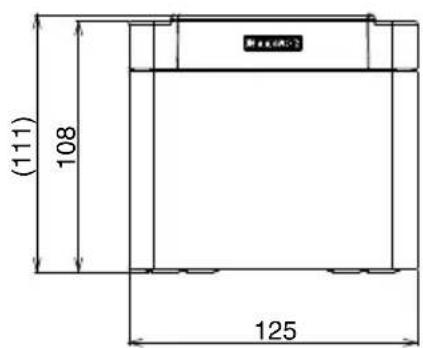
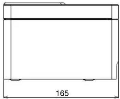
natural_image
Simple line drawing of a rectangular frame with a horizontal line and corner markers, labeled '165' at the bottom (no text or symbols within the diagram itself)| N. switch | Funzione OFF ON | ||
| MSW1-1 Power ON Info Valid Not Send | |||
| MSW1-2 Buffer Size 4K bytes 45 bytes | |||
| N. switch Funzione OFF ON | |||
| MSW1-3 Busy Condition Full/Err Full | |||
| MSW1-4 Receive Error Print“?” No Print | |||
| MSW1-5 Mode Ignored LF | |||
| MSW1-6 Reserved Fixed — | |||
| MSW1-7 DSR Signal | Invalid | Valid | |
| MSW1-8 INIT Signal | Invalid | Valid | |
| MSW2-1 Reserved | — | Fixed | |
| MSW2-2 | Auto Cutter | Invalid | Valid |
| MSW2-3 Spool Print | Invalid | Valid | |
| MSW2-4 | Full Col Print | LineFeed WaitData | |
| MSW2-5 | Resume aft PE | Next | Top |
| MSW2-6 Reserved Fixed — | |||
| MSW2-7 Reserved Fixed — | |||
| MSW2-8 | PNE Sensor | Valid | Invalid |
| MSW3-1 | Resume Ctr Err Valid | Invalid | |
| MSW3-2 | PE signal by PNE | Valid | Invalid |
| MSW3-3 Reserved Fixed — | |||
| MSW3-4 Reserved Fixed — | |||
| MSW3-5 Reserved Fixed — | |||
| MSW3-6 Reserved Fixed — | |||
| MSW3-7 | CBM1000 Mode | Invalid | Valid |
| MSW3-8 | Resume Open Err | Close | Command |
| MSW4-1 Reserved Fixed — | |||
| MSW4-2 Reserved Fixed — | |||
| MSW4-3 | Feed&Cut at TOF | Invalid | Valid |
| MSW4-4 Reserved Fixed — | |||
| MSW4-5 Reserved Fixed — | |||
| MSW4-6 Reserved Fixed — | |||
| MSW4-7 Reserved Fixed — | |||
| MSW4-8 Partial Only | Invalid | Valid | |
| MSW5-1 | Buzzer | Valid | Invalid |
| MSW5-2 | Line Pitch 1/360 | 1/406 | |
| MSW5-3 USB Mode Virtual COM Printer Class | |||
| MSW5-4 Reserved Fixed — | |||
| MSW5-5 Reserved Fixed — | |||
| MSW5-6 Reserved Fixed — | |||
| MSW5-7 Reserved Fixed — | |||
| MSW5-8 Reserved Fixed — | |||
| MSW6-1 | Act. For Driver | Invalid | Valid |
| MSW6-2 | Character Space | Invalid | Valid |
| MSW6-3 | USB Power Save | Invalid | Valid |
| MSW6-4 Reserved Fixed — | |||
| MSW6-5 Reserved Fixed — | |||
| MSW6-6 Reserved Fixed — | |||
| MSW6-7 | USB Power@PW-OFF | Invalid | Valid |
| MSW6-8 | Power ON trigger | Power switch ON | AC power input |
| N. switch Funzione Initial setting | Setting value | ||
| MSW7-1 Baud Rate 9600 bps 1200 bps, 2400 bps, 4800 bps, 9600 bps, 19200 bps, 38400 bps, 57600 bps, 115200 bps | |||
| MSW7-2 Data Length 8bits 7bits, 8bits | |||
| MSW7-3 Stop Bit 1bit 1bit, 2bits | |||
| MSW7-4 Parity NONE NONE, ODD, EVEN | |||
| MSW7-5 Flow Control DTR/DSR | DTR/DSR, XON/XOFF | ||
| MSW7-6 | DMA Control | Valid | Valid, Invalid |
| MSW7-7 | VCom Protocol | PC Setting | PC Setting, DTR/DSR, XON/XOFF |
| MSW8-1 Print Width 576 dots | 576 dots, 546 dots | 512 dots, 420 dots, 390 dots, 384 dots, 360 dots | |
| MSW8-3 | Top Margin | 12 mm | 2 mm, 3 mm, 4 mm, 5 mm, 6 mm, 7 mm, 8 mm, 9 mm, 10 mm, 11 mm, 12 mm |
| MSW8-4 | Line Gap Reduce | Invalid | Invalid, 3/4, 2/3, 1/2, 1/3, 1/4, 1/5, ALL |
| MSW8-5 | Reduced Char V/H | 100% / 100% | 100% / 100%, 75% / 100%, 50% / 100%, 100% / 75%, 75% / 75%, 50% / 75% |
| MSW8-6 | Auto Side Shift | Invalid | Invalid, 1 dot, 2 dots, 3 dots, 4 dots, 5 dots, 6 dots, 7 dots |
| MSW9-1 | Code Page | PC437 | PC 437, Katakana, PC 850, PC 858, PC 860, PC 863, PC 865, PC 852, PC 866, PC 857, WPC1252, Space page, PC 864, ThaiCode11 1Pass, ThaiCode11 3Pass, ThaiCode18 1Pass, ThaiCode18 3Pass, TCVN-3, WPC1258 |
| MSW9-2 | Int'Char Set | U.S.A | USA, France, Germany, England, Denmark, Sweden, Italy, Spain, Japan, Norway, Denmark 2, Spain 2, Latin America, Korea, Croatia, China, Vietnam |
| MSW9-4 Kanji code Invalid Disabled, JIS (Japan), SJIS: CP932 (Japan), SJIS: X0213 (Japan), GB18030 (China), KS Hangul (South Korea), EUC Hangul (South Korea), BIG5-HKSCS | |||
| MSW10-1 | Print Density | 100 % | 70 %, 75 %, 80 %, 85 %, 90 %, 95 %, 100 %, 105 %, 110 %, 115 %, 120 %, 125 %, 130 %, 135 %, 140 % |
| MSW10-2 | Print Speed | Level 9 | Level 1, Level 2, Level 3, Level 4, Level 5, Level 6, Level 7, Level 8, Level 9 |
| MSW10-4 | Old Command Invalid Invalid, CBM1, CBM2 | ||
| MSW10-5 Buzzer Event Not By C.Open | All Event/Error, Not by C.Open, Not by C.Open/PE | ||
| MSW10-6 | Buzzer Sound | Tone 2 | Tone 1, Tone 2, Tone 3, Tone 4 |
| MSW13-1 | Security/Target | Low/All | Low/All, Mid/All, Mid/Paired only, Hi/All, Hi/Paired only |
| MSW13-5 BT Device Scan Discoverable No Response, Discoverable | |||
| MSW13-6 Auto Reconnect Valid Invalid, Valid | |||
ESPAÑOL
PRECAUCIONES GENERALES
- Apple, Apple TV, Apple Watch, iPad, iPad Air, iPad Pro, iPhone, and Lightning are trademarks of Apple Inc., registered in the U.S. and other countries. tvOS is a trade-
mark of Apple Inc. The trademark "iPhone" is used in Japan with a license from Aiphone K.K.
natural_image
Technical line drawing of a mechanical device with warning symbol (no text or labels)natural_image
Technical line drawing of a device's internal components, showing connector and housing assembly (no text or symbols)natural_image
Diagram of a device component with two connectors and a blue arrow indicating direction (no text or symbols)Notas
natural_image
Diagram of an electronic device showing a cable connector inserted into a port with ports and connectors (no text or symbols visible)natural_image
Technical line drawing of an electronic device showing a connector with two pins and a blue directional arrow indicating motion (no text or symbols present)Notas
natural_image
Diagram of an electronic device showing a connector with ports and a cable outlet (no text or labels)Notas
LAN inalámbrica
natural_image
Diagram of a device rear panel with ports and indicator lights (no text or symbols)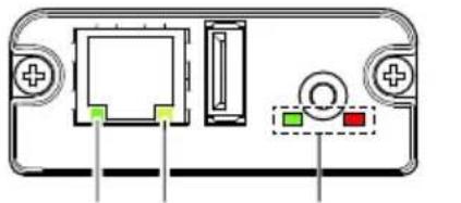
natural_image
Diagram of a device rear panel with ports and indicator lights (no text or symbols)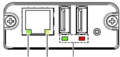
natural_image
Diagram of a device rear panel with ports and connectors (no text or symbols)1 2 3 1 2 31 2 3
LAN inalámbricaEthernet Ethernet/LAN inalámbrica
Modelo de host USB
Copyright © 2012 CITIZEN SYSTEMS JAPAN CO.,LTD. All rights reserved.
natural_image
Technical line drawing of an electronic device rear panel with a connector inserted (no text or symbols)natural_image
Technical line drawing of an electronic component with connectors and a highlighted section (no text or symbols)Notas
natural_image
Diagram of a device rear panel with four vertical slots and terminal connections (no text or labels)1 2 34 5
1: Botón del panel
natural_image
Diagram of a USB cable connector with ports and an external cable, showing no text or symbols.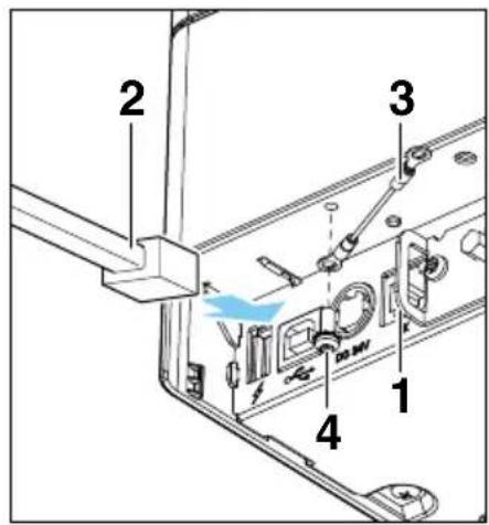
* Conector applicable: RJ-11
natural_image
Illustration of a printer with a blue cover and arrow indicating compression or disassembly (no text or symbols)natural_image
Cross-sectional diagram of a refrigerator interior with a red checkmark indicating a location (no text or symbols present)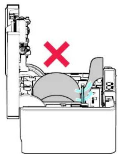
natural_image
Cross-sectional diagram of a mechanical device with no visible text or symbolsnatural_image
Isometric technical diagram of a mechanical device with labeled component B (no text or symbols beyond label)natural_image
Technical line drawing of a mechanical assembly with no visible text or symbols
PRECAUCIÓN
- Tapa de los cables
https://www.citizen-systems.co.jp/en/printer/download/
natural_image
Line drawing of a multi-tiered storage unit with control panel (no text or symbols)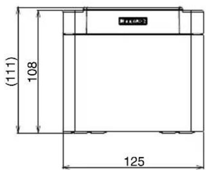
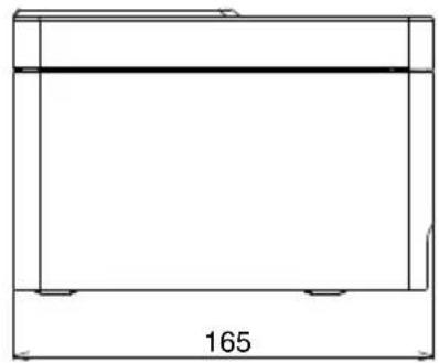
natural_image
Simple line drawing of a rectangular frame with a horizontal line and corner markers, labeled '165' at the bottom (no text or symbols within the diagram itself)Elizabeth House, 56-60 London Road
70329 Stuttgart
Staines-Upon-Thames, TW18 4HF
Germany
United Kingdom
Tel: +49 (0) 711 49032-0
Tel: +44 (0) 20 8893 1900
Fax:+49(0)71149032-45
Fax: +44 (0) 20 8893 0080
http://www.citizen-europe.com

- LINE THERMAL PRINTER
- Compliance Statement for European Users
- Sicherheitshinweis
- SAFETY PRECAUTIONS...WHICH SHOULD BE STRICTLY OB- SERVED
- WARNING
- CAUTION
- PRECAUTIONS ON PRINTER INSTALLATION
- ■ Do not use or store this product in a place where it will be exposed to:
- ■ These locations create the risk of printer damage, as well as product failure, overheating, emission of smoke, fire, or electric shock.
- ■ Do not handle the printer in the following ways:
- ■ These actions create the risk of printer damage, as well as product failure, overheating, emission of smoke, fire, or electric shock.
- Do not use the printer under the following conditions.
- PRECAUTIONS IN HANDLING THE PRINTER
- Please observe the following precautions for power source and power cord:
- To prevent injury and printer failures from worsening, observe the following:
- DAILY MAINTENANCE
- Observe the following precautions for daily maintenance.
- GENERAL OUTLINE ...... 19
- EXPLANATION OF PRINTER PARTS 25
- SETUP 32
- MAINTENANCE AND TROUBLESHOOTING 72
- OTHER 80
- Features
- Unpacking
- Model Classification
- Basic Specifications
- EXPLANATION OF PRINTER PARTS
- Printer Appearance
- Names of parts
- Operation panel
- Rear connectors (serial interface example)
- Inside the Paper Cover
- Refer to 3.11 Adjusting the Paper Near-end Sensor
- Refer to 5.3 Manual Setting of Memory Switches
- Notes
- Other Built-in Functions
- - Buzzer
- - User memory
- - Memory switch
- - USB-linked power OFF (When MSW6-3 of memory switch is set to ON)
- ● Paper saving functions
- - Line gap reduce
- ● Auto side shift (MSW8-6)
- Connecting the AC Power Cord
- Serial Interface Board
- Connecting the Interface Cable
- 9-pin (female) - 9-pin (female) cable
- USB Interface
- Specifications
- Bluetooth Interface Board
- Status LED
- USB connector
- Bluetooth status LED
- Pairing operation
- 1: Detecting Bluetooth devices
- 2: Configuring pairing settings
- Auto reconnection
- Enabling and disabling auto reconnect
- Bluetooth USB host interface board
- Connecting a Peripheral Device
- Connecting a USB Device
- Panel button operation
- Print example
- Ethernet (LAN)/Wireless LAN Interface Board
- Connecting the wireless LAN adapter
- LED Functions
- Web Manager
- Starting up Web Manager
- HOME Screen
- CONFIG Screen
- Lightning USB host interface board
- 1: Print the interface board state
- 1: Communication status with the printer
- 2: Connection status with an Apple device
- USB Power Supply Port
- Connecting Mobile Device or Other Device
- Connecting the Cash Drawer
- Precautions for Installing the Printer
- Precautions for horizontal installations
- Precautions for wall installations
- For wall mounting
- Adjusting the Paper Near-end Sensor
- Loading Paper
- 58-mm Width Roll Paper Partition
- Mounting the Cable Cover
- Precautions for Creating Applications and Practical Operations
- Download Site for Various Electronic Files
- MAINTENANCE AND TROUBLE-SHOOTING
- Periodic Cleaning
- How to care for the printer's exterior surface
- How to clean the print head and platen
- Refer to PRECAUTIONS IN HANDLING THE PRINTER
- Clearing a Cutter Error
- Canceling print stop caused by a paper jam
- Self Test
- Performing a self test operation
- Hexadecimal Dump Printing
- How to do hexadecimal dump printing
- How to stop hexadecimal dump printing
- Error Indications
- Refer to 4.2 Clearing a Cutter Error
- Refer to 4.3 Canceling print stop caused by a paper jam
- Paper Jams
- Precautions for Performing Printing for Which Printing Speed Changes
- External Views and Dimensions
- Printing Paper
- Use thermal paper that is wound as follows:
- Manual Setting of Memory Switches
- Quick setting mode
- Press the FEED button for at least two seconds.
- Individual setting mode
- Press the FEED button.
- Memory switch initialization
- Close the paper cover.
- FRANÇAIS
- PRÉCAUTIONS GÉNÉRALES
- Remarques
- ATTENTION
- Hinweise
- VORSICHT
- Druckpapier
- Note
- ATTENZIONE
- ESPAÑOL
- PRECAUCIONES GENERALES
- Notas
- PRECAUCIÓN
Brand : CITIZEN
Model : CTE601
Category : Printer